Table of Contents
Advertisement
Quick Links
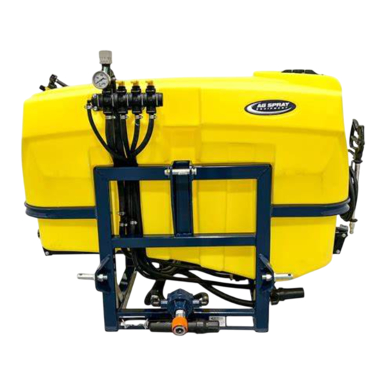
165 Gallon (5303646)
General Information
Thank You and Congratulations on purchasing your
new three point hitch sprayer. The purpose of this
manual is to assist you in operating and maintaining
your 3-Point sprayer.
WARNING:
Cancer and Reproductive Harm.
www.P65Warnings.ca.gov
Any Questions, Comments or Problems: Call your nearest AG SPRAY Location
BAKERSFIELD, CA
COLUMBUS, NE
877-724-2236
800-274-1025
MANKATO, MN
NEWTON, KS
507-388-6295
800-394-7662
OWNER'S MANUAL
Ag Spray MC2 Series 3 Point Sprayers
165 & 225 Gallon 3-Point Sprayers
and speak with one of our Friendly Technical Support Staff.
DOTHAN, AL
800-227-4098
PASCO, WA
800-634-2026
225 Gallon (5303647)
Please read it carefully, as it furnishes information
which will help you achieve years of trouble-free
operation. All units can be custom equipped to
meet all your spraying needs. The MC Series
3 Point is designed to fit Category II Lift Arms.
WARNING:
user must read and understand the operator's
manual before using this product.
FARGO, ND
HOPKINSVILLE, KY
701-280-2862
800-637-7172
TEMPE, AZ
877-974-7166
To reduce the risk of injury, the
[5195837
VISIT US ONLINE @
WWW.AGSPRAY.COM
(09/22)]
Page 1
Advertisement
Table of Contents

Subscribe to Our Youtube Channel
Related Manuals for AG SPRAY MC2 Series


Summary of Contents for AG SPRAY MC2 Series
- Page 1 Cancer and Reproductive Harm. user must read and understand the operator’s www.P65Warnings.ca.gov manual before using this product. Any Questions, Comments or Problems: Call your nearest AG SPRAY Location and speak with one of our Friendly Technical Support Staff. [5195837 (09/22)]...
-
Page 2: Table Of Contents
Table of Contents 3 - 6 Safety Information Hooking Up Sprayer Sprayer Boom Controls 8-13 Calibrating Sprayer Calibrating Sprayer: Boomless Nozzle Application Charts Calibrating Sprayer: Broadcast & Turf Application Chart 20” Spacing Operating Instructions Maintenance Instructions Winterizing Sprayer 16-40 Component Assembly Breakdowns MC2 165 Gallon 3 Point Assembly Breakdown - Base Unit MC2 225 Gallon 3 Point Assembly Breakdown - Base Unit 18-19... - Page 3 • Failure to keep body parts or clothing clear of the sprayer’s PTO drive shaft could result in serious injury or death. Ag Spray assumes no liability for any possible injury •...
- Page 4 Important Operation & Safety Information ----------------------------------- Before Operation -------------------------------------- • Carefully study and understand the owner’s manual • Read and follow chemical manufacturer’s labels, warnings and instructions! A material safety data sheet (MSDS) should be provided by the chemical manufacturer •...
- Page 5 Important Operation & Safety Information -------------------------------General Chemical Safety ---------------------------------- • READ and FOLLOW all chemical label’s instructions and warnings • AVOID inhaling, ingesting or coming into contact with any chemicals • KNOW applicable licensing and regulatory requirements for the chemical you plan to use •...
-
Page 6: Hooking Up Sprayer
Important Operation & Safety Information --------------------------------- Following Operation ------------------------------------ • Following operation, it is very important that you completely rinse the entire sprayer and all of it’s components of all chemical residue • Following operation, stop the tractor unit, set the brakes, disengage PTO shaft, shut off the engine and remove the ignition key •... -
Page 7: Sprayer Boom Controls
Sprayer Boom Controls Familiarize yourself with the sprayer controls before use. Your sprayer may be equipped with manual or electric (optional) boom controls. Pressure Relief/Regulating Valve If your sprayer is equipped with the manual lever controls: • Boom Section On/Off Valve--OFF when the lever is down or in the horizontal position, it is ON when the lever is up or in the Pressure Gauge vertical position. -
Page 8: Calibrating Sprayer
Calibrating the Sprayer When spraying with a boom, the sprayer must be calibrated to ensure proper spray coverage and to combat over-application or under application. Before calibrating the sprayer, it is important to familiarize yourself with the operating instructions. The calibration process is simplified when broken down into the following three steps: 1. - Page 9 Calibrating the Sprayer 2. Determine the nozzle size and use the calibration chart Always follow the chemical manufacturers label recommendations for application rate (GPA). There are five things you will need to know to be able to figure your nozzle size and pressure setting. They are: 1.
- Page 10 Calibrating the Sprayer 3. Adjusting the Sprayer Pressure Once you have found the correct pressure (psi) setting, you must now adjust the sprayer to that pressure setting. Before you adjust the sprayer’s pressure, it is important to follow these steps: 1.
- Page 11 Calibration Chart There are many different sizes and styles of spray tips available to meet your spraying needs. If you need further information, please contact an Ag Spray Service Center for assistance. Please Note: Flow rates are calculated using fresh water.
- Page 12 Calibrating the Sprayer BROADCAST & TURF APPLICATION CHART—20” SPACING Gallons per Acre GAL/1000 Sq. Ft. Flow 20-inch Nozzle Spacing 20-inch Nozzle Spacing Nozzle Pressure Rate Size (PSI) (GPM) 0.06 0.20 0.14 1.00 0.08 0.09 0.31 0.20 0.15 0.12 0.10 0.34 0.23 0.17 0.14...
- Page 13 Calibrating the Sprayer • 110° wide, tapered flat spray angle with air induction technology for better drift management • Made of 2-piece UHMWPE polymer construction which provides excellent chemical resistance, including acids, as well as exceptional wear life • Compact size to prevent tip damage •...
-
Page 14: Operating Instructions
Operating Instructions Before operating the sprayer, it is important that you read this entire manual and know all the safety precautions. Always take your time and be alert when operating your sprayer. This will allow you to safely spray without accident or interruption. Spraying with the Boom 1. -
Page 15: Maintenance Instructions
Contact an authorized Ag Spray Dealer for parts and technical support. Drain the Tank MC2 Series sprayers are equipped with a drain valve. The valve points towards the back of the sprayer. To drain, close the suction valve and open the drain valve. - Page 16 MC2 165 Gallon 3-PT Component Breakdown & Parts List MC2-165-3PT-BLU Control Assembly #5303646-BLU Detail Drain Valve Tank Drain w/Strainer Assembly Detail Suction Valve Not Shown: EPDM34 11 Ft. 3/4” - 200 PSI EPDM Spray Hose KF1300BLK 4 Ft. 1”-50 PSI Kanaflex Suction Hose Page 16...
- Page 17 MC2 225 Gallon 3-PT Component Breakdown & Parts List MC2-225-3PT-BLU Control Assembly #5303647-BLU Detail Drain Valve Suction Valve Tank Drain w/Strainer Assembly Detail Not Shown: EPDM34 11 Ft. 3/4” - 200 PSI EPDM Spray Hose KF1300BLK 4 Ft. 1”-50 PSI Kanaflex Suction Hose Page 17...
- Page 18 MX4 Series Boom Component Breakdown & Parts List Detail B Detail B See Next Page for Harness Detail MX408QJ (5303666) 8-Nozzle Boom Detail B Detail B See Next Page for Harness Detail MX410QJ (5303667) 10-Nozzle Boom Detail B Detail B See Detail C See Next Page for Harness Detail...
- Page 19 MX4 Series Boom Component Breakdown & Parts List MX408QJ (5303666) 8-Nozzle Boom Harness Opposite Side Has Typical MX410QJ (5303667) 10-Nozzle Boom Harness Hose and Nozzle Configuration MX412QJ (5303668) 12-Nozzle Boom Harness Page 19...
- Page 20 479 Boom Assembly Component Breakdown & Parts List Detail A Detail B Detail C Detail D See Detail A Detail E 479-6-8767 See Detail B See Detail D See Detail C Outer Boom Hinge 479-8 & 479-10 See Detail A 479-8-8767 See Detail B See Detail D...
- Page 21 479 Back Rack & Boom Stand Component Breakdown & Parts List Opposite Side has Typical Hardware Setup Page 21...
- Page 22 479 Boom Assembly Component Breakdown & Parts List Page 22...
- Page 23 479 Harness Assembly Component Breakdown & Parts List 479-6, 479-8, 479-10 QJD Center Nozzle Harness (#5277865) 479-6 QJD LH Nozzle Harness (#5277869) 479-6 QJD RH Nozzle Harness (#5277870) 479-8 QJD LH Nozzle Harness (#5277871) 479-8 QJD RH Nozzle Harness (#5277872) 479-10 QJD LH Nozzle Harness (#5277873) 479-10 QJD RH Nozzle Harness (#5277874) NOTES:...
- Page 24 2300 Boom Assembly Component Breakdown & Parts List Boom Retainer Detail LH & RH Boom Mount Brackets Page 24...
- Page 25 2300 Boom Assembly Component Breakdown & Parts List 5300325 Back Rack Assembly Detail C Detail B Detail A Detail A Detail B Detail C Page 25...
- Page 26 2300 Harness Assembly Component Breakdown & Parts List 2308-2310-2312 QJD Center Nozzle Harness (#5277767) 2308 QJD LH Nozzle Harness (#5277852) 2308 QJD RH Nozzle Harness (#5277853) 2310 QJD LH Nozzle Harness (#5277856) 2310 QJD RH Nozzle Harness (#5277857) 2312 QJD LH Nozzle Harness (#5277758) 2312 QJD RH Nozzle Harness (#5277759) NOTES: All hoses that are not...
- Page 27 BXT Series Boomless Boom Component Breakdown & Parts List 4058-BXT (5282451) Detail C Detail D RH Side Configuration Tee Nozzle Configuration LH Side Elbow Nozzle Configuration LH Side has typical configuration, as right hand side, however, bracket is the only part that is different.
- Page 28 PX4 - 80” Center Section Component Breakdown & Parts List Ref. # Part # Description Qty. Ref. # Part # Description Qty. 5281736 Assembly PX Boom 4-Nozzle Center Section 5006345 3/8-16 Flanged Top-Lock Hex Nut 5281746-CBK PX Boom 4-Nozzle Center Section 1.10 5034660 3/8-16 x 0.75 Flanged Hex Bolt...
- Page 29 PX4 Boom Single QuickJet Diaphragm (QJD) Component Breakdown & Parts List PX413-QJD PX416-QJD PX420-QJD PX423-QJD Ref. # Part # Description Qty. Qty. Qty. Qty. 5281736 Assembly PX Boom 4-Nozzle Center Section 5281732-CBK PX Boom Wing Weldment, 2-Nozzle 5281733-CBK PX Boom Wing Weldment, 3-Nozzle 5281731-CBK PX Boom Wing Weldment, 4-Nozzle 5281734-CBK PX Boom Wing Weldment, 5-Nozzle 5002489...
-
Page 30: Px4 Boom Power Fold Options
PX4 Boom Power Fold Options PX Boom Hydraulic Fold Option (Item # 5281777, 5281778, 5281779) Note: PX Boom Hydraulic Fold Kits are equipped with re- strictors in the elbow fittings threaded into the cylinders. Restrictors limit cylinder travel speed to prevent premature boom damage. - Page 31 Ref. # Part # Description Qty. PX Boom 12 Volt Electric Fold Option (Item # 5281774, 5281775, 5281776) 5281747-CBK PX Boom Cylinder Mount Weldment 5034481 1/4-20 0.75 Carriage Bolt 12V Connection Guideline: 5006344 1/4-20 Flanged Top-Lock Hex Nut Red = Positive (+) Black = Ground (-) 5031513 Sleeve Bearing, .625 ID x 0.877 OD x .625"...
- Page 32 Hamilton Boomless Assembly Component Breakdown & Parts List Hamilton #20 Boomless Kit MC1-20HAM-KIT (5282525) BXT Boomless Nozzle Component Breakdown & Parts List BXT Boomless Kit MC-24BXT-KIT (5282522) Page 32...
-
Page 33: Mc 3-Pt 22" Proseries Handgun Kit
Handgun Kits Component Breakdown & Parts List MC-PRO22-HG-KIT MC 3-PT 22” Pro Series Handgun #5282518 • No Drip Shut Off • Easy Pull Trigger Handle • Chemical Resistant Construction • 600 PSI, 8 GPM • 38’ Horizontal Throw & 27’ Vertical Throw To adjust the spray pattern, the nut needs to be adjusted (Ref. -
Page 34: Hose Reel Kit
Hose Reel Kit Component Breakdown & Parts List MC-M50HR22PS-KIT #5282547 Specifications 3/8" Hose Capacity 50 Ft. Swivel Pressure Rating 4000 PSI Inlet 3/8" NPT-F Outlet 3/8" NPT-F Max. Temp 225° F Features: Direct hand-crank rewind w/locking pin Solid steel construction Detail A: Thread the 3/8”... -
Page 35: Two Sec Valve Assembly
Valve Assembly Component Breakdown & Parts List MC Base 1 Section Control Two Sec Valve Assembly #5282495 Manual On/Off Section Valve Component Breakdown & Parts List Adder 1-Sec Valve Assembly w/1/2” HB #5282497 Handgun Valve Component Breakdown & Parts List Handgun 1-Sec Valve Assembly w/3/8”... - Page 36 RP-800 Series 8-Roller Pump Component Breakdown & Parts List RP-800C-B-PUMP-KIT #5282527 0 PSI 50 PSI 100 PSI 150 PSI 200 PSI 250 PSI 300PSI Imperial 540 RPM 0.80 0.38 0.68 0.97 1.29 1.65 1.91 1000 RPM 18.2 0.20 16.5 0.71 15.4 1.26 14.7...
- Page 37 7560XL Series 8-Roller Pump Component Breakdown & Parts List 7560XL-PUMPKIT 5276935 Pump 0 PSI 50 PSI 100 PSI 150 PSI 200 PSI 250 PSI 300PSI Speed 540 RPM 0.33 11.1 0.74 10.3 1.25 1.77 2.26 2.78 800 RPM 18.3 0.89 17.5 1.26 16.9...
- Page 38 MC-Electric Control Conversion Kits MC-1E-CONVRSN-KIT (5282543) MC-2E-CONVRSN-KIT (5282544) Conversion from Manual Controls to Electric Boom Section Control: 1. Remove the fork wire clip below the manual lever 2. Lift the manual lever out of the manifold 3. Insert the electric motor with electric connection facing forward making sure the align- ment grooves matchup and motor is down completely 4.
-
Page 39: Foam Marker Option
Foam Marker Option Components & Breakdown 14 5/32” 21 3/8” MC-FM6-KIT 5282550 901140 901627 901762 200005 800097 100044 100012 400366 901016 100029 200037 901162 100073 210506 901512=5mt. 901132 901513=7mt. 901503 901605 200039 901740 200044 800063 200043 200048 800064 100029 200043 100001 901011 800028... -
Page 40: Handwash Option
Handwash Option Components & Breakdown MC-HANDWASH-KIT 5282548 11 1/2” 21 1/4” 14 5/32” Page 40... -
Page 41: Warranty Info
WHAT REMEDIES ARE AVAILABLE UNDER THIS LIMITED WARRANTY. If the conditions set forth above are fulfilled and the Equipment or any part thereof is found to be defective, Ag Spray Equipment shall, at its own cost, and at its option, either repair or replace the defective Equipment or part. - Page 42 BAKERSFIELD, CA COLUMBUS, NE DOTHAN, AL FARGO, ND HOPKINSVILLE, KY 4618 SACO RD, 93308 5834 23rd ST, 68601 2401 FORRESTER RD, 36301 4350 48th AVE N, 58102 3303 PEMBROKE RD, 42240 661.391.9081 402.564.4544 334.673.0580 701.280.2862 270.886.0296 Toll Free: 877.724.2236 Toll Free: 800.274.1025 Toll Free: 800.227.4098 Toll Free: 800.373.4084 Toll Free: 800.637.7172...
Need help?
Do you have a question about the MC2 Series and is the answer not in the manual?
Questions and answers