Advertisement
Quick Links
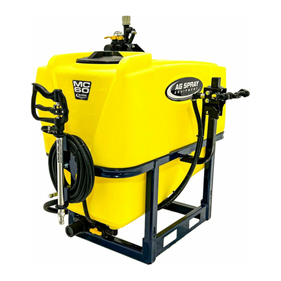
60 Gallon (5303641)
General Information
Thank You and Congratulations on purchasing your
new three point hitch sprayer. The purpose of this
manual is to assist you in operating and maintaining
your 3-Point sprayer.
WARNING:
Cancer and Reproductive Harm.
www.P65Warnings.ca.gov
Any Questions, Comments or Problems: Call your nearest AG SPRAY Location
BAKERSFIELD, CA
COLUMBUS, NE
877-724-2236
800-274-1025
MANKATO, MN
NEWTON, KS
507-388-6295
800-394-7662
OWNER'S MANUAL
Ag Spray MC1 Series 3 Point Sprayers
60 & 90 Gallon 3-Point Sprayers
and speak with one of our Friendly Technical Support Staff.
DOTHAN, AL
800-227-4098
PASCO, WA
800-634-2026
90 Gallon (5303642)
Please read it carefully, as it furnishes information
which will help you achieve years of trouble-free
operation. All units can be custom equipped to
meet all your spraying needs. The MC Series
3 Point is designed to fit Category I Lift Arms.
WARNING:
user must read and understand the operator's
manual before using this product.
FARGO, ND
HOPKINSVILLE, KY
701-280-2862
800-637-7172
TEMPE, AZ
877-974-7166
To reduce the risk of injury, the
[5195836
VISIT US ONLINE @
WWW.AGSPRAY.COM
(09/22)]
Page 1
Advertisement

Related Manuals for AG SPRAY MC1 Series


Summary of Contents for AG SPRAY MC1 Series
- Page 1 Cancer and Reproductive Harm. user must read and understand the operator’s www.P65Warnings.ca.gov manual before using this product. Any Questions, Comments or Problems: Call your nearest AG SPRAY Location and speak with one of our Friendly Technical Support Staff. [5195836 (09/22)]...
- Page 2 Table of Contents 3 - 6 Safety Information Hooking Up Sprayer Sprayer Boom Controls 8-13 Calibrating Sprayer Calibrating Sprayer: Boomless Nozzle Application Charts Calibrating Sprayer: Broadcast & Turf Application Chart 20” Spacing Operating Instructions Maintenance Instructions Winterizing Sprayer 16-30 Component Assembly Breakdowns MC1 60 Gallon 3 Point Assembly Breakdown - Base Unit MC1 60 Gallon 3 Point Assembly Breakdown - Base Unit FSBK-5 Boom Assembly...
- Page 3 • Failure to keep body parts or clothing clear of the sprayer’s PTO drive shaft could result in serious injury or death. Ag Spray assumes no liability for any possible injury •...
- Page 4 Important Operation & Safety Information ----------------------------------- Before Operation -------------------------------------- • Carefully study and understand the owner’s manual • Read and follow chemical manufacturer’s labels, warnings and instructions! A material safety data sheet (MSDS) should be provided by the chemical manufacturer •...
- Page 5 Important Operation & Safety Information -------------------------------General Chemical Safety ---------------------------------- • READ and FOLLOW all chemical label’s instructions and warnings • AVOID inhaling, ingesting or coming into contact with any chemicals • KNOW applicable licensing and regulatory requirements for the chemical you plan to use •...
-
Page 6: Hooking Up The Sprayer
Important Operation & Safety Information --------------------------------- Following Operation ------------------------------------ • Following operation, it is very important that you completely rinse the entire sprayer and all of it’s components of all chemical residue • Following operation, stop the tractor unit, set the brakes, disengage PTO shaft, shut off the engine and remove the ignition key •... - Page 7 Sprayer Boom Controls Familiarize yourself with the sprayer controls before use. Your sprayer may be equipped with manual or electric (optional) boom controls. Pressure Relief/Regulating Valve If your sprayer is equipped with the manual lever controls: • Boom Section On/Off Valve--OFF when the lever is down or in the horizontal position, it is ON when the lever is up or in the vertical Pressure Gauge position.
-
Page 8: Calibrating The Sprayer
Calibrating the Sprayer When spraying with a boom, the sprayer must be calibrated to ensure proper spray coverage and to combat over-application or under application. Before calibrating the sprayer, it is important to familiarize yourself with the operating instructions. The calibration process is simplified when broken down into the following three steps: 1. - Page 9 Calibrating the Sprayer 2. Determine the nozzle size and use the calibration chart Always follow the chemical manufacturers label recommendations for application rate (GPA). There are five things you will need to know to be able to figure your nozzle size and pressure setting. They are: 1.
- Page 10 Calibrating the Sprayer 3. Adjusting the Sprayer Pressure Once you have found the correct pressure (psi) setting, you must now adjust the sprayer to that pressure setting. Before you adjust the sprayer’s pressure, it is important to follow these steps: 1.
- Page 11 Calibration Chart There are many different sizes and styles of spray tips available to meet your spraying needs. If you need further information, please contact an Ag Spray Service Center for assistance. Please Note: Flow rates are calculated using fresh water.
- Page 12 Calibrating the Sprayer BROADCAST & TURF APPLICATION CHART—20” SPACING Gallons per Acre GAL/1000 Sq. Ft. Flow 20-inch Nozzle Spacing 20-inch Nozzle Spacing Nozzle Pressure Rate Size (PSI) (GPM) 0.06 0.20 0.14 1.00 0.08 0.09 0.31 0.20 0.15 0.12 0.10 0.34 0.23 0.17 0.14...
- Page 13 Calibrating the Sprayer KLC FieldJet Nozzles used on FSBK-1 Boom Assembly The KLC FieldJet nozzle is typically used to spray areas not accessible with a boom sprayer. It’s one-piece nozzle design projects spray to both sides to form a wide swath flat spray. The round orifice minimizes clogging. Uniformity across the swath is not as good as with a properly operated boom sprayer.
- Page 14 Operating Instructions Before operating the sprayer, it is important that you read this entire manual and know all the safety precautions. Always take your time and be alert when operating your sprayer. This will allow you to safely spray without accident or interruption. Spraying with the Boom 1.
-
Page 15: Maintenance Instructions
1. It is recommended to perform a visual and physical inspection for any worn parts, loose bolts or other visible problems. Make all necessary repairs before spraying. Please contact an authorized Ag Spray dealer to order parts or to receive technical help. - Page 16 MC1 60 Gallon 3-PT Component Breakdown & Parts List Control Assembly Detail Tank Drain w/Strainer Assembly Detail Not Shown: EPDM12 5 Ft. 1/2” - 200 PSI EPDM Spray Hose HC08 Qty.: 2 1/2” Hose Clamp EPDM34 5 Ft. 3/4” - 200 PSI EPDM Spray Hose HC12 Qty.: 2 3/4”...
- Page 17 MC1 90 Gallon 3-PT Component Breakdown & Parts List Control Assembly Detail Tank Drain w/Strainer Assembly Detail Not Shown: EPDM12 5 Ft. 1/2” - 200 PSI EPDM Spray Hose HC08 Qty.: 2 1/2” Hose Clamp EPDM34 5 Ft. 3/4” - 200 PSI EPDM Spray Hose HC12 Qty.: 2 3/4”...
- Page 18 FSBK-5 (5300976) Component Breakdown & Parts List Opposite side has typical hardware setup See Hinge Detail Clamp (Bag of 5) 5277729 Hinge Detail CROSS Page 18...
- Page 19 FSBK-70 (5301100) Component Breakdown & Parts List Opposite side has typical hardware setup See Hinge Detail Hinge Detail Clamp Bag of 7: 5277730 Elbow Cross Page 19...
- Page 20 MX4 Series Boom Component Breakdown & Parts List Detail B Detail B See Next Page for Harness Detail MX408QJ (5303666) 8-Nozzle Boom Detail B Detail B See Next Page for Harness Detail MX410QJ (5303666) 10-Nozzle Boom Detail B Detail B See Next Page for Harness Detail MX412QJ (5303666) 12-Nozzle Boom...
- Page 21 MX4 Series Boom Component Breakdown & Parts List MX408QJ (5303666) 8-Nozzle Boom Harness Opposite Side Has Typical MX410QJ (5303666) 10-Nozzle Boom Harness Hose and Nozzle Configuration MX412QJ (5303666) 12-Nozzle Boom Harness Page 21...
- Page 22 FSBK-3025BL (5301289) Component Breakdown & Parts List Center Nozzle Assembly End Nozzle Assembly See Next Page for proper assembly of End nozzles on the tube 36 Ft. Check the spray pattern. Usually you can see the coverage better on a solid concrete surface, such as a driveway. ...
- Page 23 FSBK-3025BL (5301289) End Nozzle Assembly & Info End Nozzle Assembly Procedure For Boomless “Wet” Boom The boom will come with the (2) end nozzle assemblies NOT affixed to your boom tube. Follow the instructions below to attach these properly to the boom tube, as shown. Assembled End Nozzle 1.
- Page 24 BXT Series Boomless Boom Component Breakdown & Parts List Model: 3438-BXT (5282450) (Boomless 34’ Coverage, 3.8 GPM @ 40 PSI) Detail A LH Side Configuration Detail B Elbow Nozzle Assembly Tee Nozzle RH Side Assembly RH Side has typical configuration, as left hand side, however, bracket is the only part that is different.
- Page 25 Hamilton Boomless Assembly Component Breakdown & Parts List Hamilton #10 Boomless Kit MC1-10HAM-KIT (5282538) BXT Boomless Nozzle Component Breakdown & Parts List BXT Boomless Kit MC-24BXT-KIT (5282522) Page 25...
- Page 26 Handgun Kits Component Breakdown & Parts List MC-PRO22-HG-KIT MC 3-PT 22” Pro Series Handgun #5282518 • No Drip Shut Off • Easy Pull Trigger Handle • Chemical Resistant Construction • 600 PSI, 8 GPM • 38’ Horizontal Throw & 27’ Vertical Throw To adjust the spray pattern, the nut needs to be adjusted (Ref.
- Page 27 Valve Assembly Component Breakdown & Parts List ARAG NPT+1 Two Sec Valve Assembly #5282495 Manual On/Off Section Valve Component Breakdown & Parts List ARAG 1-Sec Valve Assembly w/1/2” HB #5282497 Handgun Valve Component Breakdown & Parts List ARAG 1-Sec Valve Assembly w/3/8” HB #5282496 Page 27...
- Page 28 RP-600 Series 6-Roller Pump Component Breakdown & Parts List RP-600C-B-PUMP-KIT #5282526 0 PSI 50 PSI 100 PSI 150 PSI 200 PSI 250 PSI 300PSI Imperial 540 RPM 0.80 0.38 0.68 0.97 1.29 1.65 1.91 1000 RPM 18.2 0.20 16.5 0.71 15.4 1.26 14.7...
- Page 29 6500XL Series 6-Roller Pump Component Breakdown & Parts List 6500XL-PUMPKIT 5276977 0 PSI 50 PSI 100 PSI 150 PSI 200 PSI 250 PSI 300PSI Imperial 540 RPM 1000 RPM 18.2 16.5 15.4 14.7 14.0 13.4 12.7 1200 RPM 21.8 20.1 19.1 18.2 17.3...
- Page 30 MC-Electric Control Conversion Kits MC-1E-CONVRSN-KIT (5282543) MC-2E-CONVRSN-KIT (5282544) MC-3E-CONVRSN-KIT (5282545) Conversion from Manual Controls to Electric Boom Section Control: 1. Remove the fork wire clip below the manual lever 2. Lift the manual lever out of the manifold 3. Insert the electric motor with electric connection facing forward making sure the align- ment grooves matchup and motor is down completely 4.
-
Page 31: Warranty Info
WHAT REMEDIES ARE AVAILABLE UNDER THIS LIMITED WARRANTY. If the conditions set forth above are fulfilled and the Equipment or any part thereof is found to be defective, Ag Spray Equipment shall, at its own cost, and at its option, either repair or replace the defective Equipment or part. - Page 32 BAKERSFIELD, CA COLUMBUS, NE DOTHAN, AL FARGO, ND HOPKINSVILLE, KY 4618 SACO RD, 93308 5834 23rd ST, 68601 2401 FORRESTER RD, 36301 4350 48th AVE N, 58102 3303 PEMBROKE RD, 42240 661.391.9081 402.564.4544 334.673.0580 701.280.2862 270.886.0296 Toll Free: 877.724.2236 Toll Free: 800.274.1025 Toll Free: 800.227.4098 Toll Free: 800.373.4084 Toll Free: 800.637.7172...
Need help?
Do you have a question about the MC1 Series and is the answer not in the manual?
Questions and answers