Table of Contents
Advertisement
Quick Links
Advertisement
Table of Contents

Related Manuals for BREDABEDS URBAN STACK BUNK BED


Summary of Contents for BREDABEDS URBAN STACK BUNK BED
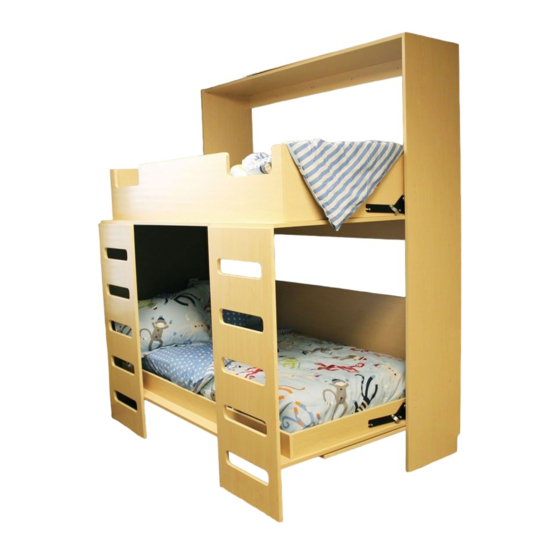
- Page 1 URBAN STACK BUNK BED Assembly Instructions Parts List Troubleshooting Tips Warranty REVISION: H|3.9 https://bredabeds.com Web: URB-SB 3318 West Nelis Drive Email: service@bredabeds.com OCTOBER 2022 1-855-466-4781 Meridian, ID 83646 Telephone:...
- Page 2 Thank you for purchasing a BredaBed! THANK YOU! Thank you for your Murphy Bed purchase by BredaBeds! When you’re ready to begin assembly, follow these instructions carefully and be sure not to skip any steps. If you have any trouble during the assembly process, feel free to contact us and one of our specialists will be happy to help guide you through the process.
-
Page 3: Table Of Contents
WARRANTY POLICY BredaBeds warranties all mechanical hardware for a period of ten (10) years, all wood parts on our products for a period of one (1) year to be free of material or workmanship defects and electronics (such as lights) for a period of ninety (90) days. Warranty periods begin from date of purchase. -
Page 4: Important Safety Information - Read This First
Never bypass safety checklists shown in this format without verifying each item in the checklist. If you have any questions, contact us (phone: 1-855-466-4781, email: service@bredabeds.com or live chat: https://bredabeds.com) before proceeding. Additionally - Keep children and pets away from work area during assembly for their safety. -
Page 5: Assembly Tips
Assembly Tips ASSEMBLY TIPS TWO PEOPLE ALLOW YOURSELF VIDEO RECOMMENDED SUFFICIENT TIME INSTRUCTIONS We recommend that When you’re ready Scan the QR Code above to view our two people assemble to begin assembly, Murphy Bed assembly our products. always give yourself video or visit: Throughout these suffi cient time so that... -
Page 6: Unpacking Your Bredabed & Frequently Asked Questions
I have damaged parts on my bed, what do I do? Do not begin assembly! As soon as you fi nd damage, send us an email at service@bredabeds.com with pictures of the damaged areas, part name(s) (found on the part label), provide your order number and any other additional information. -
Page 7: Troubleshooting
I have 3 or less stud locations to attach the Bed Cabinet to. Contact us to discuss attachment. Email us at service@bredabeds.com showing a photo of your Bed Cabinet with tape marking where your studs are located. -
Page 8: Parts List: Panels, Hardware Packages & Before You Begin
Parts List: Panels PARTS LIST: PANELS Bed Cabinet Panel List Bed Cabinet Left Side Bottom Bunk Left Rail Top Bunk Front Rail Bed Cabinet Right Side Bottom Bunk Right Rail Top Bunk Back Rail Stop Block (Qty 2) Bed Cabinet Top Top Bunk Left Rail Panel Substrate A (Qty 4) Bed Cabinet Top Nailer... - Page 9 Hardware Packages HARDWARE PACKAGES You will have 2 boxes of hardware, the following images are color-coded for each box: • Orange outline: Hardware can be found inside the small white or brown box. • Blue outline: Hardware can be found inside the box “Murphy Bed Mechanism”. Package #1 Card #2 Package #6...
- Page 10 Before You Begin Installation tools that are required Cordless Drill or Impact Driver #2 Phillips Screwdriver #2 and #3 Phillips bit Stud Finder Drill Bit Set Socket Set Level 1/2” Wrench or Adjustable wrench Tape Measure Ladder or Step Stool Rubber Mallet Gloves (Optional) UNDERSTANDING CAM FITTINGS...
-
Page 11: Chapter 1: Hardware Insertion
Chapter 1: Hardware insertion. Chapter 1: Hardware insertion. REQUIRED TOOLS REQUIRED HARDWARE • Hardware Package #1 • Rubber Mallet • Hardware Card #2 • Cordless Drill with #2 Phillips • Hardware Package #6 • 1/2” Socket • Allen Wrench (Hardware Card #2) Referring to Fig. - Page 12 Chapter 1: Hardware insertion. Referring to Fig. 1C, lay parts on floor and insert cam screws from Hardware Package #1 in holes marked with a circle STEP 3 using a cordless drill. Insert cam fittings from Hardware green Package #6 in holes marked with a circle using a rubber mallet.
- Page 13 Chapter 1: Hardware insertion. Referring to Fig. 1D, lay parts on floor and insert cam screws from Hardware Package #1 in holes marked with a circle STEP 4 using a cordless drill and insert cam fittings from Hardware green Package #6 in holes marked with a circle using a rubber mallet.
-
Page 14: Chapter 2: Bed Cabinet Assembly
Chapter 2: Bed Cabinet assembly. Chapter 2: Bed Cabinet assembly. REQUIRED TOOLS: #2 Phillips Screwdriver You’ll now assemble the Bed Cabinet on the floor directly in front of the wall where the OVERVIEW: bed will attach, then tilt the unit up. To do this, you’ll need at least 3 extra inches of height clearance. - Page 15 Chapter 2: Bed Cabinet assembly. FIG. 2C STEP 3 Slide “Bed Cabinet Left Side” in direction of arrow and tighten all cam fittings. FIG. 2D STEP 4 Attach “Headboard” and both “Bottom Nailers” as shown and tighten cam fittings. The Headboard will normally sit at a slight angle.
- Page 16 Cam fittings on the Bed Cabinet Top should face down and WILL be • visible from below. If any of these parts are backwards, they must be flipped around. If you have any question, contact us (phone: 1-855-466-4781, email: service@bredabeds.com or live chat: https://bredabeds.com) before proceeding.
-
Page 17: Chapter 3: Attaching The Bed Cabinet To The Wall
Chapter 3: Attaching the Bed Cabinet to the wall. Chapter 3: Attaching the Bed Cabinet to the wall. REQUIRED TOOLS REQUIRED HARDWARE • Cordless Drill and/or Impact Driver • Hardware Package #10 (white box) • #2 & #3 Phillips Bit •... - Page 18 Chapter 3: Attaching the Bed Cabinet to the wall. FIG. 3A - DRYWALL CUTAWAY SHOWING WALL STUDS STEP 2 Using a stud finder, locate and mark the exact center of each stud (see page 7 if you have 3 or less stud locations) along the “Bed Cabinet Top...
- Page 19 ***IN SERIOUS INJURY OR DEATH!*** DO NOT attempt to proceed if the Bed Cabinet Top Nailer is damaged or cracked. Contact BredaBeds for a replacement. DO NOT remove the warning tape on the Top Nailer. If the warning is missing or damaged, contact BredaBeds to receive replacement tape.
-
Page 20: Chapter 4: Installing Top/Bottom Bunks
Chapter 4: Installing Top/Bottom Bunks. Chapter 4: Installing Top/Bottom Bunks. REQUIRED TOOLS REQUIRED HARDWARE • #2 Phillips Screwdriver • Hardware Card #2 • 1/2” Socket & Wrench • Hardware Packages #17, #27 & #29 For video instructions of this step, visit: https://breda.us/springs DO NOT CLIMB OR PUT ANY WEIGHT ON EITHER BUNKS UNTIL LADDERS HAVE BEEN INSTALLED DURING CHAPTER 5 STEP 1! - Page 21 Chapter 4: Installing Top/Bottom Bunks. FIG. 4E STEP 2 Begin by laying out the rail parts for the Top Bunk in front of the Bed Cabinet wall unit. Parts are named with the orientation as viewed from the front. Tighten all connecting cam fittings.
- Page 22 Chapter 4: Installing Top/Bottom Bunks. FIG. 4G STEP 4 Lay the top door on a soft surface (blanket, carpet, rug, etc.) with the cam screws face up, then lay the bunk unit onto the door. Tighten all connecting cam fittings. The holes are offset closer to the back edge/...
- Page 23 Is the work area clear of children & pets? If you have any question, contact us (phone: 1-855-466-4781, email: service@bredabeds.com or live chat: https://bredabeds.com) before proceeding. For video instructions of these steps, visit: https://breda.us/face Slide the steel tube FIG.
- Page 24 Chapter 4: Installing Top/Bottom Bunks. The bolts for Holes A and B will attach from the inside of the panel/frame. In other words, the bolt heads will be on the inside of the panel/frame and the nuts will go on the outside of the panel/frame. Referring to Fig.
- Page 25 Chapter 4: Installing Top/Bottom Bunks. FIG. 4M STEP 9 Repeat 2-5 in this chapter to make the Bottom Bunk and review the safety checklist. Substrate A & B pieces should face down and tighten from the bottom. The holes are also offset closer to the back edge/ back rail.
-
Page 26: Chapter 5: Final Assembly And Adjustment
Chapter 5: Final assembly and adjustments. Chapter 5: Final assembly and adjustments. REQUIRED TOOLS REQUIRED HARDWARE • Cordless Drill • Hardware Card #2 • Hardware Package #28 • Mattress Strap • With 2 people and the Bottom Bunk in the closed position, STEP 1 open the Top Bunk 90 degrees. - Page 27 Chapter 5: Final assembly and adjustments. Check that the bunk doors have equal clearance top to bottom on the left and right sides. If the Bed Cabinet is STEP 3 leaning to one side, nudge it at the floor level. •...
-
Page 28: Chapter 8: How To Disassemble The Bed For Moving
Chapter 6: How to disassemble the bed for moving. Chapter 6: How to disassemble the bed for moving. REQUIRED TOOLS ESTIMATED TIME • Cordless Drill with #2 Phillips 30 Minutes • 1/2 Wrench or Adjustable Pliers Note: This is an average time only, yours may vary.
Need help?
Do you have a question about the URBAN STACK BUNK BED and is the answer not in the manual?
Questions and answers