
Related Manuals for FuzzDog AlluringEcho


Summary of Contents for FuzzDog AlluringEcho
- Page 1 Alluring Echo Splendid modulated tape-style delay Contents of this document are ©2022 Pedal Parts Ltd. No reproduction permitted without the express written permission of Pedal Parts Ltd. All rights reserved.
-
Page 2: Important Notes
Important notes If you’re using any of our footswitch daughterboards, DOWNLOAD THE DAUGHTERBOARD DOCUMENT • Download and read the appropriate build document for the daughterboard as well as this one BEFORE you start. • DO NOT solder the supplied Current Limiting Resistor (CLR) to the main circuit board even if there is a place for it. - Page 3 Schematic + BOM 100K 100K Jumper* PT2399 100n OPA2134 120K LM358 220K Empty* 78L05 120K D1-2 1N4148 220K 1N5817 100K 10u elec 4u7 elec 100KB 100n 100n GAIN 100KB/TRIM 330n 47u elec 100KB 100u elec 100KA 100n 47u elec 50KB 100K 100n 100u elec...
- Page 5 The power and signal pads on the PCB There are extra pads for the Gain trimmer so conform to the FuzzDog Direct Connection you can use different types. As long as there’s format, so can be paired with the appropriate a leg in each column marked above you’re OK.
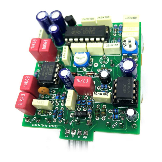
- Page 6 R31 Hack Oops. It’ll be fixed on V1.1 of the PCB, but for now this needs to be hacked in. It’s simple. Leave some of the leg of R19 above the board when mounting. When everything else is assembled simple place R31 from the exposed leg of R19 to pin 1 of the SPD pot, above D3. Adjusting the trimmers GAIN - turn all the controls down to zero.
- Page 7 Test the board! Check the relevant daughterboard document for more info before you undertake this stage. UNDER NO CIRCUMSTANCES will troubleshooting help be offered if you have skipped this stage. No exceptions. Once you’ve finished the circuit it makes sense to test is before starting on the switch and LED wiring.
- Page 8 Wire it up (if using a daughterboard please refer to the relevant document) BOARD BOARD INPUT BOARD BOARD BOARD BOARD BOARD BOARD BATTERY Wiring shown above will disconnect the battery when you remove the jack plug from the input, and also when a DC plug is inserted. The Board GND connections don’t all have to directly attach to the board.
-
Page 9: Drilling Template
35 5mm 27mm This template is a rough guide only. You should ensure correct marking of your enclosure before drilling. You use this template at your own risk. Pedal Parts Ltd can accept no responsibility for incorrect drilling of enclosures. FuzzDog.co.uk...
Need help?
Do you have a question about the AlluringEcho and is the answer not in the manual?
Questions and answers