Table of Contents
Advertisement
Quick Links
1470 Don Street • Naples, Florida 34104
Descriptions
007 Control Installation Instructions:
®
www.energenics.com
Installation & Operation Manual
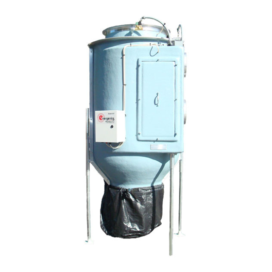
For ENERGENICS 007 Control
In-Line Space Saver Lint Filters
1
Telephone:
Fax:
Customer Service:
9002.5
9002.6
(239) 643-1711
(239) 643-6081
(800) 944-1711
Page
1
2
3
4
5
6
7
8
9
10
11
12
13
14
15
16
Advertisement
Table of Contents

Related Manuals for Energenics 007


Summary of Contents for Energenics 007
-
Page 1: Table Of Contents
1470 Don Street • Naples, Florida 34104 Telephone: (239) 643-1711 Fax: (239) 643-6081 Customer Service: (800) 944-1711 Installation & Operation Manual For ENERGENICS 007 Control In-Line Space Saver Lint Filters Descriptions Page Table of Contents Description of Lint Filter Operation Receiving and Installation Important Installation Considerations... -
Page 2: Description Of Lint Filter Operation
DESCRIPTION OF LINT FILTER OPERATION Your new Energenics Lint Filter operated with a UL approved control represents the most advanced features available in the laundry industry to date. The following list the functions and mode of operation: Blowdown (cleaning) – The Lint Filter will monitor the system backpressure and automatically initiate the blowdown cycle. -
Page 3: Receiving And Installation
Receiving and Installation Before you sign the Bill of Lading 1. Receiving- Inspect units inside and out for signs of damage Verify all components are delivered per the Bill of Materials. Report damage to the carrier IMMEDIATELY. Note ALL damage on the Bill of Lading. This is your responsibility and you must file all claims The filter is fully assembled and ready for installation. -
Page 4: Important Installation Considerations
Important Installation Considerations All Energenics Lint Collectors can be mounted indoors or outdoors. If it is mounted outdoors we recommend our Side Discharge or a field installed swept radius elbow (Gooseneck). Do not use a conical cap on the filter exhaust discharge. -
Page 5: Warnings/Cautions
If the filter is in position, make all final connections. Step 2. Mount the 007 control in a visible location on a solid vibration free surface and connect all components. Step 3. Provide dedicated electrical service to the transformer and test all systems. -
Page 16: Maintenance Requirements
Maintenance Requirements The frequency of your maintenance requirements depends upon the number of hours of operation and upon variances in your product output. For a single-shift operation, without special problems, the frequency recommended below should suffice. You should set your own schedule based on your experience. 1.
Need help?
Do you have a question about the 007 and is the answer not in the manual?
Questions and answers