Table of Contents
Advertisement
Quick Links
© Copyright 2012
EVERTZ MICROSYSTEMS LTD.
5292 John Lucas Drive,
Burlington, Ontario,
Canada,
L7L 5Z9
Phone:
Sales Fax:
Tech Support Phone:
Tech Support Fax:
Version 1.0, June 2012
The material contained in this manual consists of information that is the property of Evertz Microsystems and is intended solely for
the use of purchasers of the 3025SW Mini-Master Control Switcher. Evertz Microsystems expressly prohibits the use of this
manual for any purpose other than the operation of the master control switcher.
All rights reserved. No part of this publication may be reproduced without the express written permission of Evertz Microsystems
Ltd. Copies of this guide can be ordered from your Evertz products dealer or from Evertz Microsystems.
Master Control Switching
& Channel Branding
System Manual
+1 905-335-3700
+1 905-335-3573
+1 905-335-7570
+1 905-335-7571
3025SW
Internet:
Sales:
Tech Support: service@evertz.com
Web Page:
sales@evertz.com
http://www.evertz.com
Advertisement
Table of Contents

Subscribe to Our Youtube Channel
Related Manuals for evertz 3025SW


Summary of Contents for evertz 3025SW
- Page 1 Version 1.0, June 2012 The material contained in this manual consists of information that is the property of Evertz Microsystems and is intended solely for the use of purchasers of the 3025SW Mini-Master Control Switcher. Evertz Microsystems expressly prohibits the use of this manual for any purpose other than the operation of the master control switcher.
- Page 2 This page left intentionally blank...
- Page 3 IMPORTANT SAFETY INSTRUCTIONS The lightning flash with arrowhead symbol within an equilateral triangle is intended to alert the user to the presence of un-insulated “Dangerous voltage” within the product’s enclosure that may be of sufficient magnitude to constitute a risk of electric shock to persons. The exclamation point within an equilateral triangle is intended to alert the user to the presence of important operating and maintenance (Servicing) instructions in the literature accompanying the product.
- Page 4 WARNING Changes or Modifications not expressly approved by Evertz Microsystems Ltd. could void the user’s authority to operate the equipment. Use of unshielded plugs or cables may cause radiation interference. Properly shielded interface...
- Page 5 June 2012 Information contained in this manual is believed to be accurate and reliable. However, Evertz assumes no responsibility for the use thereof or for the rights of third parties, which may be effected in any way by the use thereof. Any representations in this document concerning performance of Evertz products are for informational use only and are not warranties of future performance, either expressed or implied.
- Page 6 3025SW Master Control Switching & Channel Branding This page left intentionally blank Revision 1.0...
-
Page 7: Table Of Contents
3025SW Master Control Switching & Channel Branding TABLE OF CONTENTS OVERVIEW ..........................1 1.1. FEATURES & BENEFITS ......................1 1.2. 3025SW SYSTEM OVERVIEW....................3 1.3. THE 3025SW PLATFORM....................... 3 INSTALLATION ........................5 2.1. UNPACKING ..........................5 2.2. INSTALLING AND REMOVING THE MODULES ..............5 2.2.1. - Page 8 3025SW Master Control Switching & Channel Branding 4.3. GENERAL CHANNEL INFORMATION ................. 37 4.3.1. Mini Master Mode ....................... 37 4.3.2. Channel Name and Description .................. 38 4.3.3. QMC-Link Address ..................... 39 4.3.4. Transition Timings ....................... 39 4.3.5. Default Transition ......................41 4.3.6.
- Page 9 3025SW Master Control Switching & Channel Branding 4.12.3 Video Diagnostic ......................75 4.12.4 Audio Diagnostic ......................75 4.12.5 System Log ......................... 75 4.12. SELECTIVE BYPASS ......................78 4.13. WIPES ............................ 79 4.13.1. Wipe Timing ........................ 79 4.13.2. View Table ........................80 4.13.3.
- Page 10 3025SW Master Control Switching & Channel Branding 6.3.1. QMC CP1000E – Key Definition ................113 6.3.2. QMC-CP1000E LCD Properties ................116 6.3.3. QMC-CP-E Key Definition..................117 6.3.4. QMC-CP-E LCD Properties ..................119 6.3.5. QMC-DCP – Dialog ....................120 6.3.6. QMC-DCP – Panel Properties .................. 124 6.3.7.
- Page 11 Figure 2-2: Connecting the Power to the Frame ..................10 Figure 2-3: Power Supply Status Indicators ....................11 Figure 2-4: 3025SW Rear Plate (left) and 3025EMC BNC Rear Plate (right) ..........13 Figure 2-5: VIDEO INPUT Connections..................... 14 Figure 2-6: VIDEO OUTPUT and MADI I/O Connections ................16 Figure 2-7: Breakout Panel ........................
- Page 12 3025SW Master Control Switching & Channel Branding Figure 4-9: Video Transition Offset 1 ......................43 Figure 4-10: Video Transition Offset -1 ...................... 43 Figure 4-11: Video Tab ..........................44 Figure 4-12: “Routed From” Drop Down Window ..................47 Figure 4-13: Configuring the Audio Monitoring Routing ................48 Figure 4-14: Audio Monitoring Location .....................
- Page 13 Table 4-4: 3025SW I/O No Keyers & No Emergency ................71 Table 4-5: 3025SW I/O Keyer 1 Only ......................72 Table 4-6: 3025SW I/O Keyer Keyers 1 & 2 Only ..................72 Table 4-7: 3025SW I/O Keyer 1, Keyer 2 & Emergency ................73 Table 4-8: GPI Functions ...........................
- Page 14 3025SW Master Control Switching & Channel Branding This page left intentionally blank Page viii Revision 1.0...
-
Page 15: Overview
Combined, these features create a reliable system for 24/7 year-round programming. The 3025SW offers a unique approach to SD/HD/3G master control with a number of options and a broad selection of configurable control panels. It can be assembled to meet any need and size. A 3025SW is comprised of an internal 14-input (maximum) router, full video and audio transition engine and advanced branding. - Page 16 Tiffs, TGA, Bitmaps, and WAV files) can be imported into the Evertz Overture™ media software and transferred to the 3025SW via Ethernet. Media is stored into flash memory that can be quickly recalled by the various control panels or automation.
-
Page 17: 3025Sw System Overview
1.3. THE 3025SW PLATFORM The 3025SW is designed to support 3 Gb/s, HD and SD video formats, including: 525i/59.94, 625i/50, 720p/59.94, 720p/50, 1080i/59.94, 1080i/50, 1080p/50, and 1080p/59.94 (SMPTE-425M-A & SMPTE- 425M-B). Each 3025SW processes a complete Program and Preset path each routed from one of the 14 (maximum) inputs to the internal router. -
Page 18: Figure 1-2: 3025Sw General Block Diagram
3025SW Master Control Switching & Channel Branding Figure 1-2: 3025SW General Block Diagram Page 4 Revision 1.0... -
Page 19: Installation
However, when modules and rear plates need re- positioning, or when additional modules are purchased, proper module/rear plate installation is required. Each 3025SW module is shipped with a matching rear panel plate that houses the appropriate connectors for that module. -
Page 20: Opening And Closing The Front Panel
2.3. MOUNTING The 3025SW frame is equipped with rack mounting rails and fits into a standard rack space. The 3000FR requires a 19” x 10.5” x 14.5” (483 mm x 260 mm x 368 mm) space, the EMX6-FR requires a 19”... -
Page 21: Cooling
2.4. COOLING The 3025SW frame is designed to ensure adequate cooling for up to 600 watts (3000FR and EMX6- FR) or 360 watts (EMX3-FR) of processing power per frame. Fans at the front and rear of each power supply module accomplish forced air-cooling. Adjacent equipment may be mounted immediately to the top and bottom of the frame. -
Page 22: Replacing The Power Supply
3025SW Master Control Switching & Channel Branding The fuse holder is located inside the power entry module. To change the fuses, disconnect the line cord from the power entry module and pull the fuse holder out from the power entry module using a small screwdriver. -
Page 23: Figure 2-1: Locating The Power Supply Mounting Screw
3025SW Master Control Switching & Channel Branding Install screw here Install screw here FUSE: 100-120V: T10AH250V 220-240V: T6.3AH250V THIS EQUIPMENT HAS MORE THAN ONE POWER SUPPLY CORD. TO REDUCE RISK OF ELECTRIC SHOCK GROUNDING OF THE CENTER PIN OF POWER SUPPLY CORD PLUGS MUST BE MAINTAINED. -
Page 24: Power
3025SW Master Control Switching & Channel Branding CAUTION: To reduce the risk of electric shock, you must replace the mounting screw after replacing the power supply. 2.6. POWER The power entry modules contain a standard IEC power inlet connector, two 5 x 20 mm fuse holders, and an EMI line filter. -
Page 25: Turning The Power On And Off
3025SW Master Control Switching & Channel Branding Power should be applied by connecting a three-wire, grounding-type power supply cord to the power entry module on the rear panel of each power supply. For use in North America, the power cord should be a minimum 18 AWG wire size;... -
Page 26: Frame Status Fault Conditions
3025SW MODULE REAR PANEL OVERVIEW Figure 2-4 shows the rear panel of the 3025SW unit. The BNC rear panel of a 3025EMC unit is also shown for reference Sections 2.9 to 2.11 describe the specific video, audio, and control signal. -
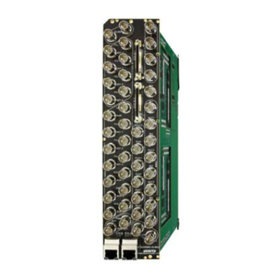
Page 27: Figure 2-4: 3025Sw Rear Plate (Left) And 3025Emc Bnc Rear Plate (Right)
CLN2 AUX 1 OUT3 AUX1 AUX 3 DVE 2 AUX2 DVE 1 OUT4 PGM OUT ETH B ETH A CLN OUT 3025EMC-IO-BNC MICROSYSTEMS LTD. Figure 2-4: 3025SW Rear Plate (left) and 3025EMC BNC Rear Plate (right) Page 13 Revision 1.0... -
Page 28: 3025Emc-Io-Bnc
3025SW Master Control Switching & Channel Branding Note: The 3025SW module REQUIRES 3 slots in any of the available frames. A slot blocker is installed on the module to prevent installation of other modular products. 2.8.1. 3025EMC-IO-BNC The 3025SW-IO-BNC uses BNC per IEC 61169-8 Annex A connectors for the video and audio connections. - Page 29 IN 2 (PST): Input 2 of the 3025SW Internal Router. IN 3 (KEY 1): Either Input 3 of the 3025SW Internal Router OR Keyer 1 Key Input (depends on EMC-Setup channel configuration). IN 4 (FILL 1): Either Input 4 of the 3025SW Internal Router OR Keyer 1 Fill Input (depends on EMC-Setup channel configuration).
-
Page 30: Figure 2-6: Video Output And Madi I/O Connections
3025SW Master Control Switching & Channel Branding 2.9.1.2. VIDEO OUTPUTS Figure 2-6: VIDEO OUTPUT and MADI I/O Connections PGM: Program Output with bypass protection. PGM 2: Program Output 2. This is a copy of Program Output. PRV: Preview Output. PRV 2: Preview Output 2. -
Page 31: Aes / Madi Inputs And Outputs
2.9.3.1. Audio Connections – Embedded (Serial Video) The 3025SW supports 16 channels of embedded audio from any of the 14 video inputs. The 3025SW also supports 16 channels of embedded audio from up to five inputs at any time which can be used as for voiceovers. -
Page 32: Figure 2-7: Breakout Panel
3025SW Master Control Switching & Channel Branding Figure 2-7: Breakout Panel 2.9.4.1. Serial I/O on the Breakout Panel The AUXIO-1 panel has four serial ports that can be used. The functions can be configured using EMC- Setup. The ports are divided into two ports that are RS-232 and two that are RS-422. Before the serial ports can be used they must be configured from the EMC-Setup program to have the controlling protocol and baud rates set correctly. -
Page 33: Table 2-3: Rs-422 Pin Outs
Table 2-5: AUX IO 2 GPI/O Logical Connector (optional) 2.9.4.3. CONNECTING THE GENERAL PURPOSE INPUTS AND OUTPUTS GPI interfacing with the 3025SW is possible through general-purpose inputs and outputs available on the 9000BHP-AUX breakout panels. The GPIs are active low with internal pull-up resistors (4.7k Ohms) to +5 V. -
Page 34: Figure 2-8: Gpi Input Circuitry
3025SW Master Control Switching & Channel Branding + 5 Volts 4.7 kΩ To Internal Circuit Figure 2-8: GPI Input Circuitry The GPOs are active low with internal pull-up (10kΩ) resistors to +5 V. When the output goes low, it is able to sink up to 10 mA;... -
Page 35: Connecting The Linear Time Code
CONNECTING THE LINEAR TIME CODE The 3025SW has a linear time code (LTC) input used to provide time information for the analogue or digital clock logos. Connect the LTC output from your house master time code source to the LTC IN XLR connector on the breakout panel. -
Page 36: Control Panel Installation: Qmc-Cp-1000E, Qmc-Cp-E & Qmc-Cp2048E
Category 5 cable must use Category 5 rated connectors. The maximum cable run between the 3025SW and the supporting hub is 300 ft (90 m). The maximum combined cable run between any two end points (i.e. 3025SW and PC/laptop via network hub) is 675 feet (205 m). -
Page 37: Electro Static Discharge (Esd) Precautions
3025SW Master Control Switching & Channel Branding See section 6.3.1 for more information on the operation of the CP-1000E Control Panel. Figure 2-10: QMC-CP-1000E Control Panel Figure 2-11: QMC-CP-E Control Panel Figure 2-12: QMC-CP-2048E Control Panel 2.13. ELECTRO STATIC DISCHARGE (ESD) PRECAUTIONS All semiconductor devices are sensitive to ESD. -
Page 38: Mounting
3025SW Master Control Switching & Channel Branding 2.14. MOUNTING The control panels are equipped with rack mounting rails and fit into a standard 19” 1RU or 2RU rack space. To securely fasten the frame to the equipment rack, make sure that all four mounting screws on each mounting rail are tightened securely. -
Page 39: Power
2.17.2. Connecting the Control Panels using Ethernet The control panels for 3025SW are designed for connection using 10Base-T (10 Mbps), 100Base-TX (100 Mbps) Ethernet cabling systems. There are two Ethernet ports labelled ETHERNET A and ETHERNET B, to provide for redundancy in the control system. As a result, either port may be used for connection to the 3025SW modules without compromise. -
Page 40: Control Panels Installation: Qmc-Dcp And Emc-Dcp
D9 serial cable to the DEBUG serial port and using a third party tool like Hyperterminal or TeraTerm with serial settings 115200, 8, None, 2, None. Please note that Qlink Mode can’t be used with the 3025SW. Only ETHERNET Mode can be used. ... -
Page 41: 3025Sw Configuration
This section describes the configuration of the 3025SW Switcher. In most applications the 3025SW will be controlled by an automation system and several industry standard third party systems are supported. A range of LCD button control panels can be added to the 3025SW, as a backup or simply for manual control. -
Page 42: Figure 3-2: 3025Emc Multi-Channel System
In a multi-channel system each 3025SW channel is independent of other channels. Each Automation driver has its own link to the 3025SW channel that it is controlling. In this way no single point of failure can stop transmission control of the majority of switcher channels. -
Page 43: Figure 3-3: Functional Block Diagram
3025SW Master Control Switching & Channel Branding Clean Output 1 AUX Output 1 Program Input Preset Input Program Output 1 2 channel DVE Emergency Input Program Output 2 Internal Video External External External Logo Key 1 Input Mixer Keyer 1... -
Page 44: Emc Configuration Software
The version number of the setup application software can be found by selecting “Help” then “About EMCSetup”. The opening screen is broken down into the three major pieces that are required for a 3025SW system. These sections are: •... -
Page 45: Setting Up Ip And Qlink
SETTING UP IP AND QLINK The 3025SW has two Ethernet ports compatible with a 10/100/1000 Base T networking running the TCP/IP protocol. The 3025SW will scroll the current Primary IP Address and Q-Link ID on the front display of the module. -
Page 46: Figure 4-2: Channel Selection For Ip Address Configuration
3025SW Master Control Switching & Channel Branding Next, choose Network then IP Address Setup. You will then be presented with the following dialogue. Figure 4-2: Channel Selection for IP Address Configuration Next, choose Default COM Port and the select OK. -
Page 47: Figure 4-4: Ascii Setup Window
3025SW Master Control Switching & Channel Branding Click Query Current to pull the current Port 1 configuration from the 3025SW. Then set the IP Address, Subnet Mask and Gateway to what are required (consult with Network Administrator if required). Then click Update. - Page 48 3025SW Master Control Switching & Channel Branding 5. Type .#98,N’ and the 3025SW will respond and show you the network settings that you have just configured. (SECONDARY IP) 6. Type “.#93,S192.168.10.100,255.255.255.0” or any appropriate settings for the second IP address and Netmask.
-
Page 49: Setting Up Qlink
Setting Up QLINK As mentioned in section 4.1, QLINK is a shared bus. If the 3025SW has multiple control panels, it needs a unique identifier called QLINK ID. This allows the 3025EMC to have a unique identifier on the shared configuration where multiple panels can connect to multiple channels. -
Page 50: Configuring A 3025Sw Channel
3025SW Master Control Switching & Channel Branding 4.2. CONFIGURING A 3025SW CHANNEL To start, double click on the Mixer Channels tab, and select NEW. The menu you will see is shown in Figure 4-5. For setting up a 3025EMC channel, select EMC3025 and click on OK button. -
Page 51: General Channel Information
Figure 4-6: Main Tab 4.3.1. Mini Master Mode IMPORTANT: Before proceeding any further with the configuration of your 3025SW channel, ensure that in the Options dialogue the Mini Master Mode checkbox is visible. If this is not visible, please follow the steps below: 1. -
Page 52: Channel Name And Description
3025SW Master Control Switching & Channel Branding 5. Navigate to the [General] section. This will near the bottom of the file. There will be a heading at the start of this section like this… ;///////////////////////////////// GENERAL ///////////////////////////////// [General] 6. Add this line under the [General] section heading but before the [Scheduler] heading…... -
Page 53: Qmc-Link Address
3025SWs to exist on a single bus. This configured value gives the 3025SW channel a unique ID (set in HEX notation) in a system with multiple channels. EMC-Setup will automatically start at 0x00 and increment by 1 for every channel added in the configuration. -
Page 54: Figure 4-7: Transition Adjustment Window
3025SW Master Control Switching & Channel Branding Figure 4-7: Transition Adjustment Window 4.3.4.2. Multiple Transition Adjustments The “Multiple Transition Adjustment” section enables you to adjust transition options at the same time. Speed Group: Enables you to select the speed of multiple transitions. Options include: Slow, Medium, Fast and Custom. -
Page 55: Default Transition
3025SW Master Control Switching & Channel Branding 4.3.5. Default Transition This is the transition type that will be first displayed on a control panel at power up. 4.3.6. Customizations Add a checkmark to this box to enable “Emergency used for Breakaway Audio” option. This feature is not currently supported. -
Page 56: Frame Delay
3025SW Master Control Switching & Channel Branding Auto-select Keyer Enable: With this option enabled the Keyer Transition Enable state will be enabled automatically when a Keyer is preset (level is enabled). Mini-Master Mode: This must be enabled when using the 3025 as an SW master control switcher. -
Page 57: Figure 4-9: Video Transition Offset 1
3025SW Master Control Switching & Channel Branding expected time with respect to the transition start and the video will start one field (interlaced frame/progressive frame) later. The duration of the video and audio transitions will not be affected, i.e. if the duration is 12 frames then the duration of both video and audio transition will be 12 frames. -
Page 58: Video Configuration
Video Standard This parameter enables you to select a desired video standard. This sets the video standard of the 3025SW channel. This section allows for the configuration of the reference signal type of “HD Tri-level Sync” or “Bi-level Sync” option. -
Page 59: Output
Entire vertical area of video is blanked. Selective Bypass: Selective lines of vertical area of video are forwarded untouched by the 3025SW. The lines are selected under the Selective Bypass tab. The remaining vertical area is blanked. Bypass: Entire vertical area of video is forwarded untouched by the 3025SW. -
Page 60: Dve
The section applies only if the +DVE-2D (2 channel DVE) option has been purchased for the 3025SW. This configures the 3025SW to recognize the DVE and place it with the video processing path of the EMC. Select the “Check Hardware” button to verify how many DVE channels available. Based on the ordering option the correct configuration options are made available to the user. -
Page 61: Using Aux For Audio Monitoring
Preset O/Ps. Note that currently the drop-down menus for the 3025SW configuration will show the inputs as Program Input, Preview Input etc. Table 4-3 shows how the drop-down menu settings apply to the 3025SW-IO-BNC rear plate. -
Page 62: Figure 4-13: Configuring The Audio Monitoring Routing
2. V/O 5 now becomes unavailable to be used as a normal voiceover. 3. The audio bars for the 3025SW channel that are available on the LCD (optional) of the EMC- DCP and QMC-DCP panels and on the software version of the QMC-DCP will change mode and show the audio metering for the Aux Bus and not the Clean Bus. -
Page 63: Figure 4-14: Audio Monitoring Location
3025SW Master Control Switching & Channel Branding AUDIO DE-EMBEDDER VIDEO INPUTS AUDIO AUDIO AUDIO AUDIO GAIN SHUFFLE MIXER SHUFFLER CONTROL SAMPLE RATE CONVERSION (SRC) DISCRETE AUDIO LOCATION LOCATION LOCATION INPUTS AUDIO MONITORING ROUTING Figure 4-14: Audio Monitoring Location Location 1 – Output of the Preshuffler Audio from the output of the pre-shuffler stage in the audio processing pipeline routes audio from directly after the pre-shuffler. -
Page 64: Input Timing Window Adjustment
4.4.7. Input Timing Window Adjustment The 3025SW requires video to be timed with respect to reference input with an accuracy of +/- ½ a video line. This ensures clean video and audio transitions. The Input Timing Window Adjustment enables you to set the horizontal position for the input timing window to account for an offset. Click the “Edit Timing”... -
Page 65: Audio Configuration
Figure 4-16: Audio Tab 4.5.1. Input Parameters These parameters will determine the state that the 3025SW will default to when the power is cycled or the 3025SW is reconfigured. Users will set the audio format for the various inputs of the 3025SW. - Page 66 Any of Key1, Fill1, Key2, Fill2, Key3, Fill3, Aux1, Aux2, Aux3, DVE1 and DVE2 can be assigned to the voiceover 1 de-embedder. See Table 4-3 on page 49 for details on how the input bus corresponds to the 3025SW-IO-BNC rear plate. AES MADI: Not Supported on the 3025SW.
-
Page 67: Metadata Router/Metadata Presets
4.5.3.1. Change Input Parameters on Source When the preset or program bus is changed from source to source the 3025SW can optionally change the audio gain and shuffling of the input bus to the configuration determined by that source. This option enables this function to be active, if the option is not checked then the audio parameters do not change when source selections are made to the preset or program bus. - Page 68 4.5.3.3. Save Audio Changes to Source The 3025SW user can optionally change the audio gain and shuffle on the program and preset bus, if this option is checked then this value is saved to the selected source, so that the next time this source is selected the same audio parameters are applied (if option 1 is selected).
-
Page 69: Audio Input Defaults/Stores
3025SW Master Control Switching & Channel Branding 4.6. AUDIO INPUT DEFAULTS/STORES These parameters will determine the state that the 3025SW will default to when the power is cycled or the 3025SW is reconfigured. Figure 4-17: Audio Input Defaults / Stores Tab Page 55 Revision 1.0... -
Page 70: Bus Defaults
This option is only available on the PGM Bus. This option is normally used when Dolby-E is required to “pass-through” the 3025SW’s audio mixer. Any channel pairs that are configured for Data/Dolby will not transition with the rest of the channels; they will simply cut to avoid corruption of the encoded data stream. -
Page 71: Transition Time
3025SW Master Control Switching & Channel Branding VO2: This is the ratio of VO2 audio that will be mixed when a voiceover (or combination of voiceovers) is applied. 100% means that 100% of VO2 audio will be mixed and 0% means that the VO2 audio component of the audio mix will be silent. -
Page 72: Foreground Ratio
Foreground Ratio This option has been removed from the configuration. 4.6.8. Stores The 3025SW offers ten Audio Input Stores which can be applied to any bus. Not all settings apply to all buses. 4.7. AUDIO SHUFFLER This tab allows users to configure the audio shuffler. This allows the audio input channels (A1, A2, etc) to be mapped to the audio output channels. - Page 73 3025SW Master Control Switching & Channel Branding Voiceover 1: If VO1 is configured to take AES inputs then the shuffler will be 4 inputs by 16 outputs. If VO1 is configured to take AES AP inputs then the shuffler will be 4 inputs by 16 outputs.
-
Page 74: Figure 4-19: Voiceover Duck & Mix
3025SW Master Control Switching & Channel Branding Figure 4-19: Voiceover Duck & Mix This allows the user to configure the mixing and ducking channels for each voiceover. For the previous example (Figure 4-19), VO1 has been configured so that when VO1 is applied channels A1 to A8 of the PGM/PST audio will be ducked (to the level specified in the PGM/PST ratio setting in the Audio Input Defaults/Stores configuration tab). -
Page 75: Shuffle Stores
3025SW Master Control Switching & Channel Branding Figure 4-20: VO4 Audio Clip Duck & Mix When Audio Clips are used the VO4 channels that are mixed and the PGM/PST channels that are ducked is determined automatically by the number of channels that are present in the audio wav file. -
Page 76: Figure 4-21: Shuffle Stores
3025SW Master Control Switching & Channel Branding Figure 4-21: Shuffle Stores In the above example, this store will apply this mapping to the bus that the shuffle store is applied to by the user. In the same way that the voiceovers have a mixing and ducking mapping, the shuffle stores also have voiceover mixing and ducking options. -
Page 77: Keyer
3025SW Master Control Switching & Channel Branding 4.8. KEYER Figure 4-22: Keying Levels Tab 4.8.1. Internal Keyer Routing / Priority Each physical keyer (keyer 1 - 2) can select which fill and key signal can be applied to its input. The... -
Page 78: Options
4.8.2. Options 4.8.2.1. On-Air by Default This option selects whether this keyer will be on-air if the 3025SW channel has a power cycle or re- configuration. Please note: The Internal Branding Keyer is always On-Air. Any media that is faded-in or cue’d will be visible without any keyer level or keyer on-air controls. -
Page 79: Key Signal Settings
3025SW Master Control Switching & Channel Branding 4.8.2.8. Auto Toggle This setting forces the M2100 control of the 3025SW to be toggled with the Emergency enable/disable. 4.8.2.9. Hold on Transition When checked, Emergency will stay on-air regardless of transitions. If disabled, Emergency will go off- air with the next transition. - Page 80 3025SW Master Control Switching & Channel Branding 4.8.3.4. Self Key This mode is used if there is no key signal associated with the fill signal. When this option is used the fill signal is applied internally to the key input. All other key setting options still apply.
-
Page 81: Global Option
PORTS This tab enables the user to edit the configuration of the Q-link and serial ports. Each 3025SW channel has a maximum of six serial ports (requires AUX I/O 2). Each of which can be set to handle any one of a number of protocols. -
Page 82: Protocol Settings
Serial 1 (DB1 on breakout panel): This port would typically be used for serial upstream router control. However, since the 3025SW does not use an upstream router this can be used for another purpose. Q-Link 1 (not used for 3025SW): This port does not exist on the 3025SW and must be set to “no protocol”. -
Page 83: Qlink Over Ethernet
(Options->Communications) of EMC-Setup. If set to “Serial”, then the serial port will be used to download configuration to the 3025SW channel. If set to “Network”, the IP address set in the IP Addr dialogue box will be used to upload configuration to the 3025SW channel. -
Page 84: Minimaster
4.10. MINIMASTER The 3025SW has been designed so that an upstream router is not required to feed the inputs. There are a maximum of 14 inputs that are available as sources for the PGM/PST buses but this changes depending on the configuration of the 3025SW channel. If the user requires the use of Keyer 1, Keyer 2 and Emergency then only 9 of the inputs on the 3025SW-IO-BNC will be available for use as sources for the PGM/PST buses. -
Page 85: Table 4-4: 3025Sw I/O No Keyers & No Emergency
3025SW Master Control Switching & Channel Branding INPUT: This is the physical input BNC on the 3025SW-IO-BNC rearplate. SOURCE: This is the actual number of the source when it is being recalled from automation (M2100), control panel (EMC-DCP etc) or by GPI. The INPUT fixed but the SOURCE will change depending on the configuration for the Keyers and Emergency. -
Page 86: Table 4-5: 3025Sw I/O Keyer 1 Only
4 (Unavailable used for Keyer 1 Fill) 5 (Unavailable, used for Keyer 2 Key) 6 (Unavailable, used for Keyer 2 Fill) SRC-3 SRC-4 SRC-5 SRC-6 SRC-7 SRC-8 SRC-9 SRC-10 TEST PATTERN SRC-11 Table 4-6: 3025SW I/O Keyer Keyers 1 & 2 Only Page 72 Revision 1.0... -
Page 87: As-Run/Diagnostics
Table 4-7: 3025SW I/O Keyer 1, Keyer 2 & Emergency Depending on the configuration between 9 and 14 physical inputs on the 3025SW can be available for the PGM/PST buses. Care must also be taken when configuring the EMC-Setup Source Table. Details on this configuration can be found later in the manual. -
Page 88: Logging General
3025SW Master Control Switching & Channel Branding Figure 4-25: As-Run/Diagnostics Tab 4.12.1 Logging General QMC Logging Port: Not required. This is handled by the Syslog feature. QMC Logging Level: Not required. This is handled by the Syslog feature. 4.12.2 Port Logging Levels This is not required and is handled by the Syslog feature. -
Page 89: Video Diagnostic
As this is commonly the case this tick box should normally be ticked. Disable Mute on Audio Error: The 3025SW looks for errors on its AES inputs and when an error is detected in either the left or right data then both the left and right (the entire AES stream) is normally muted. -
Page 90: Figure 4-26: Ftp Upload Of Syslog.conf File
The system logging IP address is only required if the syslog over IP is needed. The Serial logging, IP logging (enable/disable) and the logging level is configured using a syslog.conf file that is present in the “config” folder of the 3025SW’s CF card. A syslog.conf will be loaded to the CF prior to the 3025SW leaving the factory. - Page 91 “#com4.* syslog,console” Configure the 3025SW channel to log all logging levels for serial port 4 to both the serial console (console) and the syslog (IP). The serial logging (console) is logged to the 3025SW debug serial port (J11) which can be found on the front edge of the board.
-
Page 92: Selective Bypass
SELECTIVE BYPASS The 3025SW allows the lines in the vertical period to be either blanked or bypassed. The recommended setting for Vertical Blanking Selective Bypass is lines 6 & 7 (SD) or lines 7 & 8 (HD) to be blanked. For more information regarding the Vertical Blanking configuration see section 4.4.2. -
Page 93: Wipes
3025SW Master Control Switching & Channel Branding 4.13. WIPES Figure 4-28: Wipes Tab Preset: The 3025SW supports up to 5 pre-defined wipes. Each pre-defined preset has a legend name that will be used on the control panel. 4.13.1. Wipe Timing Speed: The user can specify 4 wipe speeds (Slow/Medium/Fast/Custom). -
Page 94: View Table
3025SW Master Control Switching & Channel Branding 4.13.2. View Table Selecting this button will open the “Transition Adjustment” window as illustrated in Figure 4-29. This window enables you to view your current transition details for each transition. Figure 4-29: Transition Adjustment Window 4.13.3. -
Page 95: Wipe Characteristics
3025SW Master Control Switching & Channel Branding New Value: Enables you to enter a new value to the designated preset. Click the “Update” button to update the transition details. Select the “Save” button to ensure your changes are saved. 4.13.4. -
Page 96: Time/Date
3025SW Master Control Switching & Channel Branding 4.14. TIME/DATE This tab enables the user to the set the time, date, and time zone. Figure 4-30: Time/Date Tab Source: Select a source using the drop down menu. Options include: Manual, Use this computer’s time &... -
Page 97: Gpi/O's
3025SW Master Control Switching & Channel Branding Date: This field sets the date. Time: This field sets the time. Time Zone: Select a time zone using the drop down menu. Server IP: This field sets the NTP Server IP address. The NTP server will be the source for the time related media and logging. -
Page 98: Gpi Control
3025SW Master Control Switching & Channel Branding 4.15.1. GPI Control GPI: This is the GPI number that function will be assigned to. GPIs 1 to 16 can be configured here. Type: A GPI can trigger a number of functions. The list of functions is described in Table 4-8. - Page 99 3025SW Master Control Switching & Channel Branding Function Description Parameter 1 Parameter 2 Not Used No function is defined. Transition Take Initiates a transition Selects the Background Level background level Keyer 1 Level Selects keyer 1 level Keyer 2 Level...
- Page 100 3025SW Master Control Switching & Channel Branding Selects voice-over 3 Voice Over Ratio Voice Over 3 Ratio ratio to be that defined 0 → 100 in parameter 1 Selects voice-over 4 Voice Over Ratio Voice Over 4 Ratio ratio to be that defined 0 →...
- Page 101 3025SW Master Control Switching & Channel Branding Selects a Fade-Cut Fade Cut Transition transition. Audio Follow Video Selects the audio Transition mode. Audio Only Selects the audio Transition mode. Audio Lag Selects the audio Transition mode. Audio Lead Selects the audio Transition mode.
-
Page 102: Gpi Scripts
GPI Scripts A maximum of 32 GPI related scripts can be loaded onto the 3025SW’s CF card (in the logos folder). There are 16 scripts that specify a media action for the gpi closed state (i.e. pin grounded) and 16 scripts that specify an action for the gpi open state (i.e. -
Page 103: Gpo Control
3025SW Master Control Switching & Channel Branding 4.15.3. GPO Control GPO: This is the GPO number that function will be assigned to. GPOs 1 to 16 are supported. Type: An EMC function can trigger a GPO. The list of functions is described in Table 4-9. - Page 104 3025SW Master Control Switching & Channel Branding Function Description Parameter 1 Parameter 2 Not Used No function is defined Active when in In Transition transition Active when Background Level background level is selected Active when keyer 1 Keyer 1 Level...
- Page 105 3025SW Master Control Switching & Channel Branding Active when voice- Voice Over Ratio Voice Over 2 Ratio over 2 ratio is same as 0→100 defined in parameter 1 Active when voice- Voice Over Ratio Voice Over 3 Ratio over 3 ratio is same as 0→100...
- Page 106 3025SW Master Control Switching & Channel Branding Audio Lead Active when this audio Transition mode is selected Active when in fade to Fade to Black black/silence Bypass QMC Active when in bypass Active with the source Source is ZERO defined by parameter Bus number.
-
Page 107: Gpo Scripts
4.15.4. GPO SCRIPTS There is only one GPO related script that can be loaded onto the 3025SW’s CF card (in the logos folder). Within this script the GPOs are configured to be active based on the state of named media. - Page 108 3025SW Master Control Switching & Channel Branding The GPO script can be created using a text editor (e.g. Notepad) and should have no file extension. The naming of the GPO script should be the following format: gpo_config_script Each GPO can only be configured to trigger (become active) based on any media being on-air or specific named media being on-air.
-
Page 109: Eas
This section configures the Emergency Alert System (+E) option. The +E option is only available in North America. A typical system would use an EAS device externally to the 3025SW. The EAS device will send the EAS alert text over a serial or IP interface based on the device. This tab configures the properties of the EAS crawl itself. -
Page 110: Figure 4-32: Eas Tab
EAS configuration dialogue will be displayed is the (+EAS) option was successfully found on the device. If the option is not found or if the software is unable to connect to the 3025SW to verify then the following will be displayed: Page 96 Revision 1.0... -
Page 111: Eas Vertical Position
The first thing that should be done when the 3025SW has connected to the channel is click “Update”. This uploads the list of true type font (TTF) files that are currently present in the 3025SW’s static storage. TTF files are required to render the EAS crawl text. Whenever the 3025SW configuration is reopened the EAS tab will prompt the user to update the font list by notifying the user of “Update Required”. -
Page 112: Eas Rate
3025SW Master Control Switching & Channel Branding 4.16.4. EAS Rate The EAS Rate option is used to set the speed with which the scrolling text moves from right to left across the screen measured in seconds. The default is 8 seconds. The parameter is adjusted in 1 second increments. -
Page 113: Temperature
This section configures the temperature parameters. This is the source used for temperature graphics that are used on the 3025SW. An optional air temperature probe is available (+TP) and can be used as a source for the temperature. Please refer to section 8.1 to set up the temperature probe. -
Page 114: Setting The Temperature Source
METAR is widely used in the aviation industry to obtain meteorological data from airports. The 3025SW can extract the temperature from the data and use it for media displaying temperature. The use of this feature requires a connection to the Internet. -
Page 115: Figure 4-35: Metar Tab
Temperature logos will be immediately updated each time the temperature is retrieved from the METAR server. Poll Interval at Failure: Enter how long you would like the 3025SW to wait before trying to retrieve the temperature from the METAR server after a failed attempt. -
Page 116: Proxy
(+TXT) or metar is being used the data source for these objects can be fed using RSS feeds and or metar. These feeds are typically on the outside of most corporate firewalls. These parameters allow the 3025SW to use the company’s proxy server to externally access the data. Figure 4-36: Proxy Tab 4.18.1. -
Page 117: Domain Name Server
3025SW Master Control Switching & Channel Branding Port: This field enables the user to select the port. This is the port to use on the company’s proxy server used to access external websites. This should be provided by the IT administrator. -
Page 118: Figure 4-37: User Transitions
3025SW Master Control Switching & Channel Branding Figure 4-37: User Transitions User Transition: Select a user transition (1 to 5) from the drop down menu and check the “Enabled” box in order to enable the transition. Transition Name: Provide a name for the transition using the text field. -
Page 119: Video & Keyer Timings
3025SW Master Control Switching & Channel Branding 4.19.1. Video & Keyer Timings Type: Enables you to select to the transition type. Types include: Cut, V Fade, Cut-Fade, Mix, and Fade-Cut. Duration: Enables you to set the total duration. Fall / Dwell / Rise: Enables you to the set the fall, dwell, and rise options. -
Page 120: Multiple Transition Adjustments
3025SW Master Control Switching & Channel Branding 4.19.3. Multiple Transition Adjustments The “Multiple Transition Adjustment” section enables you to adjust transition options at the same time. Speed Group: Enables you to select the speed of multiple transitions. Options include: Slow, Medium, Fast, or Custom. -
Page 121: Configuring Source Names And Router Size
3025SW Master Control Switching & Channel Branding CONFIGURING SOURCE NAMES AND ROUTER SIZE The 3025SW does not interface with an upstream router. This section describes how to configure the sources that are available to the 3025SW. In the main EMC-Setup window, select Sources and you will see the following window:... -
Page 122: Configuring Current Source
This drop-down combo box selects any audio shuffling stores configure in section 4.7 applied to the 3025SW when this source is selected to the preset or program bus. If no change is required when this source is selected set this to the first selection "Unchanged". -
Page 123: Keyer Parameters
Control: If the 3025SW is required to trigger the play command to the device the control method, either serial or GPO control can be defined. If the control method is GPO then the corresponding GPO must be configured for “Manual GPO”. If the control method is Machine Control then the corresponding serial port should be configured for Sony VTR Protocol. -
Page 124: Control Panels
The 3025SW system supports a range of manual control panels that can be used individually or in pairs. A system can consist of a single panel dedicated to a single 3025SW channel. Others can consist of a single (or multiple) control panels controlling multiple 3025SW and/or EMC channels. The 3025SW can be connected to various types of control panels (QMC-CP-E, QMC-CP-1000E, QMC-CP-2408E, QMC- DCP and EMC-DCP) to allow manual operation. -
Page 125: Qmc-Cp-2048E
QMC-CP-2048E is logically associated with the QMC-CP-1000E or QMC-CP-E to allow for users to expand controls. As with all the control panels for the 3025SW, the LCD buttons are fully configurable to suit the customer application. The LCD buttons also offer different colours to show status. -
Page 126: Multi Channel Panels
5 shaft encoders and 15 additional LCD buttons. As with all the control panels for the 3025SW, all the buttons on the QMC-DCP are fully configurable to suit the customer application. The LCD buttons also offer different colours to show status 6.2. -
Page 127: Qmc Cp1000E - Key Definition
The available panel types are listed when you pull down the menu. For the 3025SW, the only panel types that are supported are: QMC-DCP (EMC-DCP), QMC- CP1000E, QMC-CP2000E, and QMC-CP2048E. The others are invalid panel types that will not work with the 3025SW or EMC. -
Page 128: Figure 6-6: Qmc-Cp-1000E Key Definition Tab
QLink Address (in Hex): This is the Q-Link Address of the panel. Similar to QLink addressing for the EMC to communicate with an Evertz router, the panels use the same scheme to interact with the 3025SW channels. This Q-Link address has to match the Q-Link set on the control panel itself. - Page 129 This is the channel the panel will control when it powers up. Automation Mode: This is the operational mode that the panel will be in when the 3025SW is in automation mode. The panel can be either: Panel enabled, Panel disabled, or Limited functions.
-
Page 130: Qmc-Cp1000E Lcd Properties
This will change the colour of the currently selected key type, when changing the selection the colour setting shown in the greyed-out edit box will change to show the result of the change. Restore: This will restore all the key type colours to the Evertz standard. Page 116 Revision 1.0... -
Page 131: Qmc-Cp-E Key Definition
This is the QLink Address of the panel. Similar to Q-Link addressing for the EMC to communicate with an Evertz router, the panels use the same scheme to interact with the 3025SW channels. This Q-Link address has to match the Q-Link set on the control panel itself. - Page 132 This is the channel the panel will control when it powers up. Automation Mode: This is the operational mode that the panel will be in when the 3025SW is in automation mode. The panel can be either: Panel enabled, Panel disabled or Limited functions.
-
Page 133: Qmc-Cp-E Lcd Properties
Restore: This will restore all the key type colours to the Evertz standard. Save Default: This will save the current colour settings as the default for any LCD panels that are created subsequently. -
Page 134: Qmc-Dcp - Dialog
This is the QLink Address of the panel. Similar to QLink addressing for the EMC to communicate with an Evertz router, the panels use the same scheme to interact with the 3025SW channels. This QLink address has to match the QLink set on the control panel itself. - Page 135 Channel: This is the channel the panel will control when it powers up. Automation Mode: This is the operational mode that the panel will be in when the 3025SW is in automation mode. See section 6.3.1.2. Page 121 Revision 1.0...
-
Page 136: Figure 6-10: Snmp Setup Window
Network: The “Ethernet instead of QLink” box MUST be checked in order for the panel to talk to the 3025SW. The IP address that is filled in MUST match the IP address of the panel. SNMP This allows the user to create SNMP events to recall from the QMC-DCP panel. -
Page 137: Figure 6-11: Snmp Event Groups
3025SW Master Control Switching & Channel Branding Value: This is the value you are setting to the OID of the product’s MIB. 6.3.5.4. SNMP Event Group The SNMP Event Group window will show the user to group a number of SNMP events into a single group. -
Page 138: Qmc-Dcp - Panel Properties
3025SW Master Control Switching & Channel Branding 6.3.6. QMC-DCP – Panel Properties Similar to the 3025SW ports the QMC-DCP has a number of serial ports that can be configured to control other devices. Figure 6-12: Panel Properties Tab Figure 6-13: Protocol Drop Down Menu 6.3.7. -
Page 139: Qmc-Dcp - Side Car
Restore: This will restore all the key type colours to the Evertz standard. Save Default: This will save the current colour settings as the default for any LCD panels that are created subsequently. -
Page 140: 5Sw Options
For support for crawls and dynamic text graphics the +TXT option must be installed. The 3025SW uses two types of memory to take a graphic or audio file to air. The 3025SW uses playout cache to take the graphic or audio file to air. This memory is considered to be in-line memory and is similar to DRAM on a PC. -
Page 141: Table 7-1: Storage Capacity For 2Gb Playout Cache
3025SW Master Control Switching & Channel Branding Maximum Logo Size Total Pixels Overture Size Maximum Quantity Animation (sec) YCbR YCbR YCbR format Format format Format format Format 38880 9206 13808 240×162) 87480 ¼ 4091 6137 (360×243) 349920 Full 2050 1367... -
Page 142: Primer On Creating Logos
7.1.2. Primer on Creating Logos The 3025SW hardware executes the keying and display of logos, however, the user is responsible for composing the image design. Unfortunately, the image created by the artist is not always generated the same when it is keyed into and displayed on the video. These following sections will introduce the user to some basic principles associated with keying graphical information on video. - Page 143 The overall transparency of the logo can be adjusted in three places: in the original key image, in the Overture™ software and in the 3025SW hardware. For best results, ensure the original key has the proper scaling, particularly when there are various regions of differing translucency.
- Page 144 3025SW Master Control Switching & Channel Branding If the image does not have an associated key file, the Overture™ software enables the user to select a colour to use as a match colour (chroma key). All areas of the logo with this colour will have a translucent/drop shadow effect.
- Page 145 3025SW Master Control Switching & Channel Branding The 3025SW hardware has minimum image memory sizes. If the user maintains within one memory block size, it will maximize the number of logos that can be held in the hardware. The minimum size is 512 pixels wide by 270 pixels high for the 1080i version of the Logo Inserter.
- Page 146 7.1.2.9. Summary: Primer for Creating Logos The following is a summary of some of the guidelines for preparing a logo file to use on the 3025SW: 1. Best results are achieved when the user supplies both the fill and the key as two separate files.
-
Page 147: Dve For Squeezebacks
DVE moves that are used by the EMC. Users also use Overture Media Manager to load the DVE moves onto the 3025SW. Please refer to the Overture Suite Users Manual on details on the creation and management of DVE moves on the 3025SW. -
Page 148: Figure 7-1: Emc-Setup Dve Manager
3025SW Master Control Switching & Channel Branding Figure 7-1: EMC-Setup DVE Manager The choices available to select in this window are: New: Create a new DVE move. Delete: Delete the selected DVE move. Edit: Edit the selected DVE move. Copy: Copy the selected DVE move. -
Page 149: Creating A Dve Move
3025SW Master Control Switching & Channel Branding 7.2.2. Creating a DVE Move When choosing either New or Edit from the main DVE manager, the user will see the main DVE move creation window (screen capture from EMC-Setup 5v111c). This is where the DVE move is created. - Page 150 This configures the start position of the DVE move. These settings are based on the video standard configured on the 3025SW. The DVE move editor has a box on the right side of the Start Frame section to allow users to see what they are doing with editing the start frame parameters.
-
Page 151: Figure 7-3: Background/Source Tab
Background Source will be DVE 1 (IN 13) and the DVE Foreground Source will be PST. Figure 7-3: Background/Source Tab Foreground Input: When the DVE is triggered this is the 3025SW input that will be used for the DVE A or DVE B foreground. If the foreground input is configured for PGM/PST then the foreground will be the input routed to the PST BUS and if the move is previewed and the input routed to the PGM BUS if the move is taken on-air. -
Page 152: Figure 7-4: Audio Tab
3025SW Master Control Switching & Channel Branding Background Input: When the DVE is triggered this is the 3025SW input that will be used for the DVE A or DVE B background. If the background input is configured for PGM/PST then the background will be the input routed to the PST BUS if the move is previewed and the input routed to the PGM BUS if the move is taken on-air. -
Page 153: Figure 7-5: Options Tab
3025SW Master Control Switching & Channel Branding If Reverse Move: Either start fading the audio at the start of the move reverse or end of the move reverse. Shuffler Layout: This allows for a stored shuffle profile to be applied to the Background audio during the DVE move. -
Page 154: Figure 7-6: Dve Scaling
3025SW Master Control Switching & Channel Branding Figure 7-6: DVE Scaling The number of fields/frames that the DVE move takes to scale from the start position to the end position is configured in the move as the Transition Time. If there is NO CROPPING configured then the X/Y position is the position of the TOP LEFT CORNER after scaling. -
Page 155: Macros
Setup screen. There is an online or an offline Macro Manager if you want to create macros. The offline will create a file with an .MRO extension. The online Macro Manager will connect directly to the 3025SW and manage them directly, i.e. no configuration upload to the 3025SW channel required. -
Page 156: Figure 7-9: Qmc Macro Manager Window
3025SW Master Control Switching & Channel Branding Figure 7-9: QMC Macro Manager Window The choices available to select in this window are: New: Create a new macro. Delete: Delete the selected macro. Edit: Edit the selected macro. Import: Import macros from to an external file located on PC that will have an .mro extension. -
Page 157: Creating Or Editing A Macro
3025SW Master Control Switching & Channel Branding 7.3.2. Creating or Editing a Macro When choosing either New or Edit from the main Macro Manager window, the user will see the main Macro Sequence Editor. This is where the Macro is created. - Page 158 3025SW Master Control Switching & Channel Branding 7.3.2.1. Edit / New Item This is list of the available events that can be called. These events are typical actions that exist on the EMC that can be recalled by automation or GPIs. Each event will have a function, argument, start offset, and parameter (beside start offset).
- Page 159 3025SW Master Control Switching & Channel Branding Function Description Argument Parameter Select a Primary DVE move DVE-A Move on PGM DVE Move 1 to 64 None on Program Bus Select a Secondary DVE DVE-B Move on PGM DVE Move 1 to 64...
- Page 160 3025SW Master Control Switching & Channel Branding Take the Voice Over layer SO-1, SO-2, SO-3, SO-4, Voice-overs Off Air None Off Air SO-5 Recall an audio shuffle PGM Shuffle Store Shuffle Store 1 to 16 None store on to Program bus...
-
Page 161: Markets
7.4. MARKETS The 3025SW offers a feature called Markets. This feature is typically used in multi-channel systems to group similar channels together. Markets allow the user to control multiple channels at once. This is useful for manually operating a simulcast. -
Page 162: Creating / Editing Markets
3025SW Master Control Switching & Channel Branding Figure 7-11: System Markets Window The choices available to select in this window are: New: Create a new market. Edit: Edit the selected market. Copy: Copy selected market. Delete: Delete the selected market. -
Page 163: Figure 7-12: Edit Market Window
3025SW Master Control Switching & Channel Branding Figure 7-12: Edit Market Window Name: Enter a name for the Market. This will be used by the control panels. Maximum length for the market name is 10 characters. Description: Enter a useful description that will help you identify this Market. -
Page 164: Network Panel Settings
7.5. NETWORK PANEL SETTINGS A very important step for creating a 3025SW system is to assign channels that will bring online and poll the panels. The 3025SW control panels require an EMC channel that will both upload the panel configuration and poll the panel to keep it online. The Network Panel Settings under the main EMC- Setup window allows the user to configure this control. -
Page 165: Automation Control
7.6. AUTOMATION CONTROL The 3025SW can be connected to automation and scheduling systems to allow fully automatic operation. The Switcher currently supports a protocol based on the GVG/Tektronix M2100 protocol, which is Quartz RCP–37 protocol. This protocol has been tested with the following third party equipment:... -
Page 166: Configuration
8.1. SETTING UP THE TEMPERATURE PROBE (+TP OPTION) The 3025SW is available with an optional temperature probe that is used to input data for display in a temperature logo. Consult the temperature probe manual for information on installing the temperature probe. -
Page 167: Configuring The Eas (+E Optioned Units Only)
In order to insert the audio you will have to convert the analog audio from the decoder to AES and connect it to the AES Inputs of the 3025SW. See chapter 8.3 for more information on connecting and configuring the EAS decoder. -
Page 168: Eas Decoder Interface (Eas Optioned Units Only)
8.3. EAS DECODER INTERFACE (EAS OPTIONED UNITS ONLY) The 3025SW with the EAS option fitted is the perfect solution for on-air insertion of channel branding bugs and Emergency Alert System messages. The 3025SW is designed to interface with serial port based EAS decoders and to Ethernet based EAS decoders. -
Page 169: Connecting The Serial Port
Connect a straight-through RS232 cable (shipped with unit) to serial 3, 4 or 6 (if the additional AUX I/O breakout is connected to the 3025SW). The other end of the cable will connect to the EAS decoder. (See the section specific to your encoder manufacturer). For a permanent installation, you will require a custom length cable that fits between the EAS decoder unit and the 3025SW. - Page 170 3025SW Master Control Switching & Channel Branding The Sage port must be configured to output the type of data that the 3025SW is expecting. To configure the sage decoder, follow the steps outlined below. 1) Press Menu 2) Scroll down to Devices...
-
Page 171: Tft Decoder Configuration
Four Port Expander Board option. If your unit is not so equipped, please contact TFT and order this field installable option. The TFT port must be configured to output the type of data that the 3025SW is expecting. To do this, follow these steps on the TFT unit. -
Page 172: Connecting The Audio
The EAS decoders give out a tally control to indicate when an EAS alert message is being broadcast. This tally output must be connected to one of the GPI inputs on the 3025SW to signal it to ‘duck insert’ the emergency audio into the program audio. For the sake of simplicity in this description connect the tally output from the decoder to the GPI 1 input on the 3025SW. -
Page 173: Testing The Dasdec Decoder (Serial)
3025SW. Double check that you have configured the correct CG Interface Type and that the serial cable is valid and connected to the correct ports. Check the Evertz Web site at www.evertz.com... - Page 174 Send National Alerts (EAN/EAT) – Disabled (a firmware upgrade might be required for the DASDEC unit to support EAN/EAT alerts) e. Remote EAS NET Host IP Address – Enter the IP address of the 3025SW EAS_NET Event Transfer Protocol – DVS168 g.
- Page 175 NOTE: DVS-168 Digital E.A.S. Protocol IP based EAS implementations, where an audio wav file is sent to the Evertz keyer, will not suffice for National EAN alerts. Analog or digital audio from the EAS device must be used to connect audio to the Evertz keyer.
- Page 176 18. The V/O4 bus will deactivate automatically when the EAS audio has been played out fully. 19. Both the WAV and TXT files that contain the EAS message crawl and audio source content will be removed from the 3025SW CF card after the EAS message has been played out. Page 162...
-
Page 177: Application Notes
3025SW Master Control Switching & Channel Branding APPLICATION NOTES 9.1. CONTOROL PANEL KEY TYPES TYPE NUMBER FUNCTION OTHER OPTIONS Lock Panel Lock Lock ALL buttons on the control panel. Aux Lock Lock the Bus Route key types Last Menu Last Menu... - Page 178 3025SW Master Control Switching & Channel Branding Channel Parking This is a LOCAL disable button. When pressed the key will change to red and all non-menu keys will be disabled. This can be removed by selecting any channel or market.
- Page 179 3025SW Master Control Switching & Channel Branding Upstream Dest Key Input Displays the current source that is routed to the corresponding EMC input. I/P using Source Route the Preset corresponding destination that feeds the specified input to the EMC. Release Key...
- Page 180 3025SW Master Control Switching & Channel Branding Trigger SNMP Event Event # (1-255) Trigger a pre-defined Only available on QMC- SNMP event. DCP & EMC-DCP. Trigger SNMP Event Group # (1-25) Trigger a pre-defined Only available on QMC- Group SNMP event group.
- Page 181 3025SW Master Control Switching & Channel Branding Shift Up Decimal Number. Shift Up. Example, if you have 250 Total number of keys Internal Branding media to scroll through. files the number to scroll through would be 255. Channel Shift Not Supported...
- Page 182 3025SW Master Control Switching & Channel Branding Preset/Program Source Selection This key will Note: PGM can only be Source Overflow automatically re- changed if the “On-Air purpose itself so that Enable” key is held-down. the current PGM/PST Source in the upstream router can always be shown on the panel.
- Page 183 3025SW Master Control Switching & Channel Branding A/B Mode Current Displays the current State internal upstream switch mode, A/B or B/A. Transition Start Hold While this key is held ON this will stop any pending transition from starting until the key is released.
- Page 184 3025SW Master Control Switching & Channel Branding Keyer Clip Up Current Keyer or Adjust the Selected If this button is Specified Keyer. Keyer Clip Up OR the configured directly Current keyer (see above a rotary dial then “Keyer” button type) Clip...
- Page 185 3025SW Master Control Switching & Channel Branding Logo Position Right Adjust the X position of If this button is the currently selected configured directly above media to the right. a rotary dial then this button configures the function of this dial as Logo Position Left/Right.
- Page 186 3025SW Master Control Switching & Channel Branding PGM→CUE Any on-air media will fade-out back to a cue’d state with the next transition. PGM→CAC Any on-air media will fade-out back to a cached state with the next transition. Audio Level Not currently supported Always AFV (Audio Follow Video).
- Page 187 3025SW Master Control Switching & Channel Branding Audio Gain Up Selection or Currently Adjust the audio gain If this button is Selected (using “Audio level up. configured directly above Input” key type). a rotary dial then this button configures the function of this dial as audio gain up/down.
- Page 188 3025SW Master Control Switching & Channel Branding Latch Gain Control All or Selected Bus Select the audio Note: Multiple channels channels that will be can be selected. affected by latch gain adjustments. Latch Gain Adjust Up All or Selected Bus...
- Page 189 3025SW Master Control Switching & Channel Branding Voiceover3RatioUp Adjust VO3 ratio up. (EMC) Voiceover3RatioDown Adjust VO3 ratio down. (EMC) Voiceover4RatioUp Adjust VO4 ratio up. (EMC) Voiceover4RatioDown Adjust VO4 ratio down. (EMC) Voiceover5RatioUp Adjust VO5 ratio up. (EMC) Voiceover5RatioDown Adjust VO5 ratio down.
- Page 190 3025SW Master Control Switching & Channel Branding Voiceover5Gain Down Selected Pair or Group Adjust VO5 input gain Note: If multiple (EMC) down. channels are set then tally will not show on the button. Stereo Mode Not Supported Program Input Phase...
- Page 191 3025SW Master Control Switching & Channel Branding Shuffle Detection Key Assign to either PGM or Key will tally with the If a user legend is PST Bus. name of the last shuffle defined to the key such store recalled against as “Shuf None”...
- Page 192 3025SW Master Control Switching & Channel Branding Wipe Special Mid Wipe Point, Wipe Configure the wipe Mode, Run Wipe Mode special settings. DVE Level Normal/Primary DVE or Set the level of the DVE. Secondary DVE Transitional on or off air.
- Page 193 3025SW Master Control Switching & Channel Branding DVE Move Secondary Move Number (1 to 63) Select a Secondary Note: When a move is DVE move by number. selected any crosspoint changes configured in the move will take place immediately when the move is selected.
- Page 194 3025SW Master Control Switching & Channel Branding DVE Crop In Not Currently Supported DVE Crop Out Not Currently Supported DVE Border Width Up Not Supported DVE Border Not Supported Width Down DVE Border Not Supported Softness Up DVE Border Not Supported...
-
Page 195: Emc-Dcp (Qmc-Dcp) Gpio Button Types
3025SW Master Control Switching & Channel Branding Macro Execute Execute selected Macro. Selected Macro Stop Stop current Macro. Macro Execute # Macro # 1 to 255 Execute Macro. UDX Level Not Supported UDX On-Air Not Supported. Table 9-1: Control Panel Key Types 9.2. -
Page 196: Gpi Tally
6. Confirm that the hardware status of the 3025SW is “Ready to Upgrade” and confirm if you want t he unit to reboot automatically when the upload of the new firmware file is completed. -
Page 197: Serial
3025SW Master Control Switching & Channel Branding Figure 9-1: 3025SW Webpage The 3025SW requires a reboot to complete the firmware upgrade process. Ensure that it is safe to reboot the unit before proceeding with the system reboot!! 9.3.3. SERIAL 1. -
Page 198: Figure 9-2: Serial Boot Sequence (Upgrade)
6. Next, type “upgrade” and press “Enter”. Confirm that the 3025SW responds with “upload product firmware now”. 7. You now need to send the file to the 3025SW using Xmodem Protocol. Navigate to the firmware.bin file and then confirm and the serial upload process will begin. -
Page 199: Confirming The Firmware/Software Version And Ordering Options
CONFIRMING THE FIRMWARE/SOFTWARE VERSION AND ORDERING OPTIONS It is common for a service engineer to ask for the current 3025SW firmware version, EMC-Setup configuration software version and ordered options for the unit. It is important to know how to obtain this information. -
Page 200: Determing The Installed Ordering Options
3025SW Master Control Switching & Channel Branding Figure 9-4: EMC-Setup Comms Window Firmware Revision You can also obtain the current network configuration of the 3025SW from the Comms Window by typing “.#98,N”. 9.4.3. Determing the Installed Ordering Options You can obtain details of the currently installed options either from the webpage. -
Page 201: Figure 9-5: 3025Sw Webpage Backdoor Tab
3025SW Master Control Switching & Channel Branding Figure 9-5: 3025SW Webpage Backdoor Tab OR by typing “.#98,V” in the Comms Window of EMC-Setup as illustrated in Figure 9-6. Figure 9-6: 3025SW Comms Window (Options) Page 187 Revision 1.0... -
Page 202: Up/Down Timer Configuration
Suite Media Designer software. When the templates have been compiled and transferred over the 3025SW (and the required ttf file) the timers can be used. For more details on how the digital timer templates are designer please refer to the Overture Suite v3 manual. -
Page 203: Starting The Up/Down Timer
3025SW Master Control Switching & Channel Branding 9.5.1.1. Example 1 - Timer 1, Up Timer, 14 minutes 25 seconds For this, the playlist to initialize the timer with these parameters would be as follows: -------------------------------------------------------------------------------------------------------------------------------------------- # VSSL PLAYLIST cmd udt_param(“1 timer 2 direction 14 min 25 sec”) cmd udt_reload(“1”) -
Page 204: Stopping The Up/Down Timer
3025SW Master Control Switching & Channel Branding 9.5.3. Stopping the Up/Down Timer Stopping the Up/Down timer is configured by using the following playlist script command: -------------------------------------------------------------------------------------------------------------------------------------------- cmd udt_stop(“s”) where - “s” is the up/down timer to be stopped. This is either 1 (timer 1) or 2 (timer 2). -
Page 205: Toggle The Up/Down Timer
3025SW Master Control Switching & Channel Branding In this example, timer 2 is reloaded (reset) to be a down timer starting at 30 minutes 00 seconds. The timer starts at 30 minutes 00 seconds and counts down for 20 seconds at which point it stops and displays 29 minutes 40 seconds (29:40). -
Page 206: Switching Reference
3025SW Master Control Switching & Channel Branding Return Loss: 15dB typical (5MHz – 1485MHz) DC Offset: 0 ±0.5V Connectors: DIN 1.0/2.3 or BNC per IEC 61169-8 Annex A 9.6.2. Switching Reference Reference Input: Analog 525/625 or Tri-level Signal Level: 1V p-p ±3dB Connector: DIN 1.0/2.3 or BNC per IEC 61169-8 Annex A... -
Page 207: Electrical (Emx3-Fr)
3025SW Master Control Switching & Channel Branding Single Channel: Approx. 90W Connector: IEC 60320 – 1 per power supply 9.6.9. Electrical (EMX3-FR) AC Mains Input: Auto ranging, 100-200V AC, 50/60Hz Max. Oper Current: 4.6A (@100V AC nominal) 1.85A (@240V AC nominal) Single Channel: Approx. - Page 208 3025SW Master Control Switching & Channel Branding QMC-CP-2048E: QMC Buddy Panel - Three rows of 16 integral 10 character LCD buttons which can used in conjunction with other QMC control panels for extended control. 2RU rack mount with Ethernet QMC-DCP-SW:...
Need help?
Do you have a question about the 3025SW and is the answer not in the manual?
Questions and answers