Table of Contents
Advertisement
Quick Links
© Copyright 2019
EVERTZ MICROSYSTEMS LTD.
5292 John Lucas Drive
Burlington, Ontario
Canada L7L 5Z9
Phone:
+1 905-335-3700
Sales:
sales@evertz.com
Tech Support: service@evertz.com
Web Page:
http://www.evertz.com
Version 1.0, May 2019
The material contained in this manual consists of information that is the property of Evertz Microsystems and is intended solely for the use of
purchasers of the 7703BPX-DC-RF. Evertz Microsystems expressly prohibits the use of this manual for any purpose other than the operation of
the 7703BPX-DC-RF.
All rights reserved. No part of this publication may be reproduced without the express written permission of Evertz Microsystems Ltd. Copies of
this manual can be ordered from your Evertz dealer or from Evertz Microsystems.
7703BPX-DC-RF
2X1 RF Protection Switch
User Manual
Fax: +1 905-335-3573
Fax: +1 905-335-7571
Twitter:
@EvertzTV
Advertisement
Table of Contents

Related Manuals for evertz 7703BPX-DC-RF


Summary of Contents for evertz 7703BPX-DC-RF
- Page 1 Version 1.0, May 2019 The material contained in this manual consists of information that is the property of Evertz Microsystems and is intended solely for the use of purchasers of the 7703BPX-DC-RF. Evertz Microsystems expressly prohibits the use of this manual for any purpose other than the operation of the 7703BPX-DC-RF.
- Page 2 This page left intentionally blank...
- Page 3 IMPORTANT SAFETY INSTRUCTIONS The lightning flash with arrowhead symbol within an equilateral triangle is intended to alert the user to the presence of uninsulated “Dangerous voltage” within the product’s enclosure that may be of sufficient magnitude to constitute a risk of electric shock to persons. The exclamation point within an equilateral triangle is intended to alert the user to the presence of important operating and maintenance (Servicing) instructions in the literature accompanying the product.
- Page 4 WARNING Changes or modifications not expressly approved by Evertz Microsystems Ltd. could void the user’s authority to operate the equipment. Use of unshielded plugs or cables may cause radiation interference. Properly shielded interface cables...
- Page 5 Evertz products are for informational use only and are not warranties of future performance, either expressed or implied. The only warranty offered by Evertz in relation to this product is the Evertz standard limited warranty, stated in the sales contract or order confirmation form.
- Page 6 7703BPX-DC-RF 2X1 RF Protection Switch This page left intentionally blank Page ii Revision 1.0...
-
Page 7: Table Of Contents
5.1. SELECTING WHETHER LOCAL FAULTS WILL BE MONITORED BY THE GLOBAL FRAME STATUS ........................ 13 5.2. MONITORING AND CONTROL OF 7703BPX-DC-RF CARDS THROUGH SNMP OR CARD EDGE MENU SYSTEM ..................13 5.3. CONFIGURING THE MODULE FOR FIRMWARE UPGRADES (7703BPX-DC-RF ONLY)13 5.4. - Page 8 TABLES Table 4-1 : Setting the Switch Mode via the SET/MODE menu ........... 10 Table 4-2: Controlling the Switch Using GPI Inputs – 7703BPX-DC-RF ........11 Table 4-1: GPI Active State Switch Settings ................12 Table 4-2: Controlling the Switch Using GPI Inputs – 7703BPX-DC-RF ........12 Table 6-1 : VistaLINK Monitored Parameters ................
-
Page 9: Overview
The 7703BPX-DC-RF occupies one card slot and can be housed in either a 1RU frame, which will hold up to three modules, or a 3RU frame, which will hold up to 15 modules. -
Page 10: Typical Configuration
Figure 1-2 : Typical Application of Protection Switch in L-band Downlink Transport System This diagram illustrates the use of the 7703BPX-DC-RF as a protection switch in an earth station L- band satellite downlink transport system. The received Horizontal and Vertical polarizations are fed into LNB (Low Noise Block converter) and down converted to L-band frequency (950 –... -
Page 11: Installation
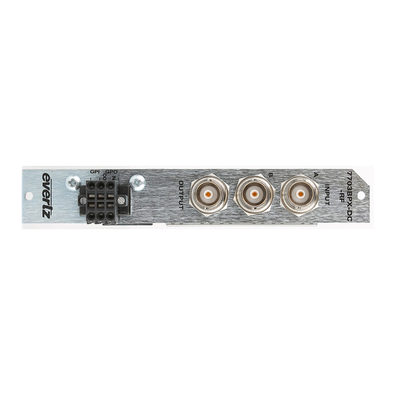
2X1 RF Protection Switch INSTALLATION The 7703BPX-DC-RF comes with a companion rear plate that has three BNC (F type optional) connectors and a six pin terminal strip. For information on mounting the rear plate and inserting the module into the frame see section 3 of the 7700FR chapter. -
Page 12: Gpio
7703BPX-DC-RF 2X1 RF Protection Switch 2.1. GPIO A 6-pin removable terminal block labeled GPIO contains 2 GPI inputs and 2 GPO outputs GPI’s: The two top pins on the 6 pin terminal strip are used for two General Purpose inputs (GPI). -
Page 13: Specification
7703BPX-DC-RF 2X1 RF Protection Switch SPECIFICATION 3.1. RF INPUT/OUTPUT Inputs Outputs Connectors 1 BNC per IEC 61169-8 Annex A (F type and SMA optional) 75Ω, 50Ω optional I/O Impedance Frequency Response 10MHz - 2250MHz < ±0.75dB Insertion Loss 10MHz - 2250MHz <... -
Page 14: Electrical
7703BPX-DC-RF 2X1 RF Protection Switch 3.4. ELECTRICAL Voltage +12VDC Power 4 Watts EMI/RFI Complies with FCC regulations for class A devices Complies with EU EMC directive 3.5. PHYSICAL 350FR 7700FR-C 7800FR 7801FR Page 6 Revision 1.0... -
Page 15: Status Indicators And Displays
2X1 RF Protection Switch STATUS INDICATORS AND DISPLAYS The 7703BPX-DC-RF has 9 LED Status indicators on the front card edge to show operational status of the card at a glance. The 7703BPX-DC-RF also has an alphanumeric dot matrix display, toggle switch and push button. - Page 16 7703BPX-DC-RF 2X1 RF Protection Switch Additional signal and status monitoring and control over the card’s parameters are provided via the 4-digit alphanumeric display located on the card edge. To select one of two menu display modes, press the toggle switch. To go to the sub-menu press the pushbutton once to select the sub-menu display and then press the toggle switch.
-
Page 17: Displaying The Rf Power Of Input A And Input B
4.2.1. Displaying the RF Power of Input A and Input B The 7703BPX-DC-RF detects the input RF power of both inputs and displays this on the four-digit card edge display. Enter the MON menu item, then toggle to PWRA or PWRB and press the pushbutton. -
Page 18: Displaying The Firmware Version
7703BPX-DC-RF 2X1 RF Protection Switch The following list describes the possible displays and their significance: MODE Indicates Auto – No switch back AUTO AUTO Indicates that A is active channel Indicates external (GPI) mode status CH A Indicates external mode status... -
Page 19: Selecting High Or Low As Gpi Active State
Table 4-2: Controlling the Switch Using GPI Inputs – 7703BPX-DC-RF 4.2.7. Selecting High or Low as GPI Active State The 7703BPX-DC-RF allows setting the Active state of the GPIs as high or low. Enter the SET menu and toggle to the ACTV menu item. -
Page 20: Performing A Factory Reset
2X1 RF Protection Switch 4.2.10. Performing a Factory Reset The 7703BPX-DC-RF enables the user to perform a factory reset of card parameters. Enter the SET menu and navigate to the FRST menu item, then toggle to ‘YES’ and hit the pushbutton. This restores the default parameters of the card. -
Page 21: Jumpers
POWER +12V +12V EVERTZ 7700BPX-RF Figure 5-1 : Location of Jumpers – 7703BPX-DC-RF 5.1. SELECTING WHETHER LOCAL FAULTS WILL BE MONITORED BY THE GLOBAL FRAME STATUS The FRAME STATUS jumper J9 located near the top front of the module determines whether local faults (as shown by the Local Fault indicator) will be connected to the 7700FR frame's global status bus. -
Page 22: Selecting The Gpi Pull-Up Voltage
7703BPX-DC-RF 2X1 RF Protection Switch To upgrade the firmware in the module unit pull it out of the frame. Move the UPGRADE jumper into the UPGRADE position. Install the Upgrade cable provided (located in the vinyl pouch in the front of this manual) onto the SERIAL header J14 at the card edge. -
Page 23: Vistalink ® Remote Monitoring/Control
3. A virtual database known as the Management Information Base (MIB) lists all the variables being monitored, which both the Manager and Agent understand. Please contact Evertz for further information about obtaining a copy of the MIB for interfacing to a third party Manager/NMS. -
Page 24: Vistalink Controlled Parameters
7703BPX-DC-RF 2X1 RF Protection Switch 6.3. VISTALINK CONTROLLED PARAMETERS ® The following parameter can be remotely controlled through the VistaLINK interface. ® Parameter Description Sets the operating mode for the module: o External ( Controlled by GPIs ) o Auto / No Switch Back...
Need help?
Do you have a question about the 7703BPX-DC-RF and is the answer not in the manual?
Questions and answers