Table of Contents
Advertisement
Quick Links
Advertisement
Table of Contents

Related Manuals for STEINEL S-Former E


Summary of Contents for STEINEL S-Former E
- Page 1 Instruction manual Control unit S-Former E...
-
Page 3: Table Of Contents
Labelling of the control unit and the components ......... 8 Safety signs ..................8 Identification plate ................. 8 Design and function ............9 Tapping system S-Former E ..............9 Control unit .................... 9 Control cabinet ..................9 Connections on the control cabinet ............ 10 Components in the control cabinet ............. - Page 4 IP addresses ................. 70 6.6.3.8 Signal logic ................... 72 6.6.3.9 Fault signal ................... 72 6.6.3.10 Drive parameters ................ 73 Date/Time ..................74 Help ....................75 6.6.5.1 Instructions ................... 75 6.6.5.2 Remote maintenance ..............75 OI Control unit for S-Former E...
- Page 5 Signal flow diagram ................110 Maintenance, repair ............ 112 Safety instructions ................112 Maintenance schedule ..............114 Disposal ............... 115 Technical data ............. 116 List of symbols ............119 List of figures .............. 122 OI Control unit for S-Former E...
- Page 6 Table of contents OI Control unit for S-Former E...
-
Page 7: User Guide
User guide Purpose of the operating instructions These operating instructions are part of the control unit for the S-Former E. They facilitate the safe handling of the control unit. The instructions of component suppli- ers and local accident prevention regulations also apply. -
Page 8: Display Of Warnings
This signal word indicates a potentially dangerous situation. Failure to comply with safety regulations may result in damage to the product or environmental damage. Notes, tips and recommendations as well as information on efficient and failure- free operation. OI Control unit for S-Former E... -
Page 9: Safety Symbols Used
There is a risk of injury from moving machine parts. This symbol indicates a "Warning of a hot surface". Exposure to hot surfaces may result in burns. This symbol indicates a "Warning of tipping hazard". Take care when handling the top-heavy control cabinet. OI Control unit for S-Former E... -
Page 10: Safety
The control unit is used to operate, control, set up and parametrise the S-Former-E system. The control unit may only be used in connection with tapping units of the type S-Former E with AC servomotor and it is intended for integration into a super- ordinate machine and a superordinate control unit. -
Page 11: Dangers When Handling The Control Unit
– Operation of the control unit with connected loads different from those stated in Chapter 9, Technical data, Page 116. – Connection of devices other than the tapping units of the type S-Former E. – Unauthorised additions, modifications or changes to the control cabinet and the PLC. - Page 12 The motor and the roll tap can become very hot during operation. There is a risk of burns. Do not touch the components or wear safety gloves. Allow the components to cool down to room temperature prior to touching them. OI Control unit for S-Former E...
-
Page 13: Owner Obligations
All persons tasked with working at the components commit to – observe basic regulations concerning occupational safety and accident preven- tion, – read and observe the safety chapter and the safety instructions of these operat- ing instructions prior to beginning work. OI Control unit for S-Former E... -
Page 14: Labelling Of The Control Unit And The Components
The identification plate is affixed to the control cabinet. Fig. 2-1 Identification plate The identification plates of the individual components can be found on these com- ponents as well as the documentation of the respective manufacturer. OI Control unit for S-Former E... -
Page 15: Design And Function
Design and function Tapping system S-Former E The tapping system S-Former E is used for the automated production of internal threads in prepared parts. Roll tap heads in various sizes are available for machin- ing depending on the required power and torque. -
Page 16: Connections On The Control Cabinet
8Connecting socket for lubrication system 9Connecting socket for the signal of the superordinate control unit, e.g. a press 10Main power supply 400 VAC 11Main switch 12EMERGENCY STOP button 13Filter fan inlet 14Outlet plug connection, single version shown here OI Control unit for S-Former E... -
Page 17: Components In The Control Cabinet
5Drive controller with PLC control unit 6Optional: Expansion with LTE router or WLAN for remote maintenance or net- work factory connection Please see the connection diagrams for detailed information on the components in the control cabinet. OI Control unit for S-Former E... -
Page 18: System Design
2–3 bar, is adjustable via the pressure reducer. All plugs and sockets have die-cast aluminium housings with optimised EMC prop- erties and protection class IP65 when plugged in and IP20 when not plugged in. OI Control unit for S-Former E... -
Page 19: Connection Interface For The Cable Set On The Control Cabinet
Socket connection Plug connection 1Connection cable from the control unit to the connection box 2Connection to the connection box 3Connection to the control cabinet Please see the connection diagrams for detailed information on the configuration. OI Control unit for S-Former E... -
Page 20: Connection Box
Connection box side views: Fig. 3-9 Connection box side views, left, front, right 1Supply of the pneumatic system into the box 2Switching valve for the pneumatic system 3Outputs for the electrical supply of the switching valve OI Control unit for S-Former E... -
Page 21: Motor Cable Set
1Tapping unit head connections 2Connection box connection Assignment of the connector plug: Fig. 3-11 Motor cable set connector plug 18-pole module for motor power 28-pin GigaBit module for motor encoder 317-pin module for I/Os 4Pneumatic module OI Control unit for S-Former E... -
Page 22: Instructions For Correct Handling Of The Connector Plugs
Correct: Locking clip closed Locking clip Locking clip Incorrect connection: The plug is plugged in, but the locking clips are open. Correct function and safe protection are not provided. Fig. 3-13 Incorrect: Locking clip open OI Control unit for S-Former E... -
Page 23: Function
In the password-protected setup mode, the control unit of the S-Former does not react to the signals of the superordinate control unit. The S-Former E can be oper- ated manually, only individual movements are possible: Disengaging, single stroke, extending the cylinder and measuring. -
Page 24: Process
If a tapping tool is worn, damaged or if the torque was determined to be too high or too low, the unit is stopped and the error message Error 2011 Station 1: Thread NOK! => Acknowledge error is displayed. OI Control unit for S-Former E... -
Page 25: Transportation, Installation, Storage
Transportation Transit damages Check the control unit for transit damages immediately after delivery. The shipping company, the insurance company and STEINEL Normalien AG must be immediately notified of any transit damage. WARNING! The control cabinet is top-heavy. Improper transportation can result in a crushing hazard. -
Page 26: Installation
Storage Ambient conditions Specification Value Permissible temperature range -20 °C to +55 °C Maximum temperature change 10 °C/h Relative humidity 5 to 95 % Condensation not permissible Freezing not permissible OI Control unit for S-Former E... -
Page 27: Assembly
Assembly ATTENTION! The control unit is delivered solely as a component of the tapping unit S-Former E and may only be operated in connection with it. As owner it is your responsibility to safely integrate the control unit into the entire system as well as the production process. - Page 28 – In order to prevent an unexpected start, the superordinate control unit may not send a permanent start signal to the control unit of the S-Former E. – Secure open interfaces with suitable covers.
-
Page 29: Operation Of The Plc
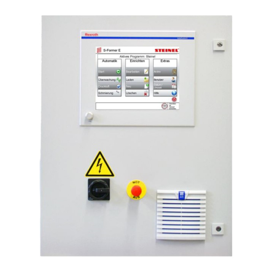
The start screen of the PLC user interface appears on the touch screen. Start-up screen Fig. 6-1 Start-up screen of the PLC user interface The main menu, the top level of the user interface, is then displayed, Chapter 6.3, Main menu, Page 26. OI Control unit for S-Former E... -
Page 30: Starting The Automatic Mode
Prior to confirmation, make sure that there are no persons in the danger area. Fig. 6-2 Warning message ⚫ Select the "Confirm" button. ⚫ Select the "Stop" button in the footer of the program window to stop the move- ment. OI Control unit for S-Former E... -
Page 31: Starting The Setup Mode
Prior to confirming the message, make sure that there are no persons in the dan- ger area, e.g. those performing maintenance tasks. Fig. 6-3 Warning message ⚫ Select the "Confirm" button. ⚫ Select the "Stop" button in the footer of the program window to stop the move- ment. OI Control unit for S-Former E... -
Page 32: Main Menu
The header is used as a pure information line and always contains the thread symbol, Chapter 6.3.2, Functions of the thread symbol, Page 27. Action area The selected menu is displayed. Footer The footer is used as a navigation and function line. OI Control unit for S-Former E... -
Page 33: Functions Of The Thread Symbol
To protect the system, the unit and other equipment, the execution of all drive movements is stopped until the error has been acknowledged and/or eliminated. A "Reset drives" ( PLC diagnostics ) may be required. Fig. 6-5 Functions of the thread symbol OI Control unit for S-Former E... -
Page 34: Structure Of The Main Menu
Detailed information on the functions can be found here: Automatic: Chapter 6.4, Automatic, Page 29 Setup: Chapter 6.5, Setup, Page 39 Extras: Chapter 6.6, Extras, Page 56 Structure chart Fig. 6-7 Structure chart of the main menu OI Control unit for S-Former E... -
Page 35: Automatic
, Page 38 Compressed air menu item Chapter Fehler! Verweisquelle konnte nicht gefunden werden., Pneumatic , Page Fehler! Textmarke nicht definiert. Lubrication menu item Chapter 6.4.5, Lubrication , Page 38 Fig. 6-8 "Automatic" menu OI Control unit for S-Former E... -
Page 36: Start
Chapter 6.7, Process monitoring , Page 77. The graph shows the trend progression of the station, Chapter 6.4.2.4, Trend progression and setting , Page Additional functions for evaluation. OI Control unit for S-Former E... - Page 37 , Page 60. Calling up the history, Chapter 6.4.2.3, History , Page Calling up the trend settings, Chapter 6.4.2.4, Trend progression and setting , Page 35. "Start" structure chart Fig. 6-10 "Start" structure chart OI Control unit for S-Former E...
-
Page 38: Status Window
Indicates that a limit value has been exceeded at this station and that the process is NOK. However, there may also be another error at this station. The error must be acknowledged. Fig. 6-14 Status=3 OI Control unit for S-Former E... -
Page 39: History
In addition, all recorded curves can be displayed on top of one another for easier analysis of changes and scattering of the individual curves. Functions such as Zoom, Navigation and Save are also available. OI Control unit for S-Former E... - Page 40 – signs of wear on the tapping unit head The cause of the scattering can be determined from the curve and by adjusting and changing various parameters and trials. Fig. 6-19 Complete display of history curves OI Control unit for S-Former E...
-
Page 41: Trend Progression And Setting
The maximum torque value is determined during a tapping process. The deter- mined value is displayed on the graph. There is a value for each tapping process. The graph is permanently displayed in the status window. Fig. 6-21 Trend progression OI Control unit for S-Former E... - Page 42 – Correct parametrisation for calculating the theoretical torque – Mechanical damage to the tapping unit head, no thread has been tapped – Roll tap condition (broken) Touching the symbol opens a window for setting the trend display. OI Control unit for S-Former E...
- Page 43 , Page 58. Monitoring: The maximum limit is monitored and an error is output if it is exceeded. The minimum limit value is always monitored. Display duration (X-axis) adjustable in hours, minutes and seconds. OI Control unit for S-Former E...
-
Page 44: Monitoring
This function enables manual control of the lubrication. The lubrication remains on until it is switched off again by the same switch or another function is selected in the main menu. Fig. 6-25 Lubrication on Fig. 6-26 Lubrication off OI Control unit for S-Former E... -
Page 45: Setup
Load menu item Chapter 6.5.3, Load , Page 53 New menu item Chapter 6.5.4, New , Page 53 Delete menu item Chapter 0, Delete , Page 56 Fig. 6-27 "Setup" menu OI Control unit for S-Former E... -
Page 46: Edit
3Parametrisation area 4"Back" button 5Station selection 6"Start" button 7"Save" button The "Start" button is only displayed when the tapping unit head sizes stored in the program match those of the connected tapping unit head sizes. OI Control unit for S-Former E... - Page 47 Navigation to the previous page. Currently selected station, selection of another station (if available). Starting a tapping cycle for all active tapping units. Saving of the settings made. "Edit" structure chart Fig. 6-29 "Edit" structure chart OI Control unit for S-Former E...
-
Page 48: Station" Tab
The pitch refers to the number of windings over the length of one inch. Example of UNF 7/16"-20: Diameter: 7/16" * 25.4 mm = 11.1125 mm Pitch: 1" / 20 = 25.4 mm / 20 = 1.27 mm OI Control unit for S-Former E... -
Page 49: Pneumatics" Tab
S-Former-E control unit. Advanced Advanced setting options, Advanced pneumatic settings, Page 44. Retract Manually retract spindle Extend Manually extend spindle Vent Depressurise the pneumatic cylinder OI Control unit for S-Former E... - Page 50 6Symbolisation of piston, spindle and roll tap 7Blue: "Compressed air off" switching point Advanced pneumatic settings The signal processing can be influenced and adapted in the advanced pneumatic settings. Fig. 6-33 Advanced pneumatic settings OI Control unit for S-Former E...
- Page 51 0.0 V and the direction lower end position a value of approx. 10.0 V. However, only the displayed value is changed; the actual measured value of the sensor is not affected. OI Control unit for S-Former E...
-
Page 52: Drive" Tab
(±150 ms). Otherwise, check that the tool/press is in the corresponding angular position or that the installation position of the tapping unit head is correct. OI Control unit for S-Former E... - Page 53 Red: Load high, a thermal overload will occur if the rest period is not sufficient. Increased mechanical wear. The operation should be within the green range. The yellow and red ranges should be reserved for time-critical applications. The input values are limited to protect the mechanical system. OI Control unit for S-Former E...
- Page 54 Only the compliance with the mechanical limits is checked. The thermal load and durability can only be determined and displayed in automatic mode. OI Control unit for S-Former E...
-
Page 55: General" Tab
Sets the quantity back to "0". Lubrication If a lubrication system, spray unit or minimum quantity lubrication (MQL) is connected to the S-Former-E control unit, the control times can be defined, Chapter 6.4.5, Lubrication , Page 38. OI Control unit for S-Former E... - Page 56 This message does not, however, stop the tapping pro- cess. The message remains until the level is OK again. Fig. 6-39 "Lubrication setting" window OI Control unit for S-Former E...
- Page 57 Otherwise the lubricant could drip off the roll tap during the waiting time. As with intermediate lubrication I, the spray nozzle must be aligned with the roll tap. Delayed lubrication on roll tap OI Control unit for S-Former E...
- Page 58 A check for sufficient and continuous lubricant delivery is necessary at all connected nozzles each time the unit is put into service and in the event of faults or refilling of the lubricant tank. OI Control unit for S-Former E...
-
Page 59: Load
⚫ Select the "New" menu item. Fig. 6-41 "Create new program, select template" window ⚫ Select a template in the "Create new program, select template" window. ⚫ Press "Create". OI Control unit for S-Former E... - Page 60 Type Corresponds to the press strokes per minute. Designation Press angle at which the press control unit outputs the start signal to the S-Former-E control unit. Fig. 6-44 Wizard for program creation II OI Control unit for S-Former E...
- Page 61 ⚫ Once all entries have been made, exit the wizard using the green arrow. The program is created. The "Edit" menu then opens. Further fine adjustments can be made here. Chapter 6.5.2, Edit , Page 40. OI Control unit for S-Former E...
-
Page 62: Delete
, Page 57 User menu item Chapter 6.6.3, User , Page 63 Date/Time menu item Chapter 6.6.4, Date/Time , Page 74 Help menu item Chapter 6.6.5, Help , Page 75 Fig. 6-47 "Extras" menu OI Control unit for S-Former E... -
Page 63: Archive
In this way, all measurement curves of a date of the same program can be analysed. Fig. 6-49 "Measurement curves archive" window 1Graph/measurement curves 2Navigation 3Program 4Date 5Table OI Control unit for S-Former E... -
Page 64: Trend Progression
The display range of the graph indicates the status of the batch counter. If the batch counter was reset during a production run within one day, a new file is cre- ated for the trend progression data. OI Control unit for S-Former E... - Page 65 Selection table for selecting the trend progression to be displayed Selection table Date Date of the progression data Begin Start of recording (time) End of recording (time) Strokes Number of recorded tapping processes OI Control unit for S-Former E...
-
Page 66: Statistics
The following evaluations are available: Daily production overview Fig. 6-52 "Daily production" window Each point describes the production and error message quantity within one hour. Y-axis = production quantity X-axis = hour (0 – 23 hours) OI Control unit for S-Former E... - Page 67 X-axis = day (1 to 31) Annual production overview Fig. 6-54 "Annual production" window Display of the entire monthly production over the period of one year. Y-axis = production quantity X-axis = month (1 to 12) OI Control unit for S-Former E...
-
Page 68: Log Protocol
The following information is logged: Fig. 6-56 Log protocol table OI Control unit for S-Former E... -
Page 69: User
The "User" menu is used to log a user on and off and to set the language. ⚫ Select the "User " menu item. Fig. 6-57 "User/Language" menu Further system settings are available as of the Setter user group, Chapter , Page 65, . 6.6.3.3 System settings OI Control unit for S-Former E... -
Page 70: Log In User, Select Language
− Service SNAG1948 For customer-side service personnel, no restrictions, even closing the application and access to Windows Admin − Reserved for STEINEL Normalien AG service personnel ⚫ Select the "Confirm" button. OI Control unit for S-Former E... -
Page 71: System Settings
IP addresses, signal logic, fault signal and drive parameters. Fig. 6-59 System settings Information on the individual menu items can be found here: User administration Chapter 6.6.3.4, User administration , Page 68 Data backup Chapter 0, OI Control unit for S-Former E... - Page 72 IP addresses Chapter 6.6.3.7, IP addresses , Page 70 Signal logic Chapter 6.6.3.8, Signal logic , Page 72 Fault signal Chapter 6.6.3.9, Fault signal , Page 72 Drive parameters Chapter 6.6.3.10, Drive parameters , Page 73 OI Control unit for S-Former E...
- Page 73 6 Operation of the PLC System settings structure chart Fig. 6-60 System settings structure chart OI Control unit for S-Former E...
-
Page 74: User Administration
Creating a user To change the password for an existing user, select the relevant user. Fig. 6-63 Changing a user To delete an existing user, select the relevant user. Fig. 6-64 Deleting a user OI Control unit for S-Former E... -
Page 75: Data Backup
If the backup failed because the storage path did not exist or was write-protected, the backup will not be repeated. Fig. 6-66 Backup interval The internal flash card cannot be used as a backup path because it is write-pro- tected. OI Control unit for S-Former E... -
Page 76: Program Data
If the control unit is operated in a network, the IP address of the panel can option- ally be obtained dynamically. If the control unit is not integrated in a network, a static IP address must be used. Only a static IP address can be used for the PLC. OI Control unit for S-Former E... - Page 77 IP as well as operation and communication with the PLC via the second network card with static IP. Parametrisation of the net- work addresses is therefore not absolutely necessary. OI Control unit for S-Former E...
-
Page 78: Signal Logic
It can also be output after a delay to prevent parts man- ufactured before the fault from being lost. The following functions can be set: Fig. 6-71 Fault signal setting OI Control unit for S-Former E... -
Page 79: 6.6.3.10 Drive Parameters
Data records for the drive controllers can be loaded into the control unit using the "Load parameters" function. These must be correct in content, form and format, otherwise this leads to a serious fault up to total failure! Fig. 6-72 Drive parameters OI Control unit for S-Former E... -
Page 80: Date/Time
A deviation of time and date can occur after a period of non-use of five days. Check the date and time before each use. The date is set in day/month/year. Fig. 6-75 Setting the date OI Control unit for S-Former E... -
Page 81: Help
IP. For VEP40.4 panels with Windows XP, only one network card is available. In this case, the IP addresses must be adapted both by the panel and by the PLC. OI Control unit for S-Former E... -
Page 82: Information
Page 70. Fig. 6-78 Remote maintenance 6.6.5.3 Information This menu displays contact data such as address, telephone number, e-mail ad- dress and version information for the user interface and PLC control unit. Fig. 6-79 Information OI Control unit for S-Former E... -
Page 83: Process Monitoring
Zooming, vertical and horizontal zoom 100% view: The measurement and tolerance curve is zoomed in the X- and Y-directions until the curve fills the entire graph. Complete view: The curve is reduced to the origin again. OI Control unit for S-Former E... - Page 84 Description Activate (On) and deactivate (Off) process monitoring Call up the menu for setting the monitoring, Chapter 0 Setting process monitoring , Page 80. Process monitoring structure diagram Fig. 6-81 Process monitoring structure diagram OI Control unit for S-Former E...
-
Page 85: Measurement Ok
If the automatic saving of error measurement curves is not deactivated, error measurement curves are automatically saved and stored in the archive. They can be displayed and tracked at any time via the archive function. Manual saving is not necessary. Fig. 6-83 Measurement NOK OI Control unit for S-Former E... -
Page 86: Setting Process Monitoring
The maximum monitoring time corresponds to the maximum process time that can be entered in setup mode, Chapter 6.5, Setup, Page 39. OI Control unit for S-Former E... -
Page 87: Setting The Tolerance
The zero point tolerance is set according to the application. For generally low tor- ques, a lower value should be set; for generally higher torques, a higher value can be set. Fig. 6-86 Zero point tolerance OI Control unit for S-Former E... - Page 88 Example of low tolerance Upper tolerance: 10 % Lower tolerance: 7 % Zero point tolerance: 0.05 Nm Fig. 6-88 Example of high tolerance Upper tolerance: 70 % Lower tolerance: 50 % Zero point tolerance: 0.5 Nm OI Control unit for S-Former E...
-
Page 89: Smoothing
Example of low smoothing Measured value: 1 ms Upper tolerance: 1 ms Lower tolerance: 1 ms Too little smoothing of the measured values leads to a fault, as no peaks and fluc- tuations are filtered and smoothed. OI Control unit for S-Former E... - Page 90 Measured value: 20 ms Upper tolerance: 3 ms Lower tolerance: 3 ms The measured value is sufficiently smoothed in order to suppress peaks and fluctu- ations while maintaining a good simulation of the process. OI Control unit for S-Former E...
-
Page 91: Widening
The setting values for the widening can range from 2 % to 20 % depending on the requirements and application. Fig. 6-94 Example of low widening Upper tolerance: 5 % Lower tolerance: 5 % OI Control unit for S-Former E... -
Page 92: Window Function
4Outlet range Pos. Description Inlet range From time 0 to defined time. Middle range From defined to defined time. Inlet range From time 0 to defined time. Outlet range From defined to end time. OI Control unit for S-Former E... -
Page 93: Checking And Sending Settings
The settings made can be checked before they are sent to the PLC. For this pur- pose, a preview is opened in which the tolerance curve has already been adapted to the inputs. The preview opens with the "Adapt" function in the "Settings" menu. Fig. 6-98 "Settings" menu OI Control unit for S-Former E... -
Page 94: Plc Diagnostics
Further functions are "Reset drives", "Acknowledge error", "Retract units" and "Connect FTP", Chapter 6.8.1, Overview, Page 90. In addition, further information about the drive controllers and the switching states of the PLC inputs and outputs can be queried, Chapter 0, OI Control unit for S-Former E... - Page 95 6 Operation of the PLC Drive data to 0, OI Control unit for S-Former E...
-
Page 96: Overview
Fig. 6-101 C1600 command message line The axis is only deactivated if no tapping unit head and a "Reset drives" is carried out or the control unit is switched on. OI Control unit for S-Former E... - Page 97 6 Operation of the PLC The axis is only activated when a tapping unit head is connected and a "Reset drives" is carried out or the control unit is switched on. OI Control unit for S-Former E...
- Page 98 – If no connection can be established despite correct IP addressing, switch the control unit off and on again. If the problem persists, check the settings of the IP addresses of the PLC and control panel, Chapter 6.6.3.7, IP addresses , Page 70. OI Control unit for S-Former E...
-
Page 99: Drive Data
Operation above 100 % leads to a thermal overload that can occur prematurely or delayed depending on the load. Active Describes the tapping unit head with motor detected on the drive motor in and the drive parameters loaded in the drive. the drive OI Control unit for S-Former E... -
Page 100: Plc Communication
Connector plug for communication with a higher-level control unit with inputs and outputs as well as incoming emergency stop signal. -40XS4 Connector plug for outgoing emergency stop signal. -40XS6 Connector plug for controlling a lubrication system/oiler. OI Control unit for S-Former E... -
Page 101: Plc Outputs
The figure refers to the I/O block located in the control cabinet and shows the cur- rent states of the outputs Output 1 to Output 16 on two diagnostic pages. Fig. 6-106 PLC outputs O1–O8 Fig. 6-107 PLC outputs O9–O16 OI Control unit for S-Former E... -
Page 102: Plc Inputs
The figure refers to the I/O block in the control cabinet and shows the current states of the inputs Input 1 to Input 16 on two diagnostic pages. Fig. 6-108 PLC inputs I1–I8 Fig. 6-109 PLC inputs I9–I16 OI Control unit for S-Former E... -
Page 103: Tips And Notes For Using Monitoring
If the maximum process time is set too high, the output of the error signal is too delayed; a timely press stop cannot be achieved. OI Control unit for S-Former E... -
Page 104: Trend Monitoring
– Tool breakage – Dimensional accuracy and positioning of thread pull-through or threaded hole – Mechanical damage to the tapping unit head so that no thread was tapped Appropriate limits must be determined by tests. OI Control unit for S-Former E... -
Page 105: Envelope Monitoring
The settings are dependent on the application and requirement. Examples of permissible tolerance: Fig. 6-114 Small tolerance Small tolerance values: Very close fitting envelope, smallest deviations lead to error messages. OI Control unit for S-Former E... - Page 106 Higher smoothing values suppress peaks and jumps in the torque curve and a more even curve is generated. If the smoothing is set too high, relevant changes in the torque curve are sup- pressed and the monitoring becomes less accurate. OI Control unit for S-Former E...
- Page 107 Window 1, max. limit: Drive acceleration at the beginning of the tapping process Window 2, min. limit: Drive acceleration at the beginning of the tapping process Window 3, max. limit: Drive acceleration during reverse travel OI Control unit for S-Former E...
-
Page 108: Documentation For Data Management
The following grading takes place: Recording duration Sampling up to 1399 ms 4 ms up to 2799 ms 8 ms up to 4199 ms 12 ms up to 5599 ms 16 ms from 5600 ms 32 ms OI Control unit for S-Former E... -
Page 109: Reference Curve
Path: Drive:\Steinel\S-Former_E\Archive\Archive\ Program name\Year\Month\Day\File Specifications set in italics are variable. Example: Drive = D:\ Program name = Steinel Year = 2016 Month = 05 Day = 04 => results in a path: D:\Steinel\S-Former_E\Archive\Archive\Steinel\2016\05\04\... OI Control unit for S-Former E... - Page 110 Number of lines The number of lines results from the recording duration (monitoring time) and the sampling rate. => a line can appear as follows: 0120;1.5500;2.05;-0.25;-99.99 Measurement curve within tolerance 0124;2.5500;1.05;-1.25;2.55 Measurement curve out of tolerance OI Control unit for S-Former E...
-
Page 111: History
Number of strokes (number of start processes) Number of threads (addition of all stations) Axis 1 quantity Axis 2 quantity Axis 3 quantity Axis 4 quantity 5674 State of the batch counter at the time of saving OI Control unit for S-Former E... - Page 112 Segment Description Number of error strokes Number of error threads (addition of all stations) Number of axis 1 errors Number of axis 2 errors Number of axis 3 errors Number of axis 4 errors OI Control unit for S-Former E...
- Page 113 Description Month Number of error strokes Number of error threads (addition of all stations) Number of axis 1 errors Number of axis 2 errors Number of axis 3 errors Number of axis 4 errors OI Control unit for S-Former E...
-
Page 114: Trend
Day of the trend data 2 characters, current day Hour 2 characters, current hour 2 characters, current Separation with "-" Minute minute Start of recording 2 characters, current Second second => results in a file: Steinel#####_2016-05-04_11-15-08.txt OI Control unit for S-Former E... -
Page 115: Log Protocol
Diagnostics code for axis status, connected tapping unit head (-- not active) Diagnostics code for axis status, connected tapping unit head (-- not active) Diagnostics code for axis status, connected tapping unit head (-- not active) Stroke speed 28253 Quantity OI Control unit for S-Former E... -
Page 116: Signal Flow Diagram
6 Operation of the PLC Signal flow diagram The following signal flow diagrams show typical communication examples between a higher-level control system and the S-Former-E control unit. Fig. 6-120 Signal flow diagram OI Control unit for S-Former E... - Page 117 The program may only be restarted after the cause of the error has been eliminated and the er- ror has been acknowledged. Fig. 6-121 "Fault" signal flow diagram OI Control unit for S-Former E...
-
Page 118: Maintenance, Repair
(supplied products, pur- chased parts, supplier, OEM). Notify the operating personnel prior to the start of the tasks and place a sign at the control cabinet while the tasks are performed. OI Control unit for S-Former E... - Page 119 Allow the components to cool down to the ambient temperature prior to beginning the tasks. ATTENTION! In case of a defect or a fault of the control unit, please contact STEINEL Normal- ien AG. A repair or a replacement of components may only be carried out by trained per- sonnel of STEINEL Normalien AG.
-
Page 120: Maintenance Schedule
Check the function of the Emergency Stop device and all protective devices as per a danger assessment or at least Observe the safety and testing parameters in Chapter 9, Technical data. OI Control unit for S-Former E... -
Page 121: Disposal
– Sort the remaining components according to material type prior to disposal. If in doubt, contact your local government or specialised disposal companies how to dispose of your material in an environmentally friendly manner. OI Control unit for S-Former E... -
Page 122: Technical Data
15 g for 11 ms Condensation and ice not permitted -20 – +55 °C Storage temperature The ambient air must be free of higher concentrations of acids, alkalis, corrosives, salt, dust, metal vapours and other electrically conductive contamination. OI Control unit for S-Former E... - Page 123 Interfaces Emergency stop input/output for safe drive shutdown 2-channel Press communication emergency stop input 12-pin Control of lubricator, lubrication system, minimum quantity lubrication system 6-pin Emergency stop output 6-pin 1 piece Ethernet 2 pieces OI Control unit for S-Former E...
- Page 124 Contactors dropout time min./max. 0.1 s (cutting of the power supply (or set value of the drives) Compressed air dropout time immediately, without delay (cutting of the voltage supply of the compressed air valve) OI Control unit for S-Former E...
-
Page 125: 10 List Of Symbols
Envelope monitoring Edit an existing program Load an existing program Create a new program Delete an existing program Start archive mode Measured values archive mode Log protocol archive mode User System settings User administration OI Control unit for S-Former E... - Page 126 Export data to a different location and in a different format Navigation arrows Navigate left, up, down, right Zoom Horizontal and vertical zoom 100 % view Set view to full size Initial size Set view to initial size OI Control unit for S-Former E...
- Page 127 Status display of PLC inputs or outputs Green: Signal present Red: No signal present Signal logic: Rising/falling edge Thread symbol: No message pending Thread symbol: Warning message pending Thread symbol: Error pending OI Control unit for S-Former E...
-
Page 128: 11 List Of Figures
"Lubrication setting" window ................50 Fig. 6-40 "Load program" window..................53 Fig. 6-41 "Create new program, select template" window ..........53 Fig. 6-42 "Program name" window ................... 54 Fig. 6-43 Wizard for program creation I ................54 OI Control unit for S-Former E... - Page 129 C1600 command message line ................90 Fig. 6-102 Function line ....................... 92 Fig. 6-103 Additional function for service - input of the PLC address ......... 92 Fig. 6-104 Drive data ......................93 Fig. 6-105 PLC communication ................... 94 OI Control unit for S-Former E...
- Page 130 Fig. 6-117 Heavy smoothing ..................... 100 Fig. 6-118 No window function ..................101 Fig. 6-119 Window function active ..................101 Fig. 6-120 Signal flow diagram ..................110 Fig. 6-121 "Fault" signal flow diagram ................111 OI Control unit for S-Former E...
- Page 132 Telefon +49 7720 6928-0 Fax +49 7720 6928-970 info@steinel.com www.steinel.com We cannot accepl any liabilily for errors and mislakes. We reserve lhe righl to make technical changes as progress brings improvement and changes in construction, measurements and materials. Copyright STEINEL Normalien AG...
Need help?
Do you have a question about the S-Former E and is the answer not in the manual?
Questions and answers