Table of Contents
Advertisement
Quick Links
Advertisement
Table of Contents

Subscribe to Our Youtube Channel
Related Manuals for STEINEL S-Former E


Summary of Contents for STEINEL S-Former E
- Page 1 Assembly instructions for S-Former E...
- Page 2 Germany Phone +49 7720 6928-0 Fax +49 7720 6928-970 info@steinel.com www.steinel.com Copyright STEINEL Normalien AG All rights reserved. Assembly instructions Edition 1 English Date of issue 12/2022 Changes to the design and product that serve to improve the product remain reserved.
-
Page 3: Table Of Contents
Dangers when handling the S-Former E S-Former E identification 3 Function Functional description S-Former E control unit S-Former E control unit with the STEINEL S-Former E control unit 4 Design according to type S-Former E types 4.1.1 S-Former E0 4.1.2 S-Former E1.1... - Page 4 5 Transport, storage Transport information Storage information 6 Electrical installation Safety instructions Connecting the S-Former E to the STEINEL S-Former E control unit Connecting the S-Former E to an external control unit Connecting the AC Servodrive 6.4.1 General procedure 6.4.2 Kollmorgen AKM1 to AKM7 type 6.4.3...
- Page 5 Table of contents S-Former E1.1 9.3.1 Changing the tool 9.3.2 Changing the tool size S-Former E1.1SSP 9.4.1 Changing the tool 9.4.2 Changing the tool size S-Former E1.2 9.5.1 Changing the tool 9.5.2 Changing the tool size S-Former E2 9.6.1 Changing the tool 9.6.2 Changing the tool size S-Former E3...
- Page 6 Table of contents 11 Disposal 12 Technical data 12.1 Performance data, limits, lifetime 12.1.1 S-Former E0 12.1.2 S-Former E1.1 12.1.3 S-Former E1.1SSP 12.1.4 S-Former E1.2 12.1.5 S-Former E2 12.1.6 S-Former E3 12.2 Drawings and parts lists 12.2.1 S-Former E0 12.2.2 S-Former E1.1SSP 12.2.3 S-Former E1.2 12.2.4 S-Former E2 12.2.5 S-Former E3...
-
Page 7: Introduction
Only commission the S-Former E unit after you have read and understood the assembly instructions. By installing and using the S-Former E, you confirm that you are aware of the unit’s intended use and any potential dangers, have read and fully understood the safety instructions, and are aware of the required maintenance and servicing measures in order to ensure sustained safety and functionality. -
Page 8: Warranty And Liability
ƒ non-intended use of the S-Former E ƒ improper assembly, commissioning, operation, maintenance and inspection of the S-Former E ƒ operating the S-Former E with defective safety equipment or protective devices that were not installed properly or protective devices and/or safety equipment that does not work. -
Page 9: Symbols In These Operating Instructions
Introduction Symbols in these operating instructions 1.5.1 Danger warning levels Various signal words and colours are used depending on the level of risk. DANGER DANGER indicates danger which, if not avoided, has a high chance of resulting in death or serious injury. WARNING WARNING indicates danger which, if not avoided, has a medium chance of resulting in death or serious injury. -
Page 10: Danger Symbols
Introduction 1.5.2 Danger symbols Warning of a danger area Warning of automatic start Warning of hand injuries Warning of hot surface Warning of dangerous electrical voltage 1.5.3 Command symbols Observe instructions for use General warning signs Assembly instructions Version 12.2022... -
Page 11: General Symbols
Numbers in a square with a red frame refer to positions in the figures. Demarcation from the superordinate complete machine We, STEINEL Normalien AG, expressly demarcate ourselves from the direct and indirect dangers posed by the superordinate machine in which The S-Former E is installed. -
Page 12: Safety
Only designated components and accessory parts that have been approved by the manufacturer may be used. Putting the S-Former E into service is prohibited until it has been determined that the machine in which the S-Former E has been installed fulfils all the fundamental requirements of the Machinery Directive. -
Page 13: Foreseeable Misuse
ƒ Operating the S-Former E beyond the defined mechanical and electrical limits ƒ Powering the S-Former E with a type of drive that is different from the one defined ƒ Operating the AC Servodrive with an unsuitable drive control unit ƒ... -
Page 14: Dangers When Handling The S-Former E
Check the electrical connections, plugs and cables before use as well as regularly during operation. In the event of damage, immediately stop the S-Former E until it has been repaired properly. The repairs and inspection must be carried out by electrotechnical experts! WARNING There is a risk of injury from moving machine parts. -
Page 15: S-Former E Identification
Technical data. Ensure that the limits are electronically monitored. S-Former E identification The S-Former E’s identification data is laser-engraved on the front of the housing. Company name Internet address Year of construc- tion (MMYY)/ consecutive serial www.steinel.com... -
Page 16: Function
(also torque-controlled), torque tests for mounted elements etc. The S-Former E can be used for practically all applications for which rotational and free axial movements are required. However, it is not suitable for applications that require the spindle to be moved in an axial direction via a defined feed rate. -
Page 17: S-Former E Control Unit With The Steinel S-Former E Control Unit
The STEINEL S-Former E control unit was specially developed to be used with the S-Former E. A control unit can be used to control up to four S-Former E units regardless of their size (E0, E1.1, E1.2, E3). Each S-Former E can be individually parametrised, and the settings can be saved in programs. You can therefore switch from one production series to the next without incurring a time delay. -
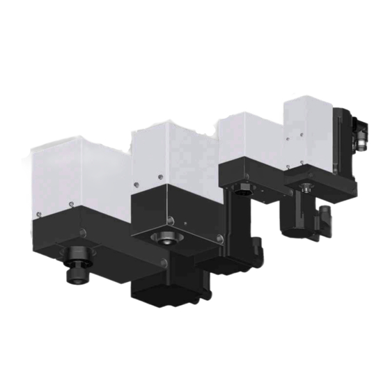
Page 18: Design According To Type
S-Former E types The S-Former E product series consists of 4 basic sizes (E0, E1, E2 and E3) for thread sizes of 1 to 26 mm. Size E1 is available in the variants E1.1, E1.1SSP (not shown here) and E1.2. The S-Former E can also be operated as an independent production unit. -
Page 19: S-Former E1.1
Design according to type 4.1.2 S-Former E1.1 The S-Former E1.1 (part number SZ2701-00001) is operated with a double-stage toothed belt gear. The AC Servodrive has an output of 0.93 kW, while the pneumatic cylinder has a stroke of 30 mm. The tool is clamped with a collet. A reducer enables a length compensation and the square wheel driver. -
Page 20: S-Former E1.1 Ssp
Design according to type 4.1.3 S-Former E1.1 SSP The S-Former E1.1 SSP (part number SZ2701-00004) is operated with a double-stage toothed belt gear. The AC Servodrive has an output of 0.93 kW, while the pneumatic cylinder has a stroke of 30 mm. The tool is picked up by a high-speed clamping system with clamps, length compensation and a square wheel driver. -
Page 21: S-Former E1.2
Design according to type 4.1.4 S-Former E1.2 The S-Former E1.2 (part number SZ2701-00003) is operated with a double-stage toothed belt gear. The AC Servodrive has an output of 0.85 kW, while the pneumatic cylinder has a stroke of 30 mm. The tool is clamped with a collet. A reducer enables a length compensation and the square wheel driver. -
Page 22: S-Former E2
Design according to type 4.1.5 S-Former E2 The S-Former E2 (part number SZ2701-00006) is operated with a double-stage toothed belt gear. The AC Servodrive has an output of 2.6 kW, while the pneumatic cylinder has a stroke of 40 mm. The tool is clamped with a collet. -
Page 23: S-Former E3
Design according to type 4.1.6 S-Former E3 The S-Former E3 (part number SZ2701-00007) is operated with a double-stage toothed belt gear. The AC Servodrive has an output of 2.25 kW, while the pneumatic cylinder has a stroke of 50 mm. The tool is clamped with a collet. -
Page 24: Transport, Storage
Transport, storage Transport information ƒ For transit, ensure that the S-Former E is packaged accordingly to protect against mechanical damage and weather influence. ƒ Protect the S-Former E from excessive shocks and vibrations. Storage information ƒ Store the S-Former E in a dry, clean and oil-free state. -
Page 25: Electrical Installation
When you operate the S-Former E with the STEINEL S-Former E control unit, there are preassembled cable sets available to electrically connect the drive and control unit. The preassembled cable sets are 8 metres long and vary according to the type of S-Former E or drive motor: S-Former type... -
Page 26: Connecting The Ac Servodrive
If you are operating the S-Former E with the STEINEL S-Former E control unit, the 12-pin resolver con- nector must have an S-Former E-typical coding. The free pins 1, 10, 11 and 12 can be used for this. The codings are marked with a * in the following type table. -
Page 27: Beckhoff Am802X Type
Electrical installation 6.4.3 Beckhoff Am802x type S-Former E type E1.2 Motor manufacturer Beckhoff Function iTec-connector, 9-pin n.c. n.c. Thermo+ Thermo- n.c. yTec-connector, 12-pin Coding+* n.c. S3, cos- S4, sin- R2, ref- n.c. S1, cos+ S2, sin+ R1, ref+ Coding* Coding* Coding* 6.4.4... -
Page 28: Coding For The Operation Of A Steinel S-Former E Control Unit
Coding for the operation of a STEINEL S-Former E control unit The coding is required for the operation of a STEINEL S-Former E control unit SZ2700. An uncoded motor will not be recognised, and operating it will not be possible. -
Page 29: Assembly
The fixture should function as a plug-in system with a simple locking feature, particularly when installed in punching tools. The S-Former E should be accessible and removable when the tool is in a fully assem- bled state. -
Page 30: S-Former E0
Assembly S-Former E0 ƒ 2 x adapter sleeves ø12H7 – 5 mm ƒ 2 x socket head screws M5 – 65 mm (lateral) S-Former E1.1 ƒ 4 x M6 – 15 mm thread ƒ 2 x fits ø4H7 – 15 mm on the underside ƒ... -
Page 31: S-Former E1.1 Sssp
Assembly S-Former E1.1 SSSP ƒ 4 x M6 – 15 mm thread ƒ 2 x fits ø4H7 – 15 mm on the underside ƒ 2 x adapter sleeves ø10H7 – 10 mm ƒ 2 x M5 – 75 mm socket head screws (lateral) S-Former E1.2 ƒ... -
Page 32: S-Former E2
Assembly ƒ 2 x alignment pins ø5H7 – 16 mm ƒ 2 x M5 – 75 mm socket head screws (lateral) S-Former E2 ƒ 2 x adapter sleeves ø16H7 – 10 mm ƒ 2 x M8 – 85 mm socket head screws (lateral) S-Former E3 ƒ... -
Page 33: Setup, Putting Into Service
Correctly connect all electrical lines: Specify which version of the S-Former E should be used for each coding. The versions are distinguished by either a motor variant (E0 and E3 with different temperature sensors) or a motor variant and gear ratio (sizes E1.1 and E1.2). -
Page 34: Tool Change
Tool change Safety instructions WARNING Before carrying out any work, disconnect the S-Former E from the elec- trical and pneumatic power supply. Relieve the pressure accumulator. S-Former E0 9.2.1 Changing the tool Spindle Open-end spanner SW10 Clamping nut Tool Hook wrench 1. -
Page 35: S-Former E1.1
Tool change 1. Remove the tool as described in MA, 9.2.1 Changing the tool. 2. Completely unscrew the clamping nut from the spindle 3. Replace the collet 4. During assembly, ensure that the groove (yellow) of the collet engages with the eccentric forming (yellow) of the clamping nut . -
Page 36: Changing The Tool Size
Tool change 9.3.2 Changing the tool size Spindle Reducer Collet Clamping nut Tool Reducer, inner square Collet, groove Clamping nut, formation In order for the tool size to be changed, the collet and the reducer must first be adjusted. 1. Remove the tool as described in MA, 9.3.1 Changing the tool. -
Page 37: S-Former E1.1Ssp
Tool change S-Former E1.1SSP 9.4.1 Changing the tool Spindle High-speed clamping insert, pressure plate Tool 1. Pull out the spindle by hand. 2. Press the pressure plate (yellow) of the high-speed clamping insert 3. Remove the tool 4. Insert the new tool into the high-speed clamping insert. 5. -
Page 38: S-Former E1.2
Tool change Spindle High-speed clamping insert Clamping nut High-speed clamping insert, shaft diameter High-speed clamping insert, square end 4. Remove the high-speed clamping insert from the spindle 5. Insert the new high-speed clamping insert into the spindle so that the carrier wings of the insert become seated in the spindle openings. -
Page 39: Changing The Tool Size
Tool change 9.5.2 Changing the tool size Spindle Reducer Collet Clamping nut Tool Reducer, end square Collet, groove Clamping nut, formation 1. In order for the tool size to be changed, the collet and the reducer must first be adjusted. 2. -
Page 40: S-Former E2
Tool change S-Former E2 9.6.1 Changing the tool Spindle Open-end spanner SW27 Clamping nut Tool Hook wrench 1. Pull out the spindle by hand. 2. Loosen the clamping nut by approx. 1 revolution using the hook wrench and fix the spindle using an SW27 open-end spanner. -
Page 41: S-Former E3
Tool change 5. During assembly, ensure that the groove (yellow) of the collet engages with the eccentric forming (yellow) of the clamping nut . Only this will ensure the proper functioning of the collet. 6. When inserting the tool with the reducer , the collet and clamping nut in the spindle... -
Page 42: Changing The Tool Size
Tool change 9.7.2 Changing the tool size Spindle Reducer Collet Clamping nut Tool Reducer, end square Collet, groove Clamping nut, formation 1. In order for the tool size to be changed, the collet and the reducer must first be adjusted. 2. -
Page 43: Maintenance, Repair
trical and pneumatic power supply. Relieve the pressure accumulator. WARNING All work at the S-Former E may only be carried out by specialist, author- ised personnel. All work at the electrical equipment may only be carried out by qualified electricians. - Page 44 10 Maintenance, repair Work Interval To be carried out by Mechanical repairs, such as the replacement of defective or worn as per requirement Servicing and state parts, e.g.: ƒ Analogue/position sensor ƒ Cylinder ƒ Spindle, spline shaft ƒ Motor ƒ Toothed lock washers ƒ...
-
Page 45: Maintenance Work On The S-Former E0
10 Maintenance, repair 10.3 Maintenance work on the S-Former E0 10.3.1 Cleaning Motor Cover 4x socket-head screws M3x5 4x socket-head screws M5x16 1. Loosen the four M5x16 and M3x5 socket-head screws in order to disassemble the cover and motor. Front assembly group 2x hexagon head screws M5x20 2x socket-head screws M5x12 2. -
Page 46: Retightening Of The Toothed Belt
ATTENTION Do not use any auxiliary aids to tighten the belt. Do not prop up the S-Former E while tightening the screws. 4x socket-head screws M5x16 The toothed belt must be tightened: ƒ semi-annually to annually depending on loads ƒ... - Page 47 10 Maintenance, repair 4x socket-head screws M5x16 2. Hold the S-Former E vertically in the air at the motor . The toothed belt will be sufficiently tightened by the weight force of the front assembly group 3. Slightly twist the spindle so that the toothed belt is seated correctly in the toothing.
-
Page 48: Maintenance Work On The S-Former E1.1
10 Maintenance, repair 10.4 Maintenance work on the S-Former E1.1 10.4.1 Cleaning Cover 4x socket-head screws M4x6 1. Loosen the four M4x6 socket-head screws and disassemble the cover. Front assembly group 4x socket-head screws M4x30 4x socket-head screws M5x20 Housing Rear assembly group 2. -
Page 49: Retightening Of The Toothed Belt
M5x20 sock- et-head screws must be loosened without being removed. 3. Holding the S-Former E at the motor in the air will ensure that the toothed belt is suffi- ciently tightened by the weight force of the front assembly group 4. -
Page 50: Maintenance Work On The S-Former E1.1Ssp
10 Maintenance, repair 10.5 Maintenance work on the S-Former E1.1SSP 10.5.1 Cleaning Cover 4x socket-head screws M4x6 1. Loosen the four M4x6 socket-head screws and disassemble the cover. Front assembly group 4x socket-head screws M4x30 4x socket-head screws M5x20 Housing Rear assembly group 2. -
Page 51: Retightening Of The Toothed Belt
M5x20 sock- et-head screws must be loosened without being removed. 3. Holding the S-Former E at the motor in the air will ensure that the toothed belt is suffi- ciently tightened by the weight force of the front assembly group 4. -
Page 52: Maintenance Work On The S-Former E1.2
10 Maintenance, repair 10.6 Maintenance work on the S-Former E1.2 10.6.1 Cleaning Cover 5x socket-head screws M5x8 1. Loosen the five M5x8 socket-head screws and disassemble the cover. Front assembly group 4x socket-head screws M4x16 4x hexagon head screws M5x20 Housing Rear assembly group 2. -
Page 53: Retightening Of The Toothed Belt
M5x20 hexagon head screws must be loosened without being removed. 3. Holding the S-Former E at the motor in the air will ensure that the toothed belt is suffi- ciently tightened by the weight force of the front assembly group 4. -
Page 54: Maintenance Work On The S-Former E2
10 Maintenance, repair 10.7 Maintenance work on the S-Former E2 10.7.1 Cleaning Cover 4x socket-head screws M5x10 1. Loosen the four M5x10 socket-head screws and disassemble the cover. Front assembly group 4x socket-head screws M6x45 4x hexagon head screws M6x20 Housing Rear assembly group 2. -
Page 55: Retightening Of The Toothed Belt
M6x20 hexagon head screws must be loosened without being removed. 3. Holding the S-Former E at the motor in the air will ensure that the toothed belt is suffi- ciently tightened by the weight force of the front assembly group 4. -
Page 56: Maintenance Work On The S-Former E3
10 Maintenance, repair 10.8 Maintenance work on the S-Former E3 10.8.1 Cleaning Cover 4x socket-head screws M5x10 1. Loosen the four M5x10 socket-head screws and disassemble the cover. Front assembly group 4x socket-head screws M6x25 4x hexagon head screws M6x20 Housing Rear assembly group 2. -
Page 57: Retightening Of The Toothed Belt
M6x20 hexagon head screws must be loosened without being removed. 3. Holding the S-Former E at the motor in the air will ensure that the toothed belt is suffi- ciently tightened by the weight force of the front assembly group 4. -
Page 58: Sensor Calibration
The sensor must be calibrated with the measuring range and direction with every change. The retracted position (upper end position) of the cylinder is at 10 V, which ensures the correct functioning with the STEINEL S-Former E control unit. The extended position (lower end position) of the cylinder is at 0 V. -
Page 59: Disposal
11 Disposal ATTENTION Incorrect disposal threatens the environment! Dispose of all components in an environmentally friendly manner. Leave the disposal of electronic waste and electronic components to certified specialists. Scrap your metal. Recycle plastic parts. Sort the remaining components according to material type prior to disposal. ... -
Page 60: Technical Data
Torque (Nm) 2.25 Rotation speed (1/min) 4 923 Gear Ratio 1.625:1 Pneumatic system Pressure (bar) 2…4, depending on application max. 6 When using the STEINEL S-Former E control unit, the limits are automatically detected and set. Assembly instructions Version 12.2022... - Page 61 Peak current (A) 2.663 – The STEINEL S-Former E control unit fulfils all the requirements pertaining to the servo controller’s output and current. When using another control unit, ensure that the servo controller in use is able to fulfil the continuous and peak outputs and currents.
-
Page 62: S-Former E1.1
12 Technical data 12.1.2 S-Former E1.1 Outer dimensions, weight Length (mm) Width (mm) Height (mm) Weight (kg) The S-Former E1.1 is designed for tools with the following dimensions: Collet shaft diameter meter Part number SZ2702-00001 SZ2702-00008 SZ2702-00002 SZ2702-00003 SZ2702-00004 SZ2702-00005 Collets that fulfil the ER 11 standard may be used. - Page 63 Peak current (A) 5.53 – The STEINEL S-Former E control unit fulfils all the requirements pertaining to the servo controller’s output and current. When using another control unit, ensure that the servo controller in use is able to fulfil the continuous and peak outputs and currents.
-
Page 64: S-Former E1.1Ssp
Output side Rotation speed (1/min) 8 000 3 278 Peak torque (Nm) 3.488 Peak current (A) 5.53 – The STEINEL S-Former E control unit fulfils all the requirements pertaining to the servo controller’s output and current. Assembly instructions Version 12.2022... - Page 65 12 Technical data When using another control unit, ensure that the servo controller in use is able to fulfil the continuous and peak outputs and currents. The expected lifetime is dependent on the application, load, ambient conditions, general handling and maintenance. The following lifetime specifications are empirical values.
-
Page 66: S-Former E1.2
12 Technical data 12.1.4 S-Former E1.2 Outer dimensions, weight Length (mm) Width (mm) Height (mm) Weight (kg) The S-Former E1.2 is designed for tools with the following dimensions: Collet Shaft diameter Part number SZ2702-00001 SZ2702-00008 SZ2702-00002 SZ2702-00003 SZ2702-00004 SZ2702-00005 Collets that fulfil the ER 11 standard may be used. Reducers are required for a correct length compensation and the square wheel driver. - Page 67 Peak current (A) 10.58 – The STEINEL S-Former E control unit fulfils all the requirements pertaining to the servo controller’s output and current. When using another control unit, ensure that the servo controller in use is able to fulfil the continuous and peak outputs and currents.
-
Page 68: S-Former E2
12 Technical data 12.1.5 S-Former E2 Outer dimensions, weight Length (mm) Width (mm) Height (mm) Weight (kg) The S-Former E2 is designed for tools with the following dimensions: Collet Shaft diameter Part number SZ2702-00016 SZ2702-00017 SZ2702-00018 SZ2702-00019 SZ2702-00020 SZ2702-00021 SZ2702-00022 SZ2702-00023 SZ2702-00024 Collets that fulfil the ER 25 standard may be used. - Page 69 Peak current (A) 10.727 – The STEINEL S-Former E control unit fulfils all the requirements pertaining to the servo controller’s output and current. When using another control unit, ensure that the servo controller in use is able to fulfil the continuous and peak outputs and currents.
-
Page 70: S-Former E3
12 Technical data 12.1.6 S-Former E3 Outer dimensions, weight Length (mm) Width (mm) Height (mm) Weight (kg) The S-Former E3 is designed for tools with the following dimensions: Collet Shaft diameter Part number SZ2702-00016 SZ2702-00017 SZ2702-00018 SZ2702-00019 SZ2702-00020 SZ2702-00021 SZ2702-00022 SZ2702-00023 SZ2702-00024 Collets that fulfil the ER 25 standard may be used. - Page 71 Peak current (A) 9.319 – The STEINEL S-Former E control unit fulfils all the requirements pertaining to the servo controller’s output and current. When using another control unit, ensure that the servo controller in use is able to fulfil the continuous and peak outputs and currents.
-
Page 72: Drawings And Parts Lists
12 Technical data 12.2 Drawings and parts lists 12.2.1 S-Former E0 Essential spare and wearing parts Pos. Designation Part number Pneumatic cylinder ADN 16-20 K300-001-1919 Analogue sensor MPS32 SZ2798-00009 AC Servodrive AKM23D SZ8871.00-2048 Housing SZ8871.00-1354 – Cover SZ8871.00-1347 – Valve VUVG-L10-P53E K300-001-1821 –... - Page 73 12 Technical data S-Former E0 sectional view Pos. Pieces Designation Part number AC Servodrive cpl. with toothed lock washer see following Cylinder cpl. see following Adapter plate ADN SZ8871.00-1623 Housing SZ8871.00-1354 Bearing block SZ8871.00-1352 Toothed lock washer AT5-26 SZ8871.00-1349 Intermediate plate SZ8871.00-1348 Angular cover SZ8871.00-1350...
- Page 74 12 Technical data Pos. 1: Motor Pos. Pieces Designation Part number AC Servodrive AKM23D-AN1NR SZ8871.00-2048 Coding pin 1 to 10 and 12 Toothed lock washer AT5/16 SZ8871.00-1366 Stuck on with LOCTITE 638 Hardening time 24 hours Cylinder – spindle turning decoupling detail Pos.
- Page 75 12 Technical data S-Former E1.1 Essential spare and wearing parts Pos. Designation Part number Motor pinion SZ2799-00013 Toothed belt 10-AT3-267 GEN3 SZ2798-00017 Toothed lock washer SZ2799-00014 Cylinder ADN-16-30-I-P-A-Q SZ2798-00006 Analogue sensor MPS-32 SZ2798-00009 AC Servodrive AKM24D SZ2799-00020 Housing SZ2799-00006 – Cover SZ2799-00001 –...
- Page 76 12 Technical data S-Former E1.1 sectional view 32 30 Cylinder – spindle turning decoupling detail Pos. Pieces Designation Part number Housing SZ2799-00006 Bearing block SZ2799-00010 Ball bearing 6000-2RS1 SZ2798-00001 Intermediate shaft SZ2799-00017 Toothed lock washer Al10-AT3-50 SZ2799-00014 Clamping set KBS61-10x20 SZ2798-00002 Toothed lock washer spacer disc SZ2799-00005...
- Page 77 12 Technical data Pos. Pieces Designation Part number Socket-head screw M4x16 (not visible – motor assembly) SZ851004X016 Socket-head screw M4x20 (not visible – motor assembly) SZ851004X020 Motor pinion spacer disc SZ2799-00003 Toothed lock washer Al10-AT3-32 SZ2799-00013 Clamping set KBS61-9x20 SZ2798-00003 Cylinder plate SZ2799-00019 Clamping disc...
-
Page 78: S-Former E1.1Ssp
12 Technical data 12.2.2 S-Former E1.1SSP Essential spare and wearing parts Pos. Designation Part number Motor pinion SZ2799-00013 Toothed belt 10-AT3-267 GEN3 SZ2798-00017 Toothed lock washer SZ2799-00014 Cylinder ADN-16-30-I-P-A-Q SZ2798-00006 Analogue sensor MPS-32 SZ2798-00009 AC Servodrive AKM24D SZ2799-00020 Housing SZ2799-00006 –... - Page 79 12 Technical data S-Former E1.1SSP sectional view 32 30 Cylinder – spindle turning decoupling detail Pos. Pieces Designation Part number Housing SZ2799-00006 Bearing block SZ2799-00010 Ball bearing 6000-2RS1 SZ2798-00001 Intermediate shaft SZ2799-00017 Toothed lock washer Al10-AT3-50 SZ2799-00014 Clamping set KBS61-10x20 SZ2798-00002 Toothed lock washer spacer disc SZ2799-00005...
- Page 80 12 Technical data Pos. Pieces Designation Part number Socket-head screw M4x16 (not visible – motor assembly) SZ851004X016 Socket-head screw M4x20 (not visible – motor assembly) SZ851004X020 Motor pinion spacer disc SZ2799-00003 Toothed lock washer Al10-AT3-32 SZ2799-00013 Clamping set KBS61-9x20 SZ2798-00003 Cylinder plate SZ2799-00019 Clamping disc...
-
Page 81: S-Former E1.2
12 Technical data 12.2.3 S-Former E1.2 Essential spare and wearing parts Pos. Designation Part number Motor pinion AT5/20 SZ2799-00026 Toothed belt 16AT5/280 AlphaPower K300-001-1490 Toothed lock washer AT5/36 SZ2799-00031 Cylinder cpl. Assembly group – Analogue sensor MPS-32 (not visible) SZ2798-00009 AC Servodrive AM8023F SZ2799-00023 Housing... - Page 82 12 Technical data S-Former E1.2 sectional view Pos. Pieces Designation Part number Hexagon head screw M5x20 K300-001-1550 Spacer bolt SZ8871.01-1010 Cover 1 (not visible) SZ8871.01-1017 Clamping plate SZ8871.01-1013 Main shaft cpl. assembly group – Socket-head screw M3x8 K300-001-1570 Toothed belt AT5/280 GEN III AlphaPower K300-001-1490 Motor bracket SZ8871.01-1008...
- Page 83 12 Technical data Pos. 7: Main shaft cpl. assembly group Pos. Pieces Designation Part number Ball bearing 61805-2RS1 K300-001-0010 Main shaft SZ8871.01-1016 Pos. 25: Cylinder cpl. assembly group Pos. Pieces Designation Part number Disc 2 SZ8871.01-1025 Socket-head screw M4x20 (not visible) K300-001-1610 Socket-head screw M4x16 K300-001-1620...
- Page 84 12 Technical data Pos. Pieces Designation Part number Ball bearing 6000.2RSR K300-001-0020 Magnet ADVUP-40 K300-001-0130 Countersunk screw M6x10 K300-001-1650 Socket-head screw M4x12 (not visible) K300-001-1630 Pneumatic tube 6 mm K300-001-1760 Piston SZ8871.01-1026 Spindle SZ8871.01-1109 Clamping nut E11AK SZ2702-00006 Cylinder base body SZ2799-00025 Cylinder base SZ2799-00024...
-
Page 85: S-Former E2
12 Technical data 12.2.4 S-Former E2 Essential spare and wearing parts Pos. Designation Part number Motor pinion 30AT5/27 SZ8871.02-1680 Toothed belt 25AT5/340 GENIII K300-001-1953 Toothed lock washer 30AT5/48 SZ8871.02-1681 Analogue sensor MPS-64 (rear) K300-001-2017 Cylinder ADN-32-40-I-P-A K300-001-1942 AC Servodrive AM8042-0J00 SZ8871.02-2054 Housing SZ8871.02-1679... - Page 86 12 Technical data S-Former E2 sectional view Pos. Pieces Designation Part number Cylinder cpl. assembly group – AC Servodrive AM8042-0J00 coding pin 1 to 11 SZ8871.02-2054 Cover SZ8871.02-1675 Motor plate SZ8871.02-1676 Cylinder plate SZ8871.02-1672 Bearing block SZ8871.02-1677 Intermediate shaft SZ8871.02-1678 Housing SZ8871.02-1679 Toothed lock washer 30AT5/27...
- Page 87 12 Technical data Pos. Pieces Designation Part number Countersunk screw M3x8 (not visible – tube clamp assembly) K300-001-1943 Washer 5 (not visible – cover assembly) K300-001-1947 Washer 6 K300-001-0840 (not visible – assembly of motor assembly group on housing) Socket-head screw M6x20 K300-001-1830 (not visible –...
-
Page 88: S-Former E3
12 Technical data 12.2.5 S-Former E3 Essential spare and wearing parts Pos. Designation Part number Motor pinion 37AT5/26 SZ8871.03-1239 Toothed belt 32AT5/ 420 K300-001-1816 Toothed lock washer 33AT5/60 SZ8871.03-1240 Analogue sensor MPS-64 (not visible– rear) K300-001-2017 Cylinder ADN-40-50-I-P-A K300-001-1936 Valve VUVG-L10-P53E K300-001-1821 AC Servodrive AKM52K-AN1NR SZ8871.03-2055... - Page 89 12 Technical data S-Former E3 sectional view Pos. Pieces Designation Part number Motor plate SZ8871.03-1233 Cylinder cpl. assembly group – Toothed lock washer 33AT5/60 SZ8871.03-1240 Ball bearing 6302.2RSR K300-001-1813 Clamping set TTQM1526 K300-001-1814 Output shaft SZ8871.03-1226 Bearing block SZ8871.03-1241 Lock ring 15x1 K082-001-0150 Housing SZ8871.03-1230...
- Page 90 12 Technical data Pos. Pieces Designation Part number Toothed lock washer 34AT10/30 SZ8871.03-1224 Slot nut NST 3 M3 (not visible) K300-001-1938 Socket-head screw M3x12 (not visible – slot nut assembly) K300-001-1939 Motor pinion spacer disc (not visible) SZ8871.02-2030 Pos. 2: Cylinder cpl. assembly group Pos.
- Page 92 We do not accept liability for printing errors and mistakes. Progress results in improvements as well as changes to design, dimensions and materials. We therefore reserve the right to make technical changes. Copyright STEINEL Normalien AG. design by com-a-tec.de...
Need help?
Do you have a question about the S-Former E and is the answer not in the manual?
Questions and answers