Table of Contents
Advertisement
Quick Links
Advertisement
Table of Contents

Related Manuals for Crystal Vision Indigo TANDEM 310

Summary of Contents for Crystal Vision Indigo TANDEM 310
- Page 1 TANDEM 310 3G/HD/SD audio embedder/de- embedder Crystal Vision Ltd., Lion Technology Park, Station Road East, Whittlesford, Cambridge, CB22 4WL, England. Tel: +44(0) 1223 497049 Fax: +44(0) 1223 497059 sales@crystalvision.tv www.crystalvision.tv...
-
Page 2: Table Of Contents
Crystal Vision TANDEM 310 User Manual Contents Introduction Hardware installation Board configuration Link Configuration Input and output piggyback boards 3G-AIP2 Analogue Input 3G-AOP2 Analogue Output DIOP4 AES I/O Fitting the I/O piggybacks onto the main board Rear modules and signal I/O... - Page 3 Crystal Vision TANDEM 310 User Manual Control and Status monitoring Card edge controls Card edge buttons Card edge rotary control Reading card edge LEDs Navigating card edge menus Using the front control panel Selecting a TANDEM 310 Control Panel keys overview...
- Page 4 Crystal Vision TANDEM 310 User Manual Presets, Resets & GPI/Os Menu Presets Resets Silence Alarm Delay GPO5/GPO6 Alarms Specification Troubleshooting Card edge monitoring Basic fault finding guide Appendix 1 Statesman Introduction Statesman operation Control Descriptions Status Control Audio Input Audio Delay...
- Page 5 Crystal Vision TANDEM 310 User Manual Revision 1 30/09/13 Revision 2 VisionWeb info added, Statesman info moved to Appendix 1. 19/01/16 Dolby sub-board, RM46 and RM74 details added. Removed references to DBE-E Dolby encoder. Revision 3 Updated GPI section. 31/07/16 Revision 4 Added note about removal of card edge control in 2018.
-
Page 6: Introduction
- useful for matching Dolby E or other audio processing delays • Control of TANDEM 310 is by Crystal Vision’s VisionWeb web browser software. Control can additionally be from an active front panel on the frame, remote panel or SNMP. Card edge control was also available prior to 2018. - Page 7 • Supports the following rear module connectors: RM47, RM49, RM60, RM61, RM70 and RM74. • Compatible with Crystal Vision standard frames available in 2U, 1U and desk top box. • Passes all timecode, AFD and subtitling information. TANDEM 310 functional block diagram SDI video is cable-equalised, re-clocked and passed through a de-embedder block where up to 16 channels of audio are extracted.
-
Page 8: Hardware Installation
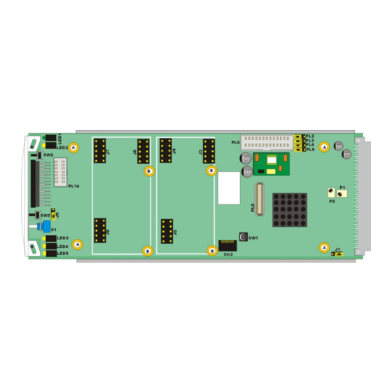
Crystal Vision Hardware installation 2 Hardware installation 2.1 Board configuration TANDEM 310 main board top-side Note : The potentiometers P1, P2, P3 and P4 have been factory set and should NOT be adjusted. Holes marked ‘A’ are for the fitting of the Dolby E decoder sub-board. -
Page 9: Input And Output Piggyback Boards
Crystal Vision Hardware installation 2.2 Input and output piggyback boards The main TANDEM 310 board has two positions where one of three types of I/O module can be plugged to enable analogue or digital input and output. The three types of piggybacks are 3G-AIP2, 3G-AOP2 and DIOP4. The following... -
Page 10: Aop2 Analogue Output
Crystal Vision Hardware installation 3G-AIP2 Channel number Link number Table showing links controlling the input gain of the 3G-AIP2 channels 3G-AOP2 Analogue Output This analogue piggyback has four balanced audio outputs. The links PL1-4 set 0dBFS to +18dBu (to the right, towards SK2/3) or +24dBu (to the left, towards SK1). -
Page 11: Fitting The I/O Piggybacks Onto The Main Board
Crystal Vision Hardware installation Fitting the I/O piggybacks onto the main board Example showing 3G-AIP2 and 3G-AOP2 piggybacks fitted The I/O piggybacks plug onto the main board such that main board plugs J3, J4, J5 and J6, J7, J8 align with piggyback sockets SK2, SK3, SK1. With the component side of the module top-most, align the piggyback sockets carefully with the plugs and push firmly. -
Page 12: Rear Modules And Signal I/O
Crystal Vision Rear modules and signal I/O 3 Rear modules and signal I/O The 2U Indigo 2 frames will house up to 12 single height modules and dual power supplies. The 1U Indigo 1 frames will house six single height modules and a single or dual power supply. - Page 13 Crystal Vision Rear modules and signal I/O Module Pin-out position Analogue audio 1/ AES1 Analogue audio 2/ AES2 Front Analogue audio 3/ AES3 Analogue audio 4/ AES4 Analogue audio 5/ AES5 Analogue audio 6/ AES6 Rear Analogue audio 7/ AES7...
-
Page 14: Rear Module Connections With Rm60
Crystal Vision Rear modules and signal I/O 3.2 Rear module connections with RM60 The RM60 being a single height module will allow maximum packing density with the option of an optical connection. Eight AES stereo pairs or eight mono analogue channels are presented as balanced I/O on the 26-way high density D-Type connector. - Page 15 Crystal Vision Rear modules and signal I/O Module Pin-out position Analogue audio 1/ AES1 Analogue audio 2/ AES2 Front Analogue audio 3/ AES3 Analogue audio 4/ AES4 Analogue audio 5/ AES5 Analogue audio 6/ AES6 Rear Analogue audio 7/ AES7...
-
Page 16: Rear Module Connections With Rm61
Crystal Vision Rear modules and signal I/O 3.3 Rear module connections with RM61 The RM61 is a dual height module presenting the eight channels of unbalanced audio AES stereo pairs on 75 ohm BNC connectors. The DIOP4 I/O module(s) must be used with this rear module as there is no provision for analogue audio I/O. -
Page 17: Rear Module Connections With Rm70
Crystal Vision Rear modules and signal I/O 3.4 Rear module connections with RM70 The RM70 being a dual height module will allow maximum packing density with the option of a dual optical connection. Eight AES stereo pairs or eight mono analogue channels are presented as balanced I/O on the 26-way high density D-Type connector. -
Page 18: 26-Way D-Type Audio Connections
Crystal Vision Rear modules and signal I/O 26-way D-Type Audio connections Module Pin-out position Analogue audio 1/ AES1 Analogue audio 2/ AES2 Front Analogue audio 3/ AES3 Analogue audio 4/ AES4 Analogue audio 5/ AES5 Analogue audio 6/ AES6 Rear... -
Page 19: Rear Module Connections With Rm74
Crystal Vision Rear modules and signal I/O 3.5 Rear module connections with RM74 The RM74 is a dual height module presenting the eight unbalanced AES stereo pairs on 75 ohm BNC connectors. The DIOP4 I/O piggyback(s) must be used with this rear module as there is no provision for analogue audio I/O. -
Page 20: General Purpose Interface
Crystal Vision General Purpose Interface 4 General Purpose Interface 4.1 Introduction Each frame slot has up to six connections ‘a-f’ for GPI control and monitoring. These connections are available at the rear of the frame on the 26-way D-Type remote connectors. - Page 21 Crystal Vision General Purpose Interface Bit 8 Bit 4 Bit 2 Bit 1 Preset Binary coding of GPI inputs to recall preset configurations in level mode Bit 8 Bit 4 Bit 2 Bit 1 Preset No change Not accessible in pulse mode.
-
Page 22: Alarms
Crystal Vision General Purpose Interface Alarms GPI outputs 5 and 6 (e, f) can be configured to be asserted (logic ‘L’) for a selection of error conditions. There are a number of alarm conditions which can be assigned to either or both of the GPI outputs. -
Page 23: Frame Gpi Connections
Crystal Vision General Purpose Interface 2U frame GPI connections GPI lines ‘a’ to ‘f’ of each card connect to two of four rear remote connectors as follows: Slot no. ‘a’ pin ‘b’ pin ‘c’ pin ‘d’ pin ‘e’ pin ‘f’ pin... -
Page 24: Indigo Dt Desk Top Box Gpi Connections
Crystal Vision General Purpose Interface Indigo DT desk top box GPI connections GPI lines ‘a’ to ‘f’ of each card connect to two rear remote connectors as follows: Slot no. ‘a’ pin ‘b’ pin ‘c’ pin ‘d’ pin ‘e’ pin ‘f’... -
Page 25: Control And Status Monitoring
Crystal Vision Control and Status monitoring 5 Control and Status monitoring TANDEM 310 controls and status can be accessed most easily by ‘VisionWeb’ remote control web browser software but also by card edge control and the rack front panel. TANDEM 310 is aware of what optional boards are fitted and adjusts the card edge/front panel menu tree accordingly to reflect the options available. -
Page 26: Reading Card Edge Leds
Crystal Vision Control and Status monitoring Reading card edge LEDs Card edge LEDs may be used in conjunction with status information from any connected remote status panel display or from VisionWeb if available. Refer also to the troubleshooting chapter for more help with solving problems and monitoring status information. -
Page 27: Using The Front Control Panel
Crystal Vision Control and Status monitoring 5.2 Using the front control panel At power up, the LEDs of all eight control panel keys will illuminate briefly. Once the panel has completed its power up and configuration sequence the panel will enter its status mode and display the current software version and frame IP address. -
Page 28: Control Panel Keys Overview
Crystal Vision Control and Status monitoring The TANDEM 310 home menu Rotate the shaft control to scroll through the menu structure and press ENTER to select the sub-menus. Press HOME at any time to return to the home menu. TANDEM 310 Video Status sub-menu Press ENTER to select the Video Status menu or SCROLL to display other sub- menus. -
Page 29: Menu Structure
Crystal Vision Control and Status monitoring Menu Structure The basic menu tree for both card-edge, front panel access and VisionWeb is identical and consists of the following menus and sub-menus. Note that some of these menus will change according to the optional boards fitted – for example references to AES will only appear if a DIOP4 piggyback is fitted. - Page 30 Crystal Vision Control and Status monitoring Chroma Gain U Lift U Gain V Lift V Gain Calibrate & Gain Cal Lift & Gain Vanc & Dolby E Sequence Vanc Blank Vanc Blank Dolby Frame Sequence ATC Input Present Lock to ATC...
- Page 31 Crystal Vision Control and Status monitoring DeEmbedder Delay User & Frame Present Frame Delay User Delay Discrete Delay User & Frame Present Frame Delay User Delay Delay Value User Delay PCM Audio (-20 to+400mS) AES I/O Configure Front Input Termination...
- Page 32 Crystal Vision Control and Status monitoring Store Recall GPI Preset /Recall GPI Enable GPI Level (high/low) GPI Trigger (level/pulse) Resets Board Reset Factory Reset exc. Presets Factory Reset inc. Presets GPO5 Alarms Status Asserted Video Video Missing Video Black Video Frozen...
-
Page 33: Controlling Cards Via Visionweb
Control and Status monitoring 5.3 Controlling cards via VisionWeb Crystal Vision cards use an XML file to create a control database that is used by the card’s front-edge controller, the Indigo frame front panel controller and the VisionWeb software. VisionWeb software offers a full range of controls with slider controls etc. -
Page 34: Control Descriptions
The controls of TANDEM 310 are accessible from the front panel, the board edge or from Crystal Vision’s VisionWeb software. The description of controls used in this manual is based on VisionWeb GUI screen grabs but the path to locate controls via the front panel or board edge follows the same logic. -
Page 35: Status Menu
Crystal Vision Control Descriptions 6.1 Status Menu Video Status Display presence, standard and status of incoming video signal. Input Present On when input video is present. Displays video standard of incoming video i.e. 1080i 50, Input Standard 1080p 50, 720p 50, 625, 525 etc. -
Page 36: Sub Pcb Status
Crystal Vision Control Descriptions Sub Pcb Status Displays type of piggyback. Displays type of piggyback in front position (nearest handle) i.e. Front DIOP4, 3G-AIP2, 3G-AOP2 or none. Displays type of piggyback in rear position (nearest edge connector) Rear i.e. DIOP4, 3G-AIP2, 3G-AOP2 or none. -
Page 37: Rgb Proc-Amp
Crystal Vision Control Descriptions RGB Proc-amp Apply varying amounts of lift and gain to the Red, Green and Blue channels of the video path. Apply a positive or negative DC offset to the black level of Red/Green/Blue Lift the Red, Green and Blue components of the video path. -
Page 38: Vanc & Dolby E Sequence
Crystal Vision Control Descriptions Return Lift and Gain for all components to their calibrated Cal Lift & Gain values of 0 lift and 100% gain. Vanc & Dolby E Sequence Blank ancillary data and lock progressive HD video output to ATC, or invert sequence to help ensure that Dolby E has its guardband correctly positioned. -
Page 39: Audio Settings Menu
Crystal Vision Control Descriptions 6.3 Audio Settings Menu DeEmbedder Settings Monitor de-embedder channel status, invert channels, detect Dolby E encoded channel pairs, mono and resample stereo pairs. Present On when embedded channel detected. Silent On if the audio channel is silent i.e. consistently below the set threshold. -
Page 40: Discrete Settings
Crystal Vision Control Descriptions Select to enable resampling of the selected stereo pair output from the de- embedder. Resampling is used to seamlessly match the timing of audio signals when the user-controlled delay is altered and is the default Resample condition. -
Page 41: Audio Gain
Crystal Vision Control Descriptions Audio Gain Change the gain of the audio inputs by +/- 18dB. In total there are 32 audio gain controls, one for each of the 16 channels of de-embedded audio and 16 channels of external audio.The gain controls Gain 1-4 will give ±... -
Page 42: Deembedder Delay
Crystal Vision Control Descriptions DeEmbedder Delay These controls in combination with the video delay controls (0-10 frames) can be used to delay the de-embedded audio with respect to the video and compensate for any small delay between the incoming video and audio signals, or when bypassed, delay the video with respect to the audio by up to ten frames. -
Page 43: Discrete Delay
Crystal Vision Control Descriptions Discrete Delay These controls in combination with the video delay controls (0-10 frames) can be used to delay the external audio with respect to the video and compensate for any small delay between the incoming video and audio signals, or when bypassed, delay the video with respect to the audio by up to ten frames. -
Page 44: Delay Value
Crystal Vision Control Descriptions Delay Value Set the ‘User Delay’ value for de-embedded and external audio signals. Set the delay value between -20 to +400mS for all channel pairs (de- PCM Audio (mS) embedded or discrete) with the ‘User Delay’ control selected. -
Page 45: Audio Router Menu
Crystal Vision Control Descriptions 6.4 Audio Router Menu Embedder Router Select the channels that will be embedded into the output video. The available channels for selection will depend on the optional piggyback and sub-boards fitted. The screen grab below shows a DIOP4 piggyback in the front and rear positions giving a potential of 16 external AES Inputs. -
Page 46: Aes Output Router
Crystal Vision Control Descriptions AES Output Router Select the channels that will be output as AES signals. This menu is only available if a DIOP4 piggyback is fitted. The number of AES output channels available for routing will depend on the number of DIOP4 piggybacks fitted. The screen grab below shows a single DIOP4 piggyback in the front position configured as all outputs. -
Page 47: Analog Output Router
Crystal Vision Control Descriptions Analog Output Router Select the channels that will be output as analogue audio. This menu is only available if a 3G-AOP2 piggyback is fitted. The screen grab below shows a 3G-AIP2 piggyback in the front position and a 3G-AOP2 in the rear. -
Page 48: Mute & Group Enable
Crystal Vision Control Descriptions Mute & Group Enable Mute embedder output and external AES and analogue outputs, enable embedder groups and select embedder encoding mode. The screen grab below shows a single DIOP4 piggyback fitted. Embed Mutes Select to mute embedder output channels. -
Page 49: Presets, Resets & Gpi/Os Menu
Crystal Vision Control Descriptions 6.5 Presets, Resets & GPI/Os Menu Presets Up to 16 user-defined configurations may be stored and recalled either from VisionWeb or through the use of external GPIs. Presets store the board setup data including operating mode card status. The presets are numbered 1-16. -
Page 50: Resets
Crystal Vision Control Descriptions Resets Reset the board to its default settings. Reset the board to default settings but leave preset memories Fact. Res Exc unaffected. Preset Fact. Res Inc Reset the board to default settings and erase preset memories. -
Page 51: Gpo5/Gpo6 Alarms
Crystal Vision Control Descriptions GPO5/GPO6 Alarms Set conditions to trigger GPO5/GPO6 alarms. Screen grab below is for GPO5 but GPO6 has identical options. Available alarms vary according to piggyback and sub-boards fitted. Asserted On when alarm is asserted (active). Video... - Page 52 Crystal Vision Control Descriptions Set to assert whenever an AES channel pair is missing, AES input silent for the period set by the ‘Silence Delay’ control or is missing/silent/Dolby E Dolby E encoded. A DIOP4 piggyback must be fitted. Analog Audio Silent (only...
-
Page 53: Specification
Crystal Vision Specification 7 Specification General Dimensions 100mm x 266mm module with DIN 41612 connector. Weight 200g. Power TANDEM 310 - 9 Watts. consumption FIP - 0.6 Watts. FOP - 0.6 Watts. FIO - 1 Watt. Inputs Video HD or SD SDI 270 Mb/s to 2.970 Gb/s serial digital compliant to EBU 3267-E, SMPTE 259, SMPTE 292-1 and SMPTE 424/425-A. - Page 54 Crystal Vision Specification RM60 One video output with 110 ohm balanced audio on a high density D- Type and SC optical I/O. RM61 Two video outputs with eight x 75 ohm unbalanced audio on BNCs and SC optical I/O. RM70 One video output with 110 ohm balanced audio on a high-density D- Type and SC optical I/O.
- Page 55 Crystal Vision Specification Input fail output Type: Dark Blue. Control Local: Intuitive board edge interface with two select buttons, shaft encoder and ten character alphanumeric display. Remote: Control from frame active front panel and remote panel. VisionWeb Control is available via the web server on the frame and allows operation using a standard web browser on a PC or tablet.
-
Page 56: Troubleshooting
Crystal Vision Troubleshooting 8 Troubleshooting Card edge monitoring The front edge of the card provides useful power rail monitoring and input status. TA DE G1 G3 Ncal SCROLL TANDEM 310 ENTER Lock G2 G4 GPO6 /ADJ TANDEM 310 front edge view Card edge controls for explanation of card edge LEDs. -
Page 57: Appendix
Dolby E decoding. Introduction The Crystal Vision Statesman PC control software is designed to control a range of Crystal Vision modules via Ethernet control from a PC. Statesman provides a user friendly means of configuring and operating Crystal Vision modules with the benefit of “see-at-a-glance”... -
Page 58: Control Descriptions
The controls of TANDEM 310 are accessible from the front panel, the board edge or from Crystal Vision’s Statesman software. The description of controls used in this manual is based on Statesman but the path to locate controls via the front panel or board edge follows the same logic. -
Page 59: Status
Crystal Vision Appendix 1 The board status is shown using a mixture of simulated LEDs and text information. As a general rule a green LED shows a good condition such as input present. An amber Status LED will give a warning as with video black or video frozen. If a LED turns red this is a fault condition. -
Page 60: Control
Crystal Vision Appendix 1 The control tab contains the TANDEM 310 configuration controls. Control Video Select to enable BNC as the input video source. Video Input Select Select to enable optical as the input video source. N.B. the optional SPF module Optical and correct rear module must be fitted. -
Page 61: Audio Input
Crystal Vision Appendix 1 The audio status and control tab is where the non-routing audio controls are located. In this menu, green LEDs are used to indicate audio present on the 16 Audio Input audio channels embedded in the incoming video. Further LEDs are used to indicate whether any of the 16 channels are silent or contain Dolby E. -
Page 62: Audio Delay
Crystal Vision Appendix 1 Each de-embedder, audio input and decoded Dolby E stereo pair has a set of controls to enable the various delays. These controls in combination with the video delay controls (0-10 frames) can be used to delay the audio with respect to the video and... -
Page 63: Audio Gain
Crystal Vision Appendix 1 In total there are 32 audio gain controls, one for each of the 16 channels of de-embedded audio and 16 channels of external audio (or six channels of external audio and ten channels of decoded Dolby E if decoder fitted). The Audio Gain gain controls will give ±... -
Page 64: Embedder Router
Crystal Vision Appendix 1 At the heart of TANDEM 310 is this 32 input/16 output routing matrix. The embedder router will allow any of the up to 32 possible inputs, 16 Embedder Router embedded channels and up to eight stereo external audio inputs or decoded Dolby E stereo pairs to be routed to any of the 16 embedded outputs. -
Page 65: Embedded Op Router
Crystal Vision Appendix 1 This 32 x 16 router is for routing signals to the optional audio De-embedded Op output modules. Any of the 16 de-embedded channels or 16 router external audio inputs can be routed to 16 external audio outputs. -
Page 66: Aes Output Router
Crystal Vision Appendix 1 This 32 x 16 router is for routing signals to the optional audio output modules. Any of the 16 de- embedded channels or 16 external audio inputs AES Output Router can be routed to 16 external audio outputs. This tab appears whenever a DIOP4 but no 3G-AOP2 piggyback is fitted. -
Page 67: Rgb Proc-Amp
Crystal Vision Appendix 1 The video proc-amp allows adjustment of the individual RGB lift RGB Proc-Amp and gain of the signal path. Red/Green/Blue Proc-Amps Modify the output video signal by altering the levels of the individual colour components in the RGB domain. -
Page 68: Yuv Proc-Amp
Crystal Vision Appendix 1 This video proc-amp allows adjustment of video gain, black level and independent YUV gains. The maximum increase in overall gain allowed YUV Proc-Amp is 200%, should any combination of controls be set where this maximum would be exceeded the gain will be limited to 200%. -
Page 69: Gpo
Crystal Vision Appendix 1 The GPO5 and GPO6 outputs are reserved for alarm indication and may each be assigned to any of the many video and audio alarm conditions. Video, input groups or Dolby encoding missing will assert an alarm immediately whereas the silence alarms can be assigned a delay timer to delay the time after which an alarm is asserted. -
Page 70: Presets And Reset
Crystal Vision Appendix 1 Up to 16 user-defined configurations may be stored and recalled either from Statesman or through the Presets and use of external GPIs. Presets store the board setup data including operating mode card status. The Reset presets are numbered 1-16. Reset the board to factory (default) settings. -
Page 71: Dolby E Decoder Controls
Crystal Vision Appendix 1 9.3 Dolby E decoder controls The optional Dolby E decoder board (DBE-D) decodes Dolby E signals embedded into the de-embedded input video signal or external AES inputs, and outputs five stereo pairs: A, B, C, D and DM (downmix). These outputs appear as inputs to the embedder and output routers. -
Page 72: Audio Delay
Crystal Vision Appendix 1 Extend Audio Delay tab features to Dolby E decoder Audio Delay outputs. Dolby Decoder Delay For the five channel pairs output from the Dolby E decoder board. Present On if the Dolby E decoded channel pair is present. -
Page 73: Audio Gain
Crystal Vision Appendix 1 Extend Audio Gain tab features to Dolby E decoder outputs. Audio Gain Channel Gain Select the group of four channels to apply the gain to. Note that the gain of dE D left channel will be set by fader Gain 3 and dE D right channel by Gain 4. The gains of dE A Select Channels left, dE A right, dE B left and dE B right are set by Gain 1, 2, 3, 4 respectively. -
Page 74: Embedder Router
Crystal Vision Appendix 1 Extend inputs to embedder router to include Embedder Router Dolby E decoder output channels. OP Chs Additionally select outputs from the Dolby E decoder to be embedded. Router Select ten Dolby E decoder output channel(s) as sources to the embedder router. N.B. -
Page 75: Aes Output Router
Crystal Vision Appendix 1 Extend the routable to include ten decoded Dolby E channels which can be routed to up AES Output Router to eight external digital audio outputs. AES Channels Route the 16 channels embedded in the input video, six optional input AES channels and ten Dolby E decoder channels to the eight optional AES outputs. -
Page 76: Dolby Decoder Router
Crystal Vision Appendix 1 Select any de-embedded signal or Dolby Decoder Router AES input as a source for the Dolby E decoder (DBE-D). Dolby Decode Source Route the 16 channels de-embedded from the input video or six optional input AES channels as sources for the Dolby E decoder board (DBE-D). -
Page 77: Gpo
Crystal Vision Appendix 1 For all possible AES inputs, select silence and Dolby E presence alarm conditions. Also select Dolby decoder output silence alarm conditions. GPO5/GPO6 Set the various conditions that assert GPO5 and GPO6. Set the conditions for the external AES input signals that assert the GPO.
Need help?
Do you have a question about the Indigo TANDEM 310 and is the answer not in the manual?
Questions and answers