
Subscribe to Our Youtube Channel
Related Manuals for Genius iTouch Series

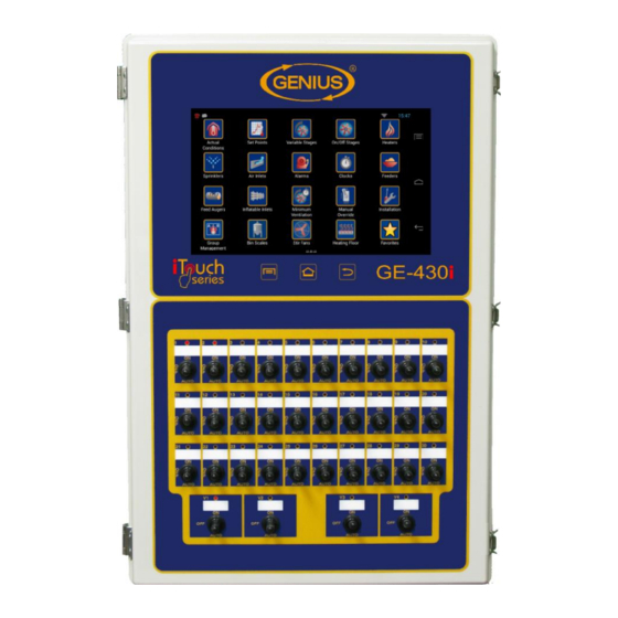
Summary of Contents for Genius iTouch Series
- Page 1 MULTIZONE VERSION Installation Guide For additional information, refer to the User Manual by following this link: www.farmquest.com/doc/UserGuide_iTouch.pdf...
-
Page 2: Warnings And Precautions
INSTALLATION GUIDE WARNINGS AND PRECAUTIONS Although the manufacturer has made every effort to ensure the accuracy of the information contained herein, this document is subject to change without notice due to ongoing product development. WARNINGS AND PRECAUTIONS Equipment, probe failure, blown fuses and/or tripped breakers may prove harmful to the contents of the building. - Page 3 INSTALLATION GUIDE WIRING DIAGRAM Page 3...
-
Page 4: Board Layout And Identification
INSTALLATION GUIDE Board Layout and Identification MASTER CONTROL (with variable outputs [ex. 430]) 8 INPUT BOARD POT BOARD X1200 X1205 ( JP 1) ( JP 2) P O T 1 P O T 2 P O T 3 P O T 4 P O T 5 P O T 6 P O T 7... - Page 5 INSTALLATION GUIDE SLAVE UNIT (with variable outputs [ex. SL430]) POT BOARD X1205 P O T 1 P O T 2 P O T 3 P O T 4 P O T 5 P O T 6 P O T 7 P O T 8 RELAY BOARD RELAY BOARD...
- Page 6 INSTALLATION GUIDE MASTER CONTROL (without variable outputs [ex. ST40]) 8 INPUT BOARD POT BOARD X1200 X1205 ( JP 1) ( JP 2) P O T 1 P O T 2 P O T 3 P O T 4 P O T 5 P O T 6 P O T 7 P O T 8...
- Page 7 INSTALLATION GUIDE SLAVE UNIT (without variable output [ex.: SLST40]) ** This board must be ordered separately. Page 7...
-
Page 8: Wiring Diagram Sensor & Comm. Board (X1199)
INSTALLATION GUIDE Wiring Diagram Sensor & Comm. Board (X1199) Page 8... -
Page 9: Wiring Diagram 8-Input Board (X1200)
INSTALLATION GUIDE Wiring Diagram 8-Input Board (X1200) Page 9... -
Page 10: Wiring Diagram Mgcb 8-Input Board (X1399)
INSTALLATION GUIDE Wiring Diagram MGCB 8-Input Board (X1399) Page 10... -
Page 11: Wiring Diagram 8 Comm. Port Board (X1276)
INSTALLATION GUIDE Wiring Diagram 8 Comm. Port Board (X1276) Page 11... -
Page 12: Wiring Diagram Output Board (X1201)
INSTALLATION GUIDE Wiring Diagram Output Board (X1201) Page 12... -
Page 13: Wiring Diagram Relay Board (Rel-5)
INSTALLATION GUIDE Wiring Diagram Relay Board (REL-5) Page 13... - Page 14 INSTALLATION GUIDE Page 14...
-
Page 15: Wiring Diagram Air Inlet
INSTALLATION GUIDE Wiring Diagram Air Inlet Page 15... -
Page 16: Wiring Diagram Variable Board (Var-2)
INSTALLATION GUIDE Wiring Diagram Variable Board (VAR-2) Page 16... -
Page 17: Wiring Diagram Slave Pot Board And Relay Control
INSTALLATION GUIDE Wiring Diagram Slave Pot Board and Relay Control Page 17... -
Page 18: Wiring Diagram Slave Relay Board (Rel-5)
INSTALLATION GUIDE Wiring Diagram Slave Relay Board (REL-5) Page 18... - Page 19 INSTALLATION GUIDE Page 19...
-
Page 20: Wiring Diagram Slave Variable Board (Var-2)
INSTALLATION GUIDE Wiring Diagram Slave Variable Board (VAR-2) Page 20... -
Page 21: Wiring Diagram V4
INSTALLATION GUIDE Wiring Diagram V4 Page 21... -
Page 22: Wiring Diagram Optigain-1
INSTALLATION GUIDE Wiring Diagram Optigain-1 Page 22... -
Page 23: Typical Installation Layout Fbt / Lim
INSTALLATION GUIDE Typical Installation Layout FBT / LIM Page 23... -
Page 24: Wiring Diagram Fbt / Lim
INSTALLATION GUIDE Wiring Diagram FBT / LIM Page 24... -
Page 25: Wiring Diagram Ms10
INSTALLATION GUIDE Wiring Diagram MS10 Page 25... -
Page 26: Typical Installation Layout Pig Sorters
INSTALLATION GUIDE Typical Installation Layout Pig Sorters Page 26... -
Page 27: Wiring Diagram Pig Sorter
INSTALLATION GUIDE Wiring Diagram Pig Sorter Page 27... -
Page 28: Pig Sorter Board
INSTALLATION GUIDE Pig Sorter Board Page 28... -
Page 29: Wiring Diagram Weather Station
INSTALLATION GUIDE Wiring Diagram Weather Station Page 29... -
Page 30: Wiring Diagram Batch Loader
INSTALLATION GUIDE Wiring Diagram Batch Loader Page 30... -
Page 31: Wiring Diagram V4/M & V2/M
INSTALLATION GUIDE Wiring Diagram V4/M & V2/M Page 31... -
Page 32: Floor Scale Board
INSTALLATION GUIDE Floor Scale Board Page 32... -
Page 33: Wiring Diagram Floor Scale
INSTALLATION GUIDE Wiring Diagram Floor Scale Page 33... -
Page 34: Wiring Diagram V2/Led
INSTALLATION GUIDE Wiring diagram V2/LED Page 34... -
Page 35: Wiring Diagram Cdc-4
INSTALLATION GUIDE Wiring diagram CDC-4 Page 35... -
Page 36: Wiring Diagram Mbus
INSTALLATION GUIDE Wiring diagram MBUS Page 36... -
Page 37: Electrician's Notes
INSTALLATION GUIDE ELECTRICIAN’S NOTES (PROBE WIRING) SHIELDED WIRE AWG #22 WITH 16/30 STRANDING, 500ft (150m) MAXIMUM LENGTH (Ex.: DECA 73-310). For other probe, refer to specific probe manual for appropriate maximum length and wire size or use AWG #22, 500ft (150m) MAXIMUM LENGTH. (COMMUNICATION WIRING) SHIELDED, TWISTED PAIR (8 TWIST/FT). - Page 38 INSTALLATION GUIDE JP1 - JUMPER MUST BE INSTALLED ON PIN 2-3 = 4-20mA AND JP2 - JUMPER MUST BE INSTALLED ON PIN 1-2 = STANDARD IF A STATIC PRESSURE PROBE IS USED, JUMPER JP1 MUST BE SET TO POSITION 2-3 (4-20mA). OTHERWISE, JUMPER JP1 MUST BE INSTALLED IN POSITION 1-2 (STANDARD).
- Page 39 INSTALLATION GUIDE INSTALLATION Page 39...
-
Page 40: Unpacking
INSTALLATION GUIDE This section will inform the electrician on proper wiring and installation procedures for the controller. The manufacturer recommends that the following installation instructions be followed to as closely as possible, and that all work be performed by a certified electrician. Failure to do so may void the warranty. -
Page 41: General Installation Guidelines
INSTALLATION GUIDE General installation guidelines Controller It is recommended to install the unit in a hallway to limit the controller exposure to noxious gases. In order to avoid condensation problems inside the controller, it is recommended to install the controller on an inside wall. If it is not possible, use spacers to have an air gap between the wall and the controller. -
Page 42: Mounting
INSTALLATION GUIDE It is also strongly recommended to install a backup thermostat system parallel to the controller module output (see figures 9 and 10) to supply sufficient airflow and heating. The backup system and alarm must be thoroughly tested and verified as working properly before using the ventilation system. -
Page 43: Connection Procedure
INSTALLATION GUIDE Connection procedure Detailed wiring diagrams Typical Sensor Wiring for Temperature Probes An inside temperature sensor should be located in the area which gives the most accurate temperature reading to achieve optimum ventilation. The sensor should be connected to the controller with a shielded two-wire cable. -
Page 44: Typical Feed Sensor Wiring
INSTALLATION GUIDE Typical Feed Sensor Wiring Feed sensors (ex.: CSD-1 Current Switch Detector) should be mounted inside the controller enclosure with the feeder power wire running through the sensor loop. If a single sensor monitors multiple feeder circuit, run the wires from all feeder groups the same direction through the sensor loop. -
Page 45: Typical Variable Stage Wiring
INSTALLATION GUIDE Typical Variable Stage Wiring FIGURE NO. 4 Typical Variable Stage Wiring VAR. BOARD X1204 LINE OUT 1 115/230 OUT 2 VA R L2/N FIGURE NO. 5 Other Variable Stage Wiring VAR. BOARD X1204 LINE OUT 1 115/230 OUT 2 VA R L2/N L2/N... -
Page 46: Typical Actuator Wiring
INSTALLATION GUIDE Typical Actuator Wiring Follow the calibration procedure in the user guide; otherwise the actuator positioning will be erratic. FIGURE NO. 6 Typical 115 VAC-Actuator Wiring POT BOARD RELAY BOARD X1205 X1184 P O T 1 P O T 2 P O T 3 P O T 4 NO C... -
Page 47: Typical Power Backup Wiring
INSTALLATION GUIDE Typical Power Backup Wiring A backup relay (DPDT) is connected to the power source 1 in normal operation but will switch to the power source 2 if source 1 is disabled. The backup relay should be selected to ensure it is able to support the required power load. FIGURE NO. -
Page 48: Typical Backup Thermostat Wiring
INSTALLATION GUIDE Typical Backup Thermostat Wiring If the controller or a module fails, the backup thermostats will activate the dedicated fan or heater as soon as temperature reaches the set point of the thermostat. The thermostat must be accessible for adjustment and must be set at 3 to 5 degrees above the fan’s set point or 3 to 5 degrees under the heater set point. -
Page 49: Typical V1 Or V2 Module Wiring
INSTALLATION GUIDE Typical V1 or V2 Module Wiring Those modules are used to add one or two variable outputs. The added outputs will follow the existing variable outputs of the VAR BOARD (X1204 or X1418). FIGURE NO. 11 Typical V1 and V2 Module Wiring X1243 VAR. -
Page 50: Typical Alarm Connection Wiring
INSTALLATION GUIDE Typical Alarm Connection Wiring The controller provides a normally open and normally closed dry contact to set off an alarm in case low or high temperature condition occurs. Moreover, this same contact can be used to signal a power failure or other malfunctions. It may be connected to an alarm system or directly to a siren and/or auto-dialer. -
Page 51: Powering Up Procedure
INSTALLATION GUIDE Powering up procedure Once the controller is properly mounted on the wall and all modules and sensors are connected to the terminal block, perform the following steps: Verify all connections Seal all cable entry holes. Hermetically close the controller Close the front panel and the lower access cover. -
Page 52: Specifications
INSTALLATION GUIDE Specifications CONTROLLER Storage temperature -20°C to 55°C (-4°F to 131°F) Operating temperature 0°C to 50°C (32°F to 122°F) Humidity 90% maximum Non-condensing NORMS CSA (NRTL/C) Weight (Small Enclosure) 12.4 kg (27.2 lb) Size (Small Enclosure) 50cm x 40cm x 20cm (19.7in x 15.8in x 7.9in) Weight (Large Enclosure) 13.3 kg (29.2 lb) - Page 53 INSTALLATION GUIDE RELAY BOARD (X1184 or X1414) OUTPUT RELAYS Maximum Power 20A @ 240VAC Maximum Current 2HP @ 240VAC, 1HP @ 120VAC Caution Notice These relays are rated by UL and CSA at 20A or 2HP. However, for outputs requiring frequent activation (ex : minimum ventilation fans working on a timer) it is recommended not to use more than 1 HP per relay (at 250...
- Page 54 INSTALLATION GUIDE 8 COMM. PORT (X1276) COMMUNICATIONS PORT (P9-P16) Maximum wire length (2400 bps) 820 feet (250m) Maximum wire length (19200 bps) 6.5 feet (2m) Recommended wire 2 strands, twisted pair, low capacity, shielded, AWG #22 SOURCE 12 VDC (12VDC) Maximum current allowed 100mA 8-INPUT MGCB BOARD (X1399)
- Page 55 INSTALLATION GUIDE INDEX / WARRANTY Page 55...
-
Page 56: Table Of Contents
INSTALLATION GUIDE TABLE OF CONTENTS WARNINGS AND PRECAUTIONS ................. 2 Board Layout and Identification ..................4 Wiring Diagram Sensor & Comm. Board (X1199) ............8 Wiring Diagram 8-Input Board (X1200) ................9 Wiring Diagram MGCB 8-Input Board (X1399) ............. 10 Wiring Diagram 8 Comm. - Page 57 INSTALLATION GUIDE Typical V1 or V2 Module Wiring ......................49 Typical Alarm Connection Wiring ....................... 50 Powering up procedure ..................... 51 Verify all connections ........................ 51 Hermetically close the controller ....................51 Put the power on ........................51 Secure the front panel with a lock ..................... 51 Specifications ........................
-
Page 58: Limited Warranty
INSTALLATION GUIDE LIMITED WARRANTY The manufactured equipment and supplied components have gone through rigorous inspection to assure optimal quality of product and reliability. Individual controls are factory tested under load, however the possibility of equipment failure and/or malfunction may still exist. For service, contact your local retailer or supplier. - Page 59 VER: 1.3 January 7, 2020...
Need help?
Do you have a question about the iTouch Series and is the answer not in the manual?
Questions and answers