Table of Contents
Advertisement
Quick Links
Advertisement
Table of Contents

Related Manuals for ritm Voyager 2N


Summary of Contents for ritm Voyager 2N
- Page 1 GPS/GLONASS tracker Voyager 2N Operating Manual. Rev. 1.3 St Petersburg, 2017...
-
Page 2: Table Of Contents
Operating Manual. Voyager 2N Table of Contents Introduction Device Overview Designation and Principle of Operation Specifications ATOL, ARI, 3G and Wi-Fi Versions of Voyager 2N LIGHT and LIGHT RS-485 Versions of Voyager 2N Design Voyager 2N Voyager 2N Wi-Fi Voyager 2N ARI... - Page 3 Operating Manual. Voyager 2N Accessing Configuration Software Configuration over USB Cable Configuration over CSD Configuration via GEO.RITM Configuration via RITM-Link Setup utility Device Details Date and Time Operation Modes SMS-messages Track A-GPS Sensors Counters Input terminals Output terminals Indication Communication channels...
- Page 4 Operating Manual. Voyager 2N Service Adding to GEO.RITM Tracker Installation on Vehicle Connections Marking and Connection of Connectors 20-Pin Connector Pinout Power supply connection Discrete Input Connection Digital Fuel Gauge Unit Connection Omnicomm LLS-AF20160 EPSILON ES4 Frequency Analog Fuel Gauge Unit Connection...
-
Page 5: Introduction
Operating Manual. Voyager 2N Introduction This operating manual covers Voyager 2N tracker (hereinafter referred to as the tracker) designed for monitoring of mobile objects and supporting connection of external devices for fuel level monitoring, connection to on-board computer, monitoring of operation of mechanisms and alarm system installed on the vehicle.1... -
Page 6: Device Overview
Operating Manual. Voyager 2N Device Overview Designation and Principle of Operation Voyager 2N is a small form-factor device for monitoring of mobile objects powered from a built-in battery and supporting connection of an external power source with 12/24 V rated voltage. - Page 7 The Voyager 2N 3G has all the features of the Voyager 2N version and is capable of transmitting and receiving data over 3G networks. The Voyager 2N Wi-Fi has all the features of the Voyager 2N version, while also being capable of transmitting and receiving data over IEE 802.11...
-
Page 8: Specifications
Operating Manual. Voyager 2N Specifications ATOL, ARI, 3G and Wi-Fi Versions of Voyager 2N GLONASS Communication channels CSD, GPRS in the GSM network GSM antenna External GPS/GLONASS antenna External EGTS protocol data transfer 3G network data exchange Yes (Voyager 2N 3G version) -
Page 9: Light And Light Rs-485 Versions Of Voyager 2N
Yes (excluding ATOL Version) 20×80×110 Dimensions, mm (23×80×108 for ATOL Version) Weight, g Operating temperature range, °С -40...+85 LIGHT and LIGHT RS-485 Versions of Voyager 2N GLONASS Communication channels CSD, GPRS in the GSM network GSM antenna Built-in GPS/GLONASS antenna... -
Page 10: Design
Operating Manual. Voyager 2N Design The tracker is made in a plastic enclosure. Different tracker versions have their unique design features. Voyager 2N www.ritm.ru 10 of 173... - Page 11 Operating Manual. Voyager 2N Part Designation When the battery compartment cover is opened, Tamper button device operating indicators turn on. When the cover is closed, the indicators are turn off. USB connector For configuration cable connection. 20-pin connector For connection of power supply and peripherals.
-
Page 12: Voyager 2N Wi-Fi
Operating Manual. Voyager 2N Voyager 2N Wi-Fi www.ritm.ru 12 of 173... - Page 13 Operating Manual. Voyager 2N SIM card 1 box SIM card 2 box Tamper button Battery installation location Part Designation When the battery compartment cover is opened, Tamper button device operating indicators turn on. When the cover is closed, the indicators turn off.
-
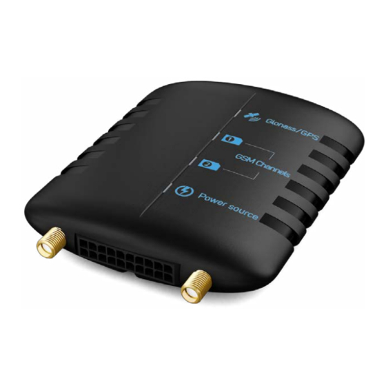
Page 14: Voyager 2N Ari
Operating Manual. Voyager 2N Voyager 2N ARI USB connector Connector for audio actuation device GPS/GLONASS signal reception indicator SIM card 1 operation indicator SIM card 2 operation indicator Power indicator Connector for GPS/GLONASS GSM antenna antenna connector 20-pin connector www.ritm.ru... - Page 15 Operating Manual. Voyager 2N microSD memory card box SIM card 1 box SIM card 2 box Tamper button Battery installation location Part Designation When the battery compartment cover is opened, Tamper button device operating indicators turn on. When the cover is closed, the indicators are turn off.
-
Page 16: Voyager 2N Atol
Operating Manual. Voyager 2N Voyager 2N ATOL Device status indicators RITM Voyager 2N-T SIM card connector Connector for GPS/ GSM antenna GLONASS antenna connector 20-pin connector microSD connector Tachograph connector www.ritm.ru 16 of 173... - Page 17 Operating Manual. Voyager 2N SIM card 1 operation SIM card 2 operation Power indicator indicator indicator GPS/GLONASS signal reception indicator RITM Voyager 2N-T Part Designation USB connector For configuration cable connection. 20-pin connector For connection of power supply and peripherals.
-
Page 18: Voyager 2N Light
Operating Manual. Voyager 2N Voyager 2N LIGHT USB connector “Test” indicator 20-pin connector www.ritm.ru 18 of 173... - Page 19 Operating Manual. Voyager 2N “Test” button SIM card box Part Designation Used for waking the tracker up from the sleep mode (turning “Test” button on the GPS receiver and the GSM modem), as well as for switching on/off the GPS receiver operation indicators.
- Page 20 Operating Manual. Voyager 2N Voyager 2N LIGHT RS-485 USB connector “Test” indicator 20-pin connector www.ritm.ru 20 of 173...
- Page 21 Operating Manual. Voyager 2N “Test” indicator SIM card box Battery connector Part Designation Used for waking the tracker up from the sleep mode (turning “Test” button on the GPS receiver and the GSM modem), as well as for switching on/off the GPS receiver operation indicators.
-
Page 22: Indication
Operating Manual. Voyager 2N Indication All tracker versions, but LIGHT, LIGHT CAN and LIGHT RS-485, have four indicators: 1. GPS/GLONASS reception indicator. 2. SIM card 1 reception indicator. 3. SIM card 2 reception indicator. 4. Power indicator. The device enters its work mode within a minute after power is supplied. -
Page 23: Sim Card Reception Indicators
Operating Manual. Voyager 2N SIM card reception indicators Indicator state Value SIM card 1 indicator ON SIM card 1 used SIM card 2 indicator ON SIM card 2 used GPS modem is either off or faulty Power indicator Indicator state... -
Page 24: Intended Use
Operating Manual. Voyager 2N Intended Use Operating Limits Operating conditions of the tracker should not exceed the allowed limits given in Section “Specifications”. Unpacking Tracker Prior to unpacking carefully inspect the package for visual signs of damage. After unpacking the device, visually verify the delivery package complies to the data sheet. -
Page 25: Getting Ready For Operation
Operating Manual. Voyager 2N Getting Ready for Operation Monitoring Server Data Data received during tracker operation are transferred to GEO.RITM monitoring software. Please clarify the following data with your monitoring service provider: IP-address and GEO.RITM monitoring server port. eu.ritm.ru is used by default. -
Page 26: Sim Card Insertion
Operating Manual. Voyager 2N SIM card Insertion Prior to inserting SIM card, please make sure of the following: • Tracker is powered off; • PIN code is disabled at each SIM card; • GPRS Internet service is enabled; • Call Routing is not enabled;... -
Page 27: Power On
To use ritm.conf configuration software, download it from the Ritm's official website. To use Ritm Configure application, install it in the Chrome Web Store. To connect using a Micro-USB cable, install the necessary drivers. To connect via a digital CSD-channel make sure the digital data transmission service (CSD) is enabled and the balance of the SIM card installed in the device is sufficient. -
Page 28: Tracker Operation
Operating Manual. Voyager 2N 2. Enter valid APN access point settings. 3. Enter details for the used GEO.RITM server. 4. Select the required operation mode and track record options. 5. If necessary, correct the history structure. 6. Use the indicators (see Section “Indication”) to verify the connection to satellites and registration in the mobile network. -
Page 29: Supported Devices And Interfaces
Details see in sections “CAN” and “Connection of IRMA MATRIX traffic sensors”. 8) An RS-485 is not provided in the LIGHT Version. 9) When using GEO.RITM cloud-based software, data can be displayed for only two fuel gauge units. 10) Not available in versions LIGHT and LIGHT RS-485. -
Page 30: Tracker Setup
Operating Manual. Voyager 2N Tracker Setup Accessing Configuration Software The device configuration software can be accessed both via GEO.RITM and RITM-Link cloud-based software and general purpose configuration software applications ritm.conf and Ritm Configure. Setup via cloud-based software is only possible in presence of an active GPRS connection with the device. - Page 31 Figure 1. Driver Check...
-
Page 32: Configuration Over Csd
Operating Manual. Voyager 2N Connect the tracker to your PC using a USB cable and run the configuration software. In the Connection Wizard, specify the connection type as USB/COM (Cable) and the COM port used by the tracker (Fig. 2). -
Page 33: Configuration Via Geo.ritm
The remote configuration via CSD is only possible from the engineering phone numbers. Configuration via GEO.RITM To access the configuration software via GEO.RITM cloud-based software, open the object card’s tab “Equipment” (Fig. 4). Below the tracker picture, click “Setup a device”. -
Page 34: Configuration Via Ritm-Link
Operating Manual. Voyager 2N Figure 4. Device configuration via GEO.RITM Configuration via RITM-Link To access the configuration software via RITM-Link cloud-based software, open the “Devices” section (Fig. 5). Use the pop-up menu to open the configuration software by clicking the “Setup” line. -
Page 35: Setup Utility
Operating Manual. Voyager 2N Setup utility The setup utility is used for defining and setting operation parameters of a tracker and data transfer channels. Upon specifying required options on the each page, click “Save changes” (Fig. 6). Otherwise, all specified settings will be reset. - Page 36 Operating Manual. Voyager 2N Figure 7. Configuration software’s Main page...
-
Page 37: Device Details
The SMS sending parameters, as well as transmitted alarm events are configured in the "SMS-messages" section. 11) IMEI is required for adding the tracker to the monitoring software GEO.RITM. IMEI is also listed in the data sheet. 12) The Tracking mode allows receiving object data more often than the Normal mode. - Page 38 Operating Manual. Voyager 2N Figure 8. “Device Details” section...
-
Page 39: Date And Time
Operating Manual. Voyager 2N Date and Time This section (Fig. 9) shows the date and time set in the tracker, as well as the date and time in the PC used for configuration. When the battery is removed, the tracker automatically resets the date and time settings. - Page 40 Operating Manual. Voyager 2N Figure 9. “Date and Time” section...
-
Page 41: Operation Modes
Operating Manual. Voyager 2N Operation Modes The operation modes (Fig. 10) define the conditions, in which a navigation receiver is turned on to seek coordinates or a GSM modem is turned on to transmit data from the tracker to a monitoring system server. - Page 42 Operating Manual. Voyager 2N “Online with power saving” mode The optimal mode for vehicle monitoring. Enables monitoring of a moving object/object with the running engine in a continuous and uninterrupted way. During parking, the tracker is off, has minimal energy consumption and its effect on the vehicle on-board battery are negligible.
- Page 43 Operating Manual. Voyager 2N Figure 10. “Operation Modes” section...
- Page 44 Operating Manual. Voyager 2N “Custom” mode This mode (Fig. 11) allows the user to manually select and setup individual conditions for turning on coordinate reception and submitting data to a monitoring system server. When the “Constant coordinate detection/Always connected to server” mode is selected, the tracker will operate the same as in the “Online”...
- Page 45 Operating Manual. Voyager 2N Figure 11. “Custom” operation mode...
-
Page 46: Sms-Messages
Operating Manual. Voyager 2N SMS-messages In this section (Fig. 12) the settings are configured the coordinates of the tracker according to a specified schedule, as well as alarm events, for sending to the user via SMS messages. General settings Configure the general settings for sending and displaying SMS: Device name Specify the name of the tracker. - Page 47 (the built-in battery in tracker); • Т - tracker CPU temperature. An example of SMS-message with the coordinates as text: Voyager 2N: 12:10:00 07-02-2017 N59.9563483 E030.4320933 12.1V/3.7V/45C 2. Yandex map/Google map/OSM – the coordinates will be given in the form of links to the map of Yandex/Google/OSM respectively.
- Page 48 SMS-messages. When you click through the "Restore default settings" link, it allows using the SMS in the factory default mode. An Example of SMS message with an alarm event: Voyager 2N: 12:09:27 07-02-2017 Incline www.ritm.ru 48 of 173...
- Page 49 Operating Manual. Voyager 2N Figure 12. SMS-messages...
-
Page 50: Track
Operating Manual. Voyager 2N Track The “Track” section (Fig. 13) allows setting conditions for storing route points in the tracker memory. The conditions for storing route points within the tracker memory are readings of the motion sensor, running engine sensor, schedule for storing points, mileage, and the maximum speed. - Page 51 Operating Manual. Voyager 2N Record coordinates at speed not exceeding a set threshold allows filtering out coordinates with the wrong speed. Record coordinates at 3D fixation allows for high-precision record of coordinates to the tracker memory and transfer of data to the server.
- Page 52 Operating Manual. Voyager 2N Figure 13. Track...
-
Page 53: A-Gps
Operating Manual. Voyager 2N A-GPS This section is intended to activate the Assisted GPS function (Fig. 14). In this case, the tracker receives additional data via GPRS, and the time required to determine the coordinates is reduced to tens of seconds. - Page 54 Operating Manual. Voyager 2N Figure 14. A-GPS...
-
Page 55: Sensors
Operating Manual. Voyager 2N Sensors The “Sensors” section (Fig. 15) allows configuration of parameters of motion, voltage, tilt, acceleration, crash, and temperature sensors. The tracker also takes into account the condition of sensors according to the selected operation mode and settings of track filters. - Page 56 Operating Manual. Voyager 2N Figure 15. Sensors...
- Page 57 Operating Manual. Voyager 2N Voltage sensor When this sensors is on and the voltage drops below the discharge threshold (below the set “blue” threshold), an alarm is activated, a distress event is generated and stored in the history, and a respective message is submitted to the server.
- Page 58 Operating Manual. Voyager 2N Figure 16. Voltage sensor...
- Page 59 Operating Manual. Voyager 2N Inclination sensor This section shows and enables adjustment of tilt sensor parameters. The following alarm messages can be received when the sensor is triggered: 1. “Tip” message: This message is generated at sensor inclination of over 45 degrees.
- Page 60 Operating Manual. Voyager 2N Figure 17. Inclination sensor...
- Page 61 Operating Manual. Voyager 2N Acceleration sensor For monitoring safety characteristics of the driving style, the device may generate an alarm event whenever an acceleration above the set threshold is detected. Set the value of 1 to 10 (m/s ), upon exceeding of which an “Acceleration”...
- Page 62 Operating Manual. Voyager 2N Figure 18. Acceleration sensor...
- Page 63 Operating Manual. Voyager 2N Crash sensor For monitoring of accidents and safety characteristics of the driving style (absence/presence of emergency braking), the device may generate “Failure” events. Specify the acceleration threshold for crashing or emergency braking of 0.1 to 24 g, upon exceeding of which a “Failure”...
- Page 64 Operating Manual. Voyager 2N Figure 19. Crash sensor...
- Page 65 Operating Manual. Voyager 2N Temperature sensor This section (Fig. 20) shows two real-time charts of the CPU temperature updated at different frequency: once in 5 seconds and once in 2 minutes. The current temperature of external sensor 1-Wire (if installed) is also shown.
- Page 66 Operating Manual. Voyager 2N Figure 20. Temperature sensor...
-
Page 67: Counters
Operating Manual. Voyager 2N Counters This section (Fig. 21) enables control and monitoring of the following built-in devices: • Odometer, which counts the overall mileage using GPS/GLONASS receiver data as source; • Machine hour counter, which uses built-in engine operation sensor data as source. - Page 68 Operating Manual. Voyager 2N Figure 21. “Counters” section...
-
Page 69: Input Terminals
Operating Manual. Voyager 2N Input terminals Discrete inputs Inputs 1 and 2 (Fig. 22) are discrete. You can either turn them off or set as “discrete”. After the input type has been selected, you can specify its designation: • Mechanism;... - Page 70 Operating Manual. Voyager 2N Figure 22. Discrete input...
- Page 71 Operating Manual. Voyager 2N Analog/frequency/pulse inputs Inputs 3 and 4 — universal. Specify the type of external signal to be supplied to these inputs: • Discrete; • Analog; • Frequency; • Pulse. Analog and frequency inputs are designed for connection and configuration of the fuel gauge unit.
- Page 72 Operating Manual. Voyager 2N Figure 23. Pulse input...
-
Page 73: Output Terminals
Operating Manual. Voyager 2N Output terminals The tracker has two open collector outputs for connection of actuation devices. Configure the output control mode (Direct/Inverse). To change an output’s current state, press the “Switch on/Switch off” hyperlink. “Speed mode violation alarm device”... - Page 74 Operating Manual. Voyager 2N Figure 24. “Output terminals” section...
-
Page 75: Indication
Operating Manual. Voyager 2N Indication The “Indication” section (Fig. 25) allows the user to select either of two available indicator operation modes on the tracker enclosure: “Standard” or “Constant”. Whenever the ”Standard” mode is chosen, indicators turn on for 30 minutes only after the battery compartment cover is taken off for diagnostics of tracker performance. - Page 76 Operating Manual. Voyager 2N Figure 25. “Indication” section...
-
Page 77: Communication Channels
Operating Manual. Voyager 2N Communication channels The “Communication channels” section (Fig. 26) allows the user to select a channel of data transferring. Establish connection Select communication channels which the tracker will use to transmit data: • Only through GPRS - use only GPRS for data transferring. - Page 78 Operating Manual. Voyager 2N Figure 26. “Communication channels” section...
-
Page 79: Coordinate Receipt Servers
The following values have to be specified: • Object number for connection to server (when not using GEO.RITM server); • Main coordinate receipt server IP address; • Password of the object to be connected to the server;... - Page 80 Operating Manual. Voyager 2N Figure 27. “Coordinate Receipt Servers” section...
- Page 81 Operating Manual. Voyager 2N Coordinate Receipt Servers in EGTS Protocol It's an open protocol, created for ERA-GLONASS system. If you want to learn more about this protocol, please follow the link http://www.nis-glonass.ru/en/. An object number is a unique tracker identifier in the mobile object monitoring system.
- Page 82 Operating Manual. Voyager 2N Figure 28. EGTS protocol server configuration 15) This example uses random EGTS servers and ports. Please clarify connection parameters with your service provider.
-
Page 83: Gprs Parameters
Operating Manual. Voyager 2N GPRS Parameters This section is used for setting parameters of connection to a GPRS access point (Fig. 29). If the “Auto detect APN settings” feature is enabled all connection options are set automatically depending on the communication service provider. - Page 84 Operating Manual. Voyager 2N Additionally section This section is used for storing access points, settings of which should be used for automatic detection. Enter parameters of available mobile networks in your region. Proper APN parameters can be requested from your mobile network operator.
- Page 85 Operating Manual. Voyager 2N Figure 29. "GPRS Parameters" section...
-
Page 86: Wi-Fi Parameters
Wi-Fi parameters The section is available only for the execution of the device with Wi-Fi. The version of Voyager 2N GLONASS Wi-Fi supports the transmission and reception of data on standard WLAN IEE 802.11 (Wi-Fi) and can act as: 1. A client. In this case, data from the tracker’s history is transferred to the server when connected to one of the saved wireless networks;... - Page 87 Operating Manual. Voyager 2N Figure 30. Module details...
- Page 88 Operating Manual. Voyager 2N Netwoks monitoring This page (Fig.31) shows all the currently available Wi-Fi network and identifies their main parameters: • SSID - broadcast network name; • MAC-address; • Security (No / WPA / WPA2); • Network signal strength; the level of signal attenuation.
- Page 89 Operating Manual. Voyager 2N Figure 31. Networks monitoring...
- Page 90 Operating Manual. Voyager 2N Connection to a network This page (Fig. 32) shows the current network to which the tracker is connected. You can manually specify the network to connect to. To do so, enter your name and password and click the Connect link.
- Page 91 Operating Manual. Voyager 2N Figure 32. Connection to a network...
- Page 92 3. IP-address – specify the access point IP-address with the default value - 192.168.4.1.4. 4. SSID – the broadcast network name. By default, the network is called Ritm<the last 8 digits of IMEI>. 5. Security (Open/WPA2). 6. Password - set a password to restrict the ability to connect to an access point.
- Page 93 Operating Manual. Voyager 2N Figure 33. Access point...
-
Page 94: Egts Parameters
Operating Manual. Voyager 2N EGTS Parameters This section (Fig. 34) is designed for users, who need to transfer data to third-party coordinate receipt servers over the EGTS protocol. EGTS is a data transfer protocol used for transmission of data from vehicles of Category M used for commercial passenger transfer and vehicles of Category N used for dangerous goods transfer. - Page 95 Operating Manual. Voyager 2N Use encryption in protocol Encryption of data upon transfer using the EGTS protocol: • Disabled - encryption is off; • GOST - data are encrypted according to the algorithm described in GOST 28147. Press “Additionally”, enter the encryption key and fill out the replacement table (if necessary);...
- Page 96 Operating Manual. Voyager 2N Figure 34. “EGTS parameters” section...
-
Page 97: Egts Statistics
Operating Manual. Voyager 2N EGTS statistics This section shows data transfer statistics for the EGTS protocol (Fig. 35). Any data transferred by the device over this protocol is shown. This section is used for reference and contains the following information: •... - Page 98 Operating Manual. Voyager 2N Figure 35. “EGTS statistics” section...
-
Page 99: Dispatch
Operating Manual. Voyager 2N Dispatch The “Dispatch” section (Fig. 36) is used to turn on a special dispatch unit connected to the tracker. When the dispatch unit is on, the system automatically answers any voice call from then engineering or any other number (if engineering numbers are not used and calling from any number is allowed). - Page 100 Operating Manual. Voyager 2N Figure 36. “Dispatch” section...
-
Page 101: Message Terminal
Operating Manual. Voyager 2N Message Terminal The “Message Terminal” (Fig. 37) allows the dispatcher to exchange messages with the tracker installed in the driver’s cabin. The driver would see incoming messages on the display of a touch screen connected to the tracker and installed in the vehicle cabin. - Page 102 Operating Manual. Voyager 2N Info messages Speed was reduced by 10% Speed was reduced by 20% Danger! Clear ice Dense fog, speed 5 kph Cancel speed reduction The ride is not discharged for delay When a message is created by a dispatcher, they need to enter a message (max.
- Page 103 Operating Manual. Voyager 2N Figure 37. “Message Terminal” section...
- Page 104 Operating Manual. Voyager 2N Touch Screen Operation Screen (Fig. 38) is designed for installation on vehicles and enables dispatching of rides. Connection of the screen to the tracker is done using an RS-232 serial port Colors and shades may differ from the original image depending on the hardware version of the screen.
- Page 105 Operating Manual. Voyager 2N • Confirmation of receipt of messages with confirmation request sent to the driver from the dispatch center; • Selection and transmission of a formalized message to be sent to the dispatch center. On-screen Name of touch-...
- Page 106 Operating Manual. Voyager 2N Submission of formalized messages from driver to dispatcher Formalized messages are stored to the screen’s non-volatile memory at the manufacturing plant. List of names of dispatcher’s formalized message groups: Code Message group Emergency call Leaving the line...
- Page 107 Operating Manual. Voyager 2N Messages to the dispatcher No remarks for road Ready to move Return to the fleet park Return to the fleet park, towing Work completed — early leaving Lunch time No shift turnaround Traffic delay Accumulation of foreign vehicles...
- Page 108 Operating Manual. Voyager 2N Using on-screen buttons, the driver selects a group of formalized messages, chooses a specific message within the group, and presses the confirmation button to sends it to the dispatcher. After the submission confirmation button has been pressed, the screen switches to its standby mode and shows the standby screen.
- Page 109 Operating Manual. Voyager 2N For on-screen display, text blinking can be used either for the complete message, or separately for each of its lines. The dispatch center can also send a delete command for the last formalized message received from a dispatcher.
-
Page 110: History Structure
Operating Manual. Voyager 2N History Structure The “History Structure” section (Fig. 39) enables selection of a list of parameters stored within the tracker and transmitted to the monitoring system server. For adding yet another parameter, the size of this parameter is automatically added to the overall size of the record in the field “One... - Page 111 Operating Manual. Voyager 2N Figure 39. "History structure" section...
-
Page 112: History
Operating Manual. Voyager 2N History The “History” section (Fig. 40) shows history of changes of parameters stored within the tracker memory. Parameters to be stored in the tracker memory may be chosen in the “History Structure” section. To configure record presentation parameters, press the gear button in the top right corner of the screen. - Page 113 Operating Manual. Voyager 2N Figure 40. "History" section...
-
Page 114: Engineering Numbers
Operating Manual. Voyager 2N Engineering Numbers This section (Fig. 41) is used to define a list of numbers, which allow to remotely connect to the tracker over a GSM/CSD channel for its reconfiguration. Numbers should be entered in either of the formats 8 ХХХ ХХХХХХХ or +7 ХХХ... - Page 115 Operating Manual. Voyager 2N Figure 41. “Engineering Numbers” section...
-
Page 116: Autoinformer
Operating Manual. Voyager 2N Autoinformer The version of Voyager 2N GLONASS ARIS supports the ability to play audio files stored on the MicroSD card that is installed in the tracker. This section (Fig.42) is used to play sound files on the card or local computer. - Page 117 Operating Manual. Voyager 2N Figure 42. “Autoinformer” section...
-
Page 118: Can
Operating Manual. Voyager 2N This section (Fig. 43) enables configuration of tracker-to-vehicle CAN bus connection and inputs configuration for connecting passenger traffic sensors MATRIX IRMA. CAN bus connection To work with CAN bus of the vehicle choose “Vehicles data transfer bus“... - Page 119 Operating Manual. Voyager 2N Figure 43. “CAN” section → Vehicles data transfer bus...
- Page 120 "Input terminals" section. In addition configure the triggering signal (positive or negative) in the "Input terminals" section, “Input signal polarity” option). 2. To transmit data into the GEO.RITM software activate transmission of data on states of required discrete inputs in the section "History Structure".
- Page 121 • Numbers of functional areas should be in consecutive order. When process of configuring and connecting sensors is complete you can create the Passenger traffic report (MATRIX sensor) in the GEO.RITM monitoring software. www.ritm.ru 121 of 173...
- Page 122 Operating Manual. Voyager 2N Figure 44. “CAN” section → Automatic Passenger Counting sensor IRMA MATRIX...
-
Page 123: I/O Ports
Operating Manual. Voyager 2N I/O Ports This section (Fig. 45) is used for assigning the RS232 and RS485 ports. Port Designation Application Not in use This port is not used Ritm-bin protocol Connection of Ritm-manufactured devices Strela D232 fuel sensor... - Page 124 Operating Manual. Voyager 2N Figure 45. “I/O Ports” section...
- Page 125 Operating Manual. Voyager 2N This section (Fig. 46) is used for showing the current tracker location on the map according to LBS data. Location detection by LBS may be used when the tracker is out of coverage of GPS/GLONASS satellites. For instance, in a building or covered parking.
- Page 126 Operating Manual. Voyager 2N Figure 46. “Map” section...
-
Page 127: Available Update
Operating Manual. Voyager 2N Available Update This section enables installation of available updates of the tracker software (Fig. 47). Install new versions of the software consistently. Before installing the latest update version download and install all previous versions. To update the tracker software, follow the steps below: 1. - Page 128 Operating Manual. Voyager 2N Figure 47. "Available Update" section...
-
Page 129: Service
Operating Manual. Voyager 2N Service The “Service” section is used for storing the applied configuration to a file and loading it from a file, setting the master code and the IMEI number submittal form (Fig. 48). When similar setup has to be applied to a large number of devices, the best practice would be to properly setup one device, store its configuration in a file, and then upload it to other devices from this file. - Page 130 Operating Manual. Voyager 2N “Forced reset of device” If the tracker has stopped working as expected, reset it. www.ritm.ru 130 of 173...
- Page 131 Operating Manual. Voyager 2N Figure 48. "Service" section...
-
Page 132: Adding To Geo.ritm
If you do not yet have a user account, perform the registration procedure by following the “Registration” hyperlink. Follow the wizard hints during the registration procedure. In case of questions, please refer to “GEO.RITM. User Manual" document. Enter your account. In the main menu select the “Mobile Objects” section. - Page 133 Operating Manual. Voyager 2N After add an object procedure is finished, the new object will appear in the “Mobile Objects” section of the main menu (Fig. 50). Figure 50. GEO.RITM Service www.ritm.ru 133 of 173...
-
Page 134: Tracker Installation On Vehicle
Operating Manual. Voyager 2N Tracker Installation on Vehicle To avoid cross interference, do not install the tracker nearby radio sets, recorders, and speaker systems. When installing on a vehicle, make sure the tracker is connected to 12/24 V on-board mains. Use wire with the cross section of at least 0.75 mm... - Page 135 Operating Manual. Voyager 2N From the perspective of coordinate reception, the most favorable conditions for installation of the antenna of a navigation receiver in the vehicle are under the plastic covering in the passenger compartment or nearby the windshield. When choosing the installation location, please...
-
Page 136: Connections
Operating Manual. Voyager 2N Connections Marking and Connection of Connectors Marking of connectors (Fig. 53) for connection of antennas and external devices is shown on the back side of the battery compartment cover. Figure 53. 20-pin tracker connector We recommend doing all connections with the tracker battery removed. -
Page 137: 20-Pin Connector Pinout
Operating Manual. Voyager 2N 20-Pin Connector Pinout Pin No. Designation Application Power positive terminal On-board mains connection Power negative terminal Intercom power supply positive terminal Intercom common terminal (GNDA) Connection of an intercom for two- Intercom microphone way control communications... -
Page 138: Power Supply Connection
Operating Manual. Voyager 2N Power supply connection Connect power with the power source disconnected and the battery removed! Connection of power (Fig. 54) should be done via pins 1 (power positive terminal) and 2 (power negative terminal) of the 20-pin connector. The connection should be done using a cable with the minimum cross-section of 0.75 mm... -
Page 139: Discrete Input Connection
Operating Manual. Voyager 2N Discrete Input Connection A signal from the security system, panic button, monitored mechanism sensor, or other monitored device can be connected to discrete or universal inputs (pins 9, 10, 11, 12). The input triggers immediately after the power negative terminal is shorted to power (grounded) and recovers upon opening. -
Page 140: Digital Fuel Gauge Unit Connection
Operating Manual. Voyager 2N Digital Fuel Gauge Unit Connection Omnicomm LLS-AF20160 The tracker may work with four digital fuel gauge units Omnicomm LLS-AF20160 (Fig. 56). The LLS-AF20160 fuel gauge unit is designed for measuring the fuel level and temperature in vehicle fuel tanks. - Page 141 Operating Manual. Voyager 2N 15 17 8 10 14 16 +12/24 V +12/24 Figure 57. Fuel gauge connection diagram www.ritm.ru 141 of 173...
- Page 142 Operating Manual. Voyager 2N 15 17 8 10 14 16 А А А А В В В В С С С С +12/24 V +12/24 V Figure 58. 2 fuel gauge connection diagram In the “I/O Ports” section, choose the designation “Omnicomm fuel gauge unit or equivalent model”...
- Page 143 Use the tracker configuration software to verify that data transfer from the connected gauge is added to the “History Structure” section. Enter your account in the GEO.RITM service. Open the “Connections” tab in the object card and specify gauges connected to the tracker (Gauge 1 and/or Gauge 2).
- Page 144 Operating Manual. Voyager 2N 4. Register gauge readings in the “History” section of the tracker configuration software. Register gauge readings only after the fuel level stabilizes! 5. Repeat Steps 3 and 4 the chosen number of calibration steps. 6. Fill out the calibration table with the values gathered (please see a filled example of the table in Figure 59).
- Page 145 Operating Manual. Voyager 2N Figure 60. EPSILON ES4 fuel gauge Connection of gauges is done via the RS-485 interface. Connect (Fig. 61) the yellow wire (RS-485 A) of the gauge connector to Pin 16 (RS-485 A) of the 20-pin tracker connector, and the green connector (RS-485 B) of the tracker connector to Pin 15 (RS-485 B) of the tracker.
- Page 146 Operating Manual. Voyager 2N 15 17 8 10 14 16 R = 240 Ohm EPSILON ES4 +12/24 V Figure 61. Fuel gauge connection diagram www.ritm.ru 146 of 173...
-
Page 147: Frequency Analog Fuel Gauge Unit Connection
Operating Manual. Voyager 2N Frequency Analog Fuel Gauge Unit Connection The tracker may work with frequency analog fuel gauge units Omnicomm LLS-AF20310. The LLS-AF20310 fuel gauge unit is designed for measuring the fuel level in vehicle fuel tanks and its transformation into an analog or frequency signal. - Page 148 Operating Manual. Voyager 2N 15 17 8 10 14 16 А А В В С С +12/24 V Figure 62. Frequency analog gauge connection diagram www.ritm.ru 148 of 173...
-
Page 149: Connection To Vehicle Can Bus
Operating Manual. Voyager 2N Connection to vehicle CAN bus Connect the tracker to the CAN bus of the vehicle to enable reception of on-board computer readings. To establish a connection, connect the CAN-L pin of the tracker with the corresponding CAN-L pin of the ODB2 connector, connect the CAN-H pin of the tracker with the corresponding CAN-H pin of the ODB2 connector of your vehicle (Fig. -
Page 150: Connection Of Irma Matrix Traffic Sensors
The tracker works with IRMA MATRIX passenger counting sensors. Received from the sensors information is stored in the tracker history and is transmitted to the monitoring software GEO.RITM. In the interface of the GEO.RITM you can build the appropriate report of the passenger traffic. - Page 151 Operating Manual. Voyager 2N ADC1 +24 V Door #2 limit switch DIN1 15 17 Door #3 limit switch 8 10 14 16 Door #1 limit switch ADC2 +24 V CAN-L CAN-H R = 120 Connector Connector Connector IRMA MATRIX sensor...
-
Page 152: Connection Of Dispatch Unit
Operating Manual. Voyager 2N Connection of dispatch unit To enable two-way voice communication with the dispatcher, the tracker may be used together with the dispatch unit (Fig. 65). Figure 65. Dispatch unit with PTT button To connect a dispatch unit to the tracker, use the special connector (supplied with the package). - Page 153 Operating Manual. Voyager 2N 15 17 8 10 14 16 PTT button Figure 66. Dispatch unit connection diagram www.ritm.ru 153 of 173...
-
Page 154: Temperature Sensor Connection
Operating Manual. Voyager 2N Temperature Sensor Connection Connection of a temperature sensor is done via the 1-Wire interface. Connect the power positive terminal of the temperature sensor to Pin 8 of the tracker. Connect the power negative terminal of the temperature sensor to Pin 2 of the tracker (Fig. -
Page 155: Touch Memory Reader Connection
Operating Manual. Voyager 2N Touch Memory Reader Connection Connection of a TM reader is done via the 1-Wire interface. Connect the power positive terminal of the reader to Pin 8 of the tracker. Connect the common power negative terminal of the reader to Pin 2 of the tracker (Fig. -
Page 156: Tracker Test Procedure
Operating Manual. Voyager 2N Tracker Test Procedure Never install a battery or connect external power before all connections are completed! Pressing and holding the tamper button for longer than 1 second switches the tracker to the test mode and restarts the navigation receiver in the “cold”... - Page 157 Operating Manual. Voyager 2N If the object has connected to the monitoring system and detected its location, the test is completed. If the object has not connected in the period exceeding 10 minutes: • Check the tracker power supply. In order to go online, 12/24 V external power supply has to be connected;...
-
Page 158: Maintenance
Operating Manual. Voyager 2N Maintenance At least twice per year visually inspect the tracker for enclosure or connector damage. At least once per month check the SIM card accounts for funds. www.ritm.ru 158 of 173... -
Page 159: Safety Precautions
Operating Manual. Voyager 2N Safety Precautions Properly operate the tracker and follow the safety precautions below: • Make sure the tracker is always dry, whether it is stored or in use. Ingress of liquid, rain, or other moisture, and operation under elevated humidity conditions may harm the electrical structure of the device;... -
Page 160: Transportation And Storage
Operating Manual. Voyager 2N Transportation and Storage The tracker should be transported in packaging in closed vehicles. Storage and transportation conditions should conform to those listed in class IE12 of EN 60721-3-1. Storage premises should be free of current- conducting dust, acid and alkaline fumes, corrosive gases and gases harmful to insulation. -
Page 161: Manufacturer's Warranties
Operating Manual. Voyager 2N Manufacturer’s Warranties The manufacturer guarantees that the tracker complies to requirements of the technical specifications, provided the client ensures compliances to conditions of transportation, storage, installation and operation. Warranty repairs of the tracker are done throughout the life cycle. The manufacturer’s warranty does not cover the battery. -
Page 162: Disposal Note
Operating Manual. Voyager 2N Disposal Note Batteries in the tracker package marked with the symbol (Fig. 69) should be disposed of separately from household waste. Figure 69. Symbol of separate disposal from household waste Used batteries may not be: • Disposed of together with household waste;... -
Page 163: Sms Commands
Operating Manual. Voyager 2N SMS commands Tracker is able to be configured by SMS. To set up the device, send SMS to the number of SIM card, which is in the device with text of command. At the same time: 1. -
Page 164: Json Commands
Operating Manual. Voyager 2N JSON commands Command Description Valid values Examples Set “Master- code” for access MASTER Four digits from 0 up to 9 {"Master":"1234"} or {"MASTER": "1234"} to the tracker settings REBOOT Restart device {"REBOOT":""} {"FOLLOW":"ON"} Enable/Disable ON - enable;... - Page 165 Operating Manual. Voyager 2N 1- Main RITM server; 2 - Reserve RITM server; Set up the 3 - Main EGTS server; SERVERx {"SERVER1":"dev1.eu.ritm.ru:9426","SERVER2":"dev2.eu.ritm.ru:9426"} server address 4 - Reserve EGTS server. Available to set up 2 servers the same time Object number...
-
Page 166: Text Protocol Commands
Operating Manual. Voyager 2N Text protocol commands Commands to request current tracker settings Command Description Syntax Example +CONNECT_SERVER=<N>,? where <N>: 1- Main RITM server; 2 - Reserve RITM server; 3 - Main EGTS server; Request of the current settings of... - Page 167 0 to 3, where: Request of the used data +PROTOCOL_TYPE +PROTOCOL_TYPE=1,? transferring protocol type 0-data transferring only in RITM protocol; 1- data transferring in RITM and EGTS protocols; 2- data transferring only in EGTS protocol; 3- data transferring is off.
- Page 168 Operating Manual. Voyager 2N +VR_FILTER_TRACK=1,? The response to the command is a SMS message in the following format: <Criterion>,<Time>, <Moving>,<Speed> where: Request of the current conditions <Criterion> - record coordinates: +VR_FILTER_TRACK for saving the route points in +VR_FILTER_TRACK=1,? 0 - always;...
- Page 169 Operating Manual. Voyager 2N +VER_INFO=1,? The response to the command is a SMS Request of the basic information +VER_INFO +VER_INFO=1,? message in the following format: about the tracker <"Device name">,<"Firmware version">, <"Version of memory chips"> +GET_IMEI=1,? +GET_IMEI Request of the IMEI...
-
Page 170: Commands To Change The Settings Of The Tracker
Specify the data transferring 0-data transferring only in RITM protocol; +PROTOCOL_TYPE +PROTOCOL_TYPE=1,0 protocol type 1- data transferring in RITM and EGTS protocols; 2- data transferring only in EGTS protocol; 3- data transferring is off. Changing of the current time +VR_PACK_SIZE=1,<The number of records>... - Page 171 Operating Manual. Voyager 2N +VR_FILTER_TRACK=1,<Criterion>, <Time>,<Moving>,<Speed> where: <Criterion> - record coordinates: Changing of the current 0 - always; conditions for saving the route 1 - only at motion; +VR_FILTER_TRACK=1,0, +VR_FILTER_TRACK points in the memory of the 2 - only at started engine;...
- Page 172 Operating Manual. Voyager 2N +GPRS_APN_AUTO=1,<The value> APN automatical configuration (equivalent to specifying where <The value>: +GPRS_APN_AUTO +GPRS_APN_AUTO=1,1 the options in section 0 - automatical configuration of APN is not used; "GPRS parameters") 1 - automatical configuration of APN is used.
- Page 173 Operating Manual. Voyager 2N Change history Revision Revision date Description 22.09.2016 Full revision of document The following sections were added: "A-GPS", 04.04.2017 "SMS-messages", "Communication channels", "Wi-Fi parameters", "Autoinformer" 05.06.2017 Appendix 1 was fixed Appendix 1 was fixed. Information about 26.12.2017 IRMA MATRIX sensors was added www.ritm.ru...
Need help?
Do you have a question about the Voyager 2N and is the answer not in the manual?
Questions and answers