
Related Manuals for ritm RIPR1


Summary of Contents for ritm RIPR1
- Page 1 Manual fire radio channel signaling device RIPR1 Data sheet Device identification number Firmware: QA specialist: Date of check: Signature:...
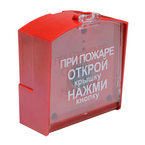
- Page 2 1. General Information The manual fire radio channel signaling device RIPR1 (hereinafter referred to as the device) is designed for operation with control panels “Contact” as a fire alarm device. When the button is pressed the device generates a fire alarm. Additionally the device generates and sends to the receiver the following messages: •...
- Page 3 4. Technical Specifications Specification Value Communication channels band, MHz 433.075 – 434.775 No. of communication channels Maximum distance for strong signal, up to 800 line-of-sight, m Transmitter radiated power, mW max 10 Monitoring period of signaling device operation in radio system, min Dimensions, mm 110×90×45 Weight, g...
- Page 4 5. Designation of Elements Fig. 5.1. Signaling device elements Element Designation JMP1, JMP2, JMP3 Jumpers for changing operating modes HL1, HL2 Visual indicators Tamper Fire alarm button contacts. When the button is pressed SW1, SW2 the contacts are open and the fire alarm is generated XP1, XP2 System connectors 3.6V (AA) battery holders.
- Page 5 JMP1 + JMP3 Hardware configuration reset mode Radio channel test mode / standalone JMP3 mode All jumpers removed Standby mode 7. Visual Indication Fig. 7.1. Standby m ode Alarm Normal state . . . Red, 2 sec period – fire alarm Period 60 seconds Red, 5 sec period –...
- Page 6 The battery is tested each time the sensor cover is closed! 3. Switch the RIPR1 to the mode of adding to a radio system (see Section 6). 4. Add the device to the radio system according to the manual of the unit the device is intended to work with.
- Page 7 The radio signal strength between the signaling device and the security and fire alarm panel is determined by the level of signal attenuation which can be viewed in the configuration software, page Radio Device Map, upon connection to the panel. 9.
- Page 8 9. Seal the enclosure at points indicated on positions 3, 4 (fig. 5.1.). Close the safety cover and seal the enclosure at the point indicated at the position 6 (fig. 5.1). 10. During construction works the installed signaling devices should be protected from mechanical damages and ingress of construction materials (whitewash, paints, cement kiln dust etc.).
Need help?
Do you have a question about the RIPR1 and is the answer not in the manual?
Questions and answers