Table of Contents
Advertisement
Quick Links
WARNING:
ALL phases of this installation must comply with NATIONAL, STATE AND LOCAL CODES
IMPORTANT — This Document is customer property and is to remain with this unit. Please return to service infor-
mation pack upon completion of work.
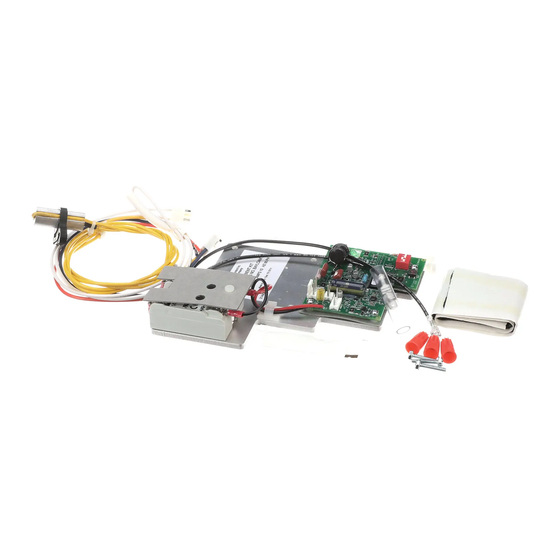
LOW AMBIENT KIT CONTENTS:
1 - Controller Module
1 - Liquid Line Temperature Sensor
1 - Outdoor Air Temperature Sensor
1 - B Y O Low Voltage Wiring Harness
1 - Sensor Clamp
1 - Thermal Grease
1 - Insulation Tape
1 - Information Label
3 - Screws, Wire Nuts, Wire Ties
1 - Installer's Guide.
INSPECTION:
Check carefully for any shipping damage. This must be
re ported to and claims made against the transportation
company immediately. Any missing parts should be re-
ported to your supplier at once and replaced with autho-
rized parts only.
INSTALLATION:
NOTE:
As the head pressure control is applied to units op-
erating in low ambient conditions, it is required that
the units have compressor crankcase heaters and
non-bleed txv's.Refer to the Low Ambient Applica-
tion documentation.
ATTACH INFORMATION LABEL
Attach the Information Label to the control box cover. This
l abel,identifiesfanmotorcyclingduringlowambientop-
eration.
MOUNTING CONTROL MODULE
1. Be certain power to unit is DISCONNECTED.
2. Remove cover panel on control box compartment.
3. Install control module into the control box.
a. If installing into an air conditioner only unit (non
heat pump), use the three (3) screws provided
and attach to the control box as illustrated in Fig-
ure 1.
b. If installing into a heat pump unit, remove the
three (3) screws holding the defrost board, place
low ambient kit assembly behind the defrost
board and reattach the defrost board and low am-
bient control with the three (3) screws provided in
the original defrost board mounting location. See
Figure 1.
Installer's Guide
Low Ambient Control Kit
BAYLOAM103
HAZARDOUS VOLTAGE - DISCONNECT POWER BEFORE SERVICING
18-HE46D1-3B-EN
①
MOUNTING CONTROL BOARD
COOLING ONLY AIR CONDITIONER
HEAT PUMP
HDPC-IN-18C
Advertisement
Table of Contents

Related Manuals for Trane BAYLOAM103


Summary of Contents for Trane BAYLOAM103
- Page 1 HDPC-IN-18C 18-HE46D1-3B-EN Installer’s Guide Low Ambient Control Kit BAYLOAM103 WARNING: HAZARDOUS VOLTAGE - DISCONNECT POWER BEFORE SERVICING ALL phases of this installation must comply with NATIONAL, STATE AND LOCAL CODES IMPORTANT — This Document is customer property and is to remain with this unit. Please return to service infor- mation pack upon completion of work.
- Page 2 Installer’s Guide MOUNTING LIQUID LINE TEMPERATURE SENSOR 2B. When completed, wrap the complete assem- 4. Remove the service access panel to the left side of bly with the insulation tape provided. the control box of the air conditioner or heat pump. 6.
- Page 3 Installer’s Guide MOUNTING OUTDOOR TEMPERATURE SENSOR ④ 7. Using pliers, bend the corner of the control box OUTDOOR TEMPERATURE SENSOR base downward, to create an opening for the sensor leads. See Figure 4. 8. Route the sensor, from the control board, down through the opening created in the control box base.
- Page 4 Installer’s Guide 9B) 200/230 Volt Heat Pump: See Figure 6 NOTE: Disconnect the black fan motor lead from the defrost To ease the insertion of the connector housing board relay (The black wire is attached to the “N.C.” on to the J5 header, place the connector on the terminal of the relay).
- Page 5 Installer’s Guide 9C) 460 Volt Heat Pump Models: See Figure 7 Connect the yellow lead wire to a 1/4" male tab on Disconnect the black fan motor lead from the fan the right hand side of the main contactor (low volt- relay (terminal #6).
- Page 6 Installer’s Guide SYSTEM SETUP Manual Mode (S2 dip switch 4 in “On” position) – The S2 dip switch 1, 2, 3 settings are read by the 10. The control board contains a momentary test switch controller and used to determine the liquid tempera- (S1) and a 4-position installer selectable dip switch ture set point when (S2).
- Page 7 Installer’s Guide ⑧ CONTROL BOARD B,Y,O LIQUID SENSOR LIQUID Lite AMBIENT AMBIENT Port SENSOR GREEN ALERT S2-1,2,3,4 DIP SWITCHES TEST TEST LEDS SYSTEM CHECK-OUT – COOLING UNITS ONLY Verify that the control module is installed and wired per The control board contains two LEDs; one green and the instructions contained within this installer’s guide.
- Page 8 About Trane and American Standard Heating and Air Conditioning Trane and American Standard create comfortable, energy efficient indoor environments for residential applications. For more information, please visit www.trane.com or www.americanstandardair.com The manufacturer has a policy of continuous data improvement and it reserves the right to change design and specifications with- out notice.
Need help?
Do you have a question about the BAYLOAM103 and is the answer not in the manual?
Questions and answers