
Related Manuals for Trane RTWB Helical-Rotary


Summary of Contents for Trane RTWB Helical-Rotary
- Page 1 Installation Operation Maintenance RTWB Helical-Rotary Chillers 200 to 700 kW Sizes 207-224 RTWB-SVN01B-E4...
- Page 2 Risk of damage to equipment. servicing. Trane assume no liability for W W A A R R N N I I N N G G installation or service procedures performed by unqualified personnel. Regulations on safety, construction, Risk for safety or health.
-
Page 3: Table Of Contents
Contents General Information Literature change history Unit inspection Inspection checklist Loose parts inventory Unit description Installation overview Installation – Mechanical Storage Location requirements Access restrictions Moving and rigging Lifting procedure Isolation pads Shipping items Unit leveling Water piping Water pressure-drop data Water treatment Water pressure gauges and thermometers Water pressure-relief valves... -
Page 4: General Information
General Information Literature change history An Owner Guide on the operation of the UCM-CLD chiller controls is This manual describes the available as a separate document. installation, operation, and maintenance of RTWB units. When the unit arrives, compare all nameplate data with ordering, submittal, and shipping information. -
Page 5: Unit Inspection
Trane sales office. • If concealed damage is discovered, stop unpacking the shipment. Do not remove the damaged material from the receiving location. Take photos of the damage, if possible. -
Page 6: Unit Description
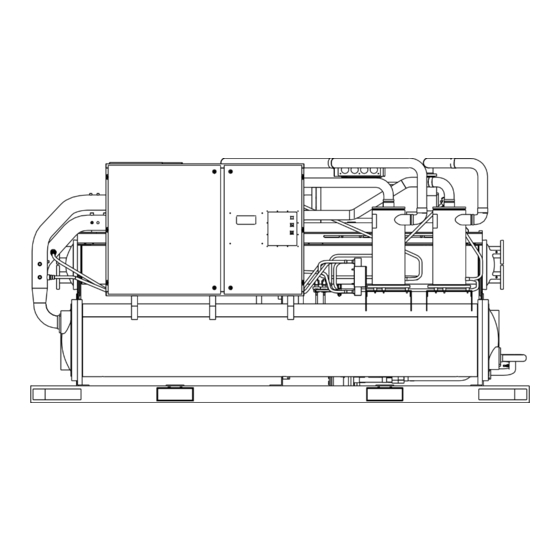
The chilled-water inlet and outlet openings are covered for shipment. The RTWB series features Trane's exclusive Adaptive Control ™ logic Figure 2 -– Component location for typical RTWB unit with Clear Language Display. - Page 7 General Information Where specified, supply and install Installation overview valves in the water piping upstream For convenience, Table 1 and downstream of the evaporator summarizes responsibilities that are and condenser water boxes to typically associated with the RTWB isolate the shells for maintenance chiller installation process.
- Page 8 General Information Table 1 – Installation overview Refer to the installation mechanical and electrical sections of this manual for detailed installation instructions. Requirement Trane supplied Trane supplied Field supplied Trane installed Field installed Field installed Rigging Safety chains Clevis connectors...
-
Page 9: Storage
Refer to Table 2 for unit operating weights. When in place, level the chiller within 6 mm over its length and width. The Trane Company is not responsible for equipment problems resulting from an improperly- designed or -constructed foundation. -
Page 10: Access Restrictions
Installation Mechanical Ventilation Access restrictions C C A A U U T T I I O O N N The unit produces heat even though Door clearances for the RTWB units the compressor is cooled by the are given in Figure 8. Refer to the To prevent unit damage, position refrigerant . -
Page 11: Isolation Pads
Installation Mechanical Dimensions in mm Size “A” 207 and 208 2880 210 to 224 4150 Figure 6 – Isolator pad location Provide shutoff valves in lines to the Isolation pads Evaporator water piping Figure 7 illustrates typical gauges, in order to isolate them The elastomeric pads shipped are evaporator piping components. -
Page 12: Water Piping
Installation Mechanical Manometer Evaporator Flow switch Balance valve Stop valves Air vent Expansion joints Thermometers Stop valves Filter Drainage Figure 7 – Suggested piping for typical RTWB evaporator Evaporator piping Leaving chilled-water piping • Air vents ( to bleed air from components system). -
Page 13: Water Piping
There are numerous methods to control condenser water temperature. Methods other than those shown can be employed to achieve the same results. Contact your local Trane office for details. Throttling valve This method maintains condensing pressure and temperature by throttling water flow leaving the... -
Page 14: Water Treatment
The Trane Company warranty specifically excludes liability for corrosion, erosion or deterioration of Trane equipment. Trane assumes no responsibility for the results of the use of untreated or improperly treated water, or saline or brackish water. -
Page 15: Water Pressure Gauges And Thermometers
Installation Mechanical Water pressure gauges and Flow switches must stop or prevent W W A A R R N N I I N N G G compressor operation if either thermometers system water flow drops off Refrigerant pressure relief- Install field-supplied thermometers drastically. -
Page 16: Installation Mechanical
Installation Mechanical Sizes 210-224 Sizes 207-208 Figure 11 – Dimensions for RTWB units Unit size 1 (mm) 2 (mm) 3 (mm) 4 (mm) 5 (mm) 6 (mm) 7 (mm) 8 (mm) 9 (mm) 10 (mm) 1800 1789 1792 1016 1800 1789 1792 1016... - Page 17 Installation Mechanical Table 4 –Evaporator and condenser data Evaporator water content Condenser water content Model RTWB Evaporator code Condenser code Liter Liter EG 120 CG 120 EG 120 CG 120 EG 140 CG 140 EG 170 CG 170 EG 170 CG 170 EG 170 CG 170...
-
Page 18: General Recommendations
Installation Electrical All wiring must comply with General recommendations Do not allow conduits to interfere national electrical regulations. with other components, structural For proper electrical component Electrical characteristics and other members, or equipment. All operation, do not locate the unit in unit electrical data are on the unit conduits must be long enough to areas exposed to dust, dirt,... -
Page 19: Power Supply Wiring
Installation Electrical This direction may be reversed Power supply wiring Compressor-motor phase outside the alternator by sequencing Model RTWB chillers are designed interchanging any two of the line according to European standard Always verify that proper rotation of wires. It is this possible interchange EN60204. -
Page 20: Installation Electrical
Compressor running indicator Remote alarm indicator (from normally-open signal) 18 Chilled-water pump starter (TRANE UCM pump control - module A1 TB4 8-9) 19 Chilled-water pump starter (Auxiliary Interlock - MODULE A1 TB3 1-2 20 Tracer (Option - module A9 TB2 1…4) -
Page 21: Interconnecting Wiring
Installation Electrical Interconnecting wiring 2. UCM Pump Control Contacts 4. Condenser-Water Pump (Terminals A1 TB4-8 and -9) For the condenser-water pump This output is a set of contacts interlock on the RTWB units, I I M M P P O O R R T T A A N N T T that will close, starting the chilled- connect leads from terminals 6X3 water pump when the external... - Page 22 Installation Electrical Table 8 – Alarm / Running / Maximum capacity relay output configuration Relay output configuration Relay 1 Alarm Relay 2 Compressor running Relay 3 Maximum capacity Relay 1 Circuit 1 alarm Relay 2 Circuit 2 alarm Relay 3 Maximum capacity Relay 1 Alarm...
- Page 23 Installation Electrical Low-voltage wiring To connect, first remove the jumper The remote devices described located between terminal 3 and 4 of below require low-voltage wiring. A1 TB1. Refer to the field diagrams All wiring to and from these remote that are shipped with the unit. input devices to the UCM, as External circuit lockout - Circuit described in the hereafter...
- Page 24 Installation Electrical External circuit lockout - Circuit In ice-building, the current setpoint number 2 will be set at 120%. For example, if The UCM provides auxiliary control the front panel or external current of a customer-specified or -installed limit setpoint is set to 80%, in ice- contact closure, for individual building the active current limit is operation of circuit number 2.
- Page 25 Installation Electrical Table 11: Input values vs. external current-limit setpoint Isolated 4-20 mA current source Voltage (V (dc)) Current (mA) Resulting current-limit setpoint (% RLA) input Set dip switch SW1-1 of the option module A9 to “ON. “ Connect the current source terminals 4 (+) and 10.0 5 (-).
- Page 26 Installation Electrical General Communication-link connection Field wiring for the communication procedure link must meet the following 1. Refer to the Tracer installation requirements: literature to determine proper 1. All wiring must be in accordance communication-link termination with local codes. connections at the Tracer module. 2.
- Page 27 Installation Electrical Installation check list Complete this checklist as the unit is installed, to verify that all recommended procedures are accomplished before the unit is started. This checklist does not replace the detailed instructions given in sections 2 and 3 of this manual.
-
Page 28: General
Operating Principles – Mechanical General Figure 14 – RTWB refrigeration system and control components This section describes the 1 Compressor mechanical operating principles of 2 Condenser the RTWB chillers equipped with 3 Evaporator microprocessor-based control 4 Oil separator systems. 5 Electronic expansion valve 6 Oil cooler (option) The model RTWB chillers are dual- 7 Low-pressure switch... -
Page 29: Unit Start-Up Procedure
Trane Company warranty specifically compressor, oil discharge, or liquid excludes liability of corrosion, line valves closed. Failure to have erosion, or deterioration of Trane these open may cause serious equipment. Trane assumes no compressor damage. responsibilities for the results of the... - Page 30 Unit Start-Up Procedures Unit voltage power supply Unit voltage phasing Water system flow rates Voltage to the unit must meet the Establish a balanced chilled-water criteria given in Table 7. Measure flow through the evaporator. The W W A A R R N N I I N N G G each phase of the supply voltage at flow rates should be between the the unit main-power, fused...
- Page 31 Unit Start-Up Procedures Start up procedure After the system has been operating W W A A R R N N I I N N G G for approximately 30 minutes and General has become stabilized, complete the If the pre-start checkout, as Do not allow refrigerant to directly start-up procedures as follows.
-
Page 32: Unit Shutdown Procedures
Unit Shutdown Procedures Unit shutdown procedures • Check the oil-separator oil level. • Close all chilled-water supply See the Maintenance paragraph. valves and the condenser-water Temporary shutdown and restart supply valves. Drain the water • Fill the evaporator- and condenser- To shut the unit down for a short from the evaporator and the water circuits. -
Page 33: Periodic Maintenance
Periodic Maintenance Periodic maintenance Annual maintenance W W A A R R N N I I N N G G [ ] Perform all weekly and monthly General maintenance procedures. Do not allow refrigerant to directly Perform all maintenance procedures contact skin, or injury from frostbite [ ] Check the refrigerant charge and and inspections at the... -
Page 34: Cleaning The Condenser
Follow the steps below: qualified water treatment specialist Turn off the chiller and condenser provide recommendations for water supplies. proper water treatment. The Trane Company assumes no responsibility Break piping connections and the for equipment failure caused by the unions. - Page 35 Periodic Maintenance Oil separator check level Figure 15 – System Oil Specifications Follow the steps listed below and refer to the notes listed in Figure 12. 1. Turn off the unit. 2. Attach the hoses and sight glass to the oil-separator Schrader valves, as shown in Figure 12.
-
Page 36: Oil Filter Change
Periodic Maintenance Oil filter change Figure 16 – Oil filter pressure drop Oil Filter Pressure Drop Note: Routine changing of the oil or the oil filter is not recommended. Normal Pressure Drop The oil filter is oversized for this application. Maximum Pressure Drop The oil and filter should be replaced only if analysis reveals that the oil is... - Page 37 Periodic Maintenance To change the oil filter in the unit, 8. Install a new copper gasket refer to Figure 14 and follow the under the bolt head that had one steps listed below. at time of removal. Replace all other bolts and tighten to 89.5 For units without the discharge valve option: 9.
- Page 38 Periodic Maintenance For units with the discharge valve 9. Install a new copper gasket option: under the bolt head that had one at time of removal. Replace all 1. Closed the angle valve placed on other bolts and tighten to 89.5 the refrigerant liquid line to store the refrigerant in the condenser.
-
Page 39: Refrigerant Charging
Periodic Maintenance Refrigerant charging Adding refrigerant 5. Confirm that no moisture or The RTWB units are shipped with an leaks are present by letting the If the refrigerant needs to be entire charge of refrigerant and oil. If vacuum stand for 2 hours. The adjusted, be certain to monitor the the unit has no pressure, the system pressure should not raise more... -
Page 40: Maintenance Contract
A business of American Standard Companies www.trane.com Société Trane – Société Anonyme au capital de 61 005 000 Euros – Siège Social: 1 rue des Amériques – 88190 Golbey – France – Siret 306 050 188-00011 – RSC Epinal B 306 050 188 For more information contact your local Numéro d’identification taxe intracommunautaire: FR 83 3060501888...
Need help?
Do you have a question about the RTWB Helical-Rotary and is the answer not in the manual?
Questions and answers