
Related Manuals for Trane Maxxum HCCA Series


Summary of Contents for Trane Maxxum HCCA Series
- Page 1 Installation Operation Maintenance Chilled Water Fan Coil Unit ™ Maxxum Model:HCCA Size:10~24 HCCA-SVX01A-EN...
-
Page 2: Table Of Contents
Table Of Contents General Information Basic Unit / Fan Board / Coil / Drain Pan / Optional Plenum/Filters Figure 1 : General Illustration Of Unit HCCA Model Designation Installation Receiving And Handling Installation Considerations Mounting Duct Connections Piping Electrical Connections Table 1 : HCCA Unit Operating Weights Table 2 : HCCA Unit Net Weights Figure 2 : Typical Installation With Rear Return Plenum... -
Page 3: General Information
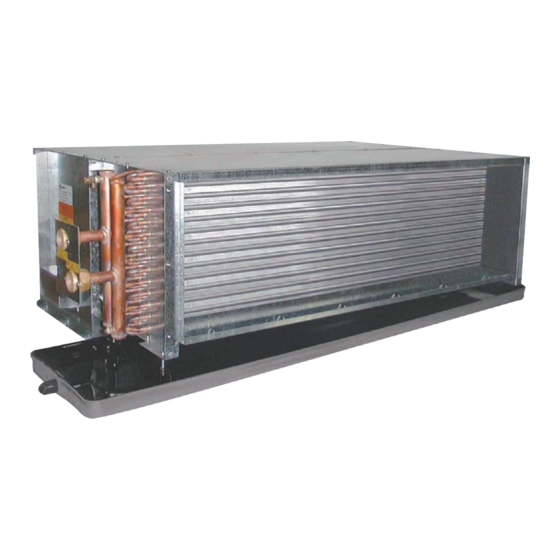
Cooling Basic Unit direction, vibration isolating mountings to while coil has one set of connection, hot The Trane Model HCCA fan coil unit ensure vibration free operation and water heating option have two sets of consisting rigid galvanized steel casing, minimum noise. - Page 4 Figure 1 : General Illustration Of Unit © American Standard Inc. 2003 HCCA-SVX01A-EN...
-
Page 5: Hcca Model Designation
N = Without Return Plenum / No Filter F = 4 Row Cooling, Left Hand Valve / With Trane Wall Mounted Zone Sensor / F = With Rear Return Plenum / No Filter J = 3 Row Cooling, 1 Row Heating, Right Hand... -
Page 6: Installation
Receiving And Handling units: threaded rods furnished by the installer. Trane HCCA Fan Coil units are packaged in Holes are provided at the top of the unit, see individual cartons for maximum protection 1. Allow adequate space for the unit and free... -
Page 7: Duct Connections
Duct Connections Piping Electrical Connections Minimum 24 gauge galvanized sheet metal Coil connections For wiring and installion, refer to the wiring duct (supplied by the installer) is recommended To complete piping connections, attach the diagram decals on each unit located on coil to be attached to duct collars provided at the water piping with famale connections copper end panel. - Page 8 Table 1 : HCCA Unit Operating Figure 2 : Typical Installation With Rear Return Plenum Weights HCCA Unit without Plenum Operating Weights (kg) Row/Size 3ROW 4ROW 6ROW HCCA Unit with Plenum Operating Weights (kg) Row/Size 3ROW 4ROW 6ROW Table 2 : HCCA Unit Net Weights HCCA Unit without Plenum Net Weights (kg) Row/Size 3ROW...
-
Page 9: Coil Connections
Coil Connections Figure 4 : Model HCCA Coil Connections Note:Dimension in mm 25.4mm = 1 inch Cooling & Heating Coil Connection Dimension Unit Cooling 3 Row 4 Row 3 Row 4 Row 3 Row 4 Row 3 Row 4 Row Coil Type Heating 1 Row... -
Page 10: Dimension Data
Dimension Data Figure 5 : HCCA Unit Without Plenum Figure 6 : HCCA Unit With Rear Return Plenum © American Standard Inc. 2003 HCCA-SVX01A-EN... - Page 11 *758 NOTES: *Represent outine dimension of unit 1. Dimension is mm. 2. Right hand coil connection shown. 3. External wiring, controls not supplied by Trane. 4. See coil connections size and location. 5. D=standard drain pan, D1=extend drain pan. HCCA-SVX01A-EN...
-
Page 12: Wiring Diagrams
Wiring Diagrams Figure 9 : Model HFCA Wiring Diagrams Factory Std. Wiring of HCCA-Standard Motor Unit Size Power Supply (Volt/Hz) 220/50 220/60 220/50 220/60 220/50 220/60 220/50 220/60 Yellow Black Yellow Black High Black Black Blue Yellow Blue Yellow Wire Color Medium Yellow Yellow... -
Page 13: Installation Checklist
Installation Checklist The following checklist is provided as an • Units are checked for shipping damage. abbreviated guide to the detailed installation • Unit location is prepared for weight, procedures given in this manual. This list leveling and service access. should be used by the installer to ensure •... -
Page 14: Start Up/Operation
Operation Although the units may operate with variable Two basic methods of fan coil control are speed control, Trane cannot warranty proper available: (1) fan speed control and (2) operation with any particular control. Contact cycling of the waterflow to the unit coil. The Trane if you have questions. -
Page 15: Maintenance
The services of a qualified water treatment specialist should be engaged to determine what treatment if any, is advisable. The Trane Company assumes no liability for the results of the use of untreated or improperly treated water. - Page 16 Figure 10 : HCCA Filter Assembly Figure 11 : HCCA Plenum Assembly © American Standard Inc. 2003 HCCA-SVX01A-EN...
- Page 17 Changing Fan Housing and Fan Wheel After replacing the motor, make sure the fan Trane Company. The motor should be The fan housing and fan wheel can be wheel is balanced and centered in the fan...
- Page 18 Figure 12 : Fan Board Assembly Figure 13 : HCCA Drain Pan Assembly © American Standard Inc. 2003 HCCA-SVX01A-EN...
- Page 19 The replacement parts are available through follwing steps: 1. Loosen nuts which fasten the drain- pan the Trane Company or local Sales suspension screw with unit casing Representative. When ordering parts, the 1. Turn off the electrical power source and together.
- Page 20 3600 Pammel Creek Road La Crosse, Wl 54601-7599 Supersedes HCCA-SVX01A-EN-1001 Stocking location Taipei, Taiwan http : // www.trane.com Since The Trane Company has a policy of continuous product improvement, it reserves the right to change design and An American-Standard Company specifications without notice.
Need help?
Do you have a question about the Maxxum HCCA Series and is the answer not in the manual?
Questions and answers