Advertisement
Quick Links
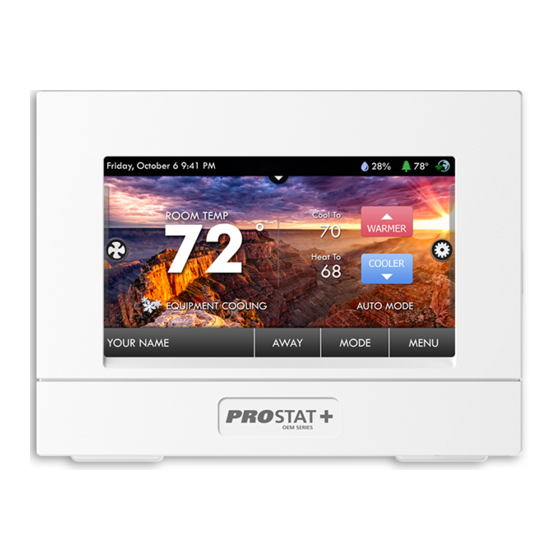
Residential Smart Wi-Fi Thermostat
PSP4273
1 Specifications 2 Installation Instructions and Wiring 3 Installer Setup
4 Factory Defaults 5 Technician Setup & Calibration 6 Troubleshooting
7 Limited Warranty
1 Specifications
•
Geofencing with Optional Plug-In Module
•
Choose 7-Day, 5/1/1 day or 1-Day
Programming
•
365-Day Vacation Programming
(when connected to ProStat+ Web Portal)
•
Smart recovery auto-adjusts Morning
start time
•
Setpoint Limiting
•
Energy Watch tracks heating, cooling,
and aux heat run times
•
Adjustable Timers & Deadbands
Between Stages
•
CA Title 24 Compliant
P4273_Installer man.indd 1
P4273_Installer man.indd 1
Up to 4-heat / 2-cool with Humidity Control
OPTIONAL Wi-Fi and Local API with module
WARNING
CAUTION
Follow Installation Instructions carefully. Disconnect Power to the Heater/
Air Conditioner before removing the old thermostat and installing the new
thermostat.
Installer Manual
•
Fresh Air Ventilation Control
•
Controls Humidification,
Dehumidification & Reheat
•
Dual Fuel Compatible
•
Condensate overflow warning system
•
Control to, or Monitor a 2nd Remote
Sensor, baby's room or game room, etc.
•
Choice of English, Spanish or French
For Scrolling Display
•
OEM-Branded Equipment
Badges Included
© Copyright 2021, All Rights Reserved
6/9/21 11:23 A
6/9/21 11:23 A
Advertisement

Related Manuals for PROSTAT+ OEM Series


Summary of Contents for PROSTAT+ OEM Series
- Page 1 Installer Manual Residential Smart Wi-Fi Thermostat PSP4273 Up to 4-heat / 2-cool with Humidity Control OPTIONAL Wi-Fi and Local API with module 1 Specifications 2 Installation Instructions and Wiring 3 Installer Setup 4 Factory Defaults 5 Technician Setup & Calibration 6 Troubleshooting 7 Limited Warranty WARNING CAUTION...
-
Page 2: Installation Instructions
2 Installation Instructions Remove and Replace the old thermostat To install the thermostat properly, please follow these step by step instructions. If you are unsure about any of these steps, call a qualified technician for assistance. • Installation tools: Small flat blade screwdriver, Phillips screwdriver, wire cutters and wire strippers. - Page 3 The ProStat + Thermostat Backplate To remove the thermostat backplate: Gently separate the display from the base by pulling from the center. To remove the thermostat backplate from the wall: pry with screwdriver in either slot to remove back plate 24 VAC return 24 VAC common Fan relay...
- Page 4 Check Dip Switch Ensure which switch is correct for your system. Dip switches are located on the back of the thermostat. ELEC RV=O RV=B ELEC GAS/ELEC HEATPUMP RV=O RV=B GAS/ELEC HEATPUMP 1. When GAS/ELEC or HEATPUMP is set for GAS/ELEC: This switch (GAS or ELEC) controls how the ELEC thermostat will control the Fan (G) terminal in...
- Page 5 Sample Wiring Diagrams Conventional Heating and Cooling Systems 3 Wire, Heat Only 4 Wire, Cool Only Residential & Commercial 1 Stage Heating Residential & Commercial 1 Stage Cooling. with no Fan. 24VAC Power 24VAC Power 24VAC Common 24VAC Common 1st Stage Cool W1/O/B 1st Stage Heat ELEC...
- Page 6 Heat Pump Systems 5 Wire, 1 Stage Cooling, 1 Stage Heat 6 Wire, 1 Stage Cooling, 2 Stage Heat Residential & Commercial Heat Pump with Residential & Commercial Heat Pump with O Reversing Valve O Reversing Valve 24VAC Power 24VAC Power 24VAC Common 24VAC Common W1/O/B...
- Page 7 5 Wire, 1 Stage Cooling, 1 Stage Heat 6 Wire, 1 Stage Residential & Commercial Heat Pump with Residential & Com O Reversing Valve O Reversing Val Heat Pump Systems with Dual Fuel 24VAC Power 24VAC Common W1/O/B Reversing Valve W1/O/B 1st Stage Compressor (Cool or Heat)
-
Page 8: Installer Setup
3 Installer Setup Setup Step Table FD = Factory Default Setting See User Manual for steps 1 - 8 Step# Description Pg# Range Prog Mode Non, 1 Day, 5/2 Day, 7 Day 7 Heat/Cool/Auto/Off, Heat/Cool Available Modes Heat/Cool/ /Off, Heat/Off, Cool/Off Auto/Off Backlight On, Off... - Page 9 FD = Factory Default Setting Step# Description Pg# Range Minutes Between 1st and 2nd Stage 0 - 60 Minutes Minutes Between 2nd and 3rd Stage 0 - 60 Minutes Minutes Between 3rd and 4th Stage 0 - 60 Minutes 2nd StageTurnoff Point Deadband, Setpoint Deadband 3rd StageTurnoff Point...
- Page 10 FD = Factory Default Setting Step# Description Pg# Range Aux Output Time, Temp, External, Free Time Cooling, Venting Aux Output Program Days 1 Day, 5/2 Day, 7 Day Day Of Week To Program Sunday - Monday (S - M) MTWTFSS Aux Output Start Time 12am - 12am Aux Output Stop Time...
- Page 11 How to Change Settings in the Setup Screens To enter Advanced Setup, press the SETUP button, then press MODE. Use the WARMER or COOLER buttons to adjust the value of your selection. Press MODE to advance to the next setup step. Press SETUP again to leave the setup screens. WARMER WARMER MODE...
- Page 12 Runtime Alerts & Reset (Setup Steps 11-19) Heating and Cooling System Runtime - Energy Watch (Setup steps 11-13) Current Heat Runtime Hours (Setup Step 11) - This counter keeps track of the number of hours the system has run in Heating. Press FAN to reset. Current Aux Strip Heat Runtime Hours (Setup Step 12) - This counter keeps track of the number of hours the system has run in Auxiliary Heating.
- Page 13 Scrolling Display (Setup Steps 20, 21) Language (Setup Step 20) - Setup step instructions on the scrolling display can be set for English, Spanish, or French. Scrolling Display Method (Setup Step 21) - This option allows the user to choose how the scrolling text is displayed.
- Page 14 Staging & Cycle Timers (Setup Steps 25-31) Cycles Per Hour (Setup Step 25) - The Cycles Per Hour setting may limit the number of times per hour your HVAC unit may energize. For example, at a setting of 6 cycles per hour the HVAC unit will only be allowed to energize once every 10 minutes.
- Page 15 Auxiliary Heat Lockout (setup steps 58 - 59) This feature allows the auxiliary heat for a heat pump (W2 and W3) to be locked out above a specific outdoor temperature. These steps will only appear if the thermostat jumper J1 is set for Heat Pump and J3 is set for Electric Heat.
- Page 16 1st Stage Deadband (Setup Step 32) - Specifies the minimum temperature difference between the room temperature and the desired setpoint before the first stage of heating or cooling is allowed to turn on (1 - 6 degrees). For example, if the heat setpoint is 68˚ and the 1st Stage deadband is set to 2 degrees, the room temperature will need to fall to 66˚...
- Page 17 to bring the temperature to its correct setting at exactly 6am. The thermostat learns from experience, so please allow 4-8 days after a program change or after initial installation to give Comfort Recovery time to adjust. If used with a heat pump, electric strip heat will be disabled while Comfort Recovery is active.
- Page 18 Wireless Remote To Use (setup step 48) - Specifies which single wireless remote sensor is to be used for control. This step only appears when prior step setting is Wireless Remote. Fahrenheit or Celsius (Setup Step 65) - This feature allows the thermostat to display temperature in Fahrenheit or Celsius.
- Page 19 Humidity Output Normally Closed - means voltage is sent to the HUM output when there is no demand for humidity. Dehumidify Output Polarity (Setup Step 81) Dehumidify Output Normally Open - means no voltage is sent to the DEHUM output when there is no demand to dehumidify. Dehumidify Output Normally Closed - means voltage is sent to the DEHUM output when there is no demand to dehumidify.
- Page 20 Aux Output Stop Time (Setup Step 71) - Specifies the time of each day when the Aux output will turn off. Copy (Setup Step 72) - This step only appears if Aux Output Days (Setup Step 58) is set for 7 DAY programmable output days. Press COOLER and then OUTDOOR to copy. Press WARMER and then OUTDOOR to program another day with a different setting.
- Page 21 Free Cooling (setup steps 75 - 76) To use Free Cooling, setup step 67 must be set to ‘FREE COOLING’. Free Cooling is an energy saving way to boost the efficiency of your air conditioning system by bringing in fresh air from the outside. The installation of a Free Cooling damper and outdoor temperature sensor are required.
- Page 22 FDD - If FDD is selected when the dry contact is active, the scrolling display will read EQUIPMENT FAULT. This error message will disappear when the Dry Contact is idle. Press the Vacation button to enter Vacation/Away programming (no Wi-Fi Module detected). If there is not a period active: Use the Warmer and Cooler buttons to choose the number of days desired to run the Vacation feature.
- Page 23 Static Cool Setpoint (Setup Step 89) Static Heat Setpoint (Setup Step 90) Specifies the setpoints that will come into use during an event when the PRICE DEPENDENT ACTION is set to OBSERVE STATIC SETPOINT Cool Setpoint Offset (Setup Step 91) Heat Setpoint Offset (Setup Step 92) Specifies how much the current setpoints in effect prior to an event will be altered during an event when the PRICE DEPENDENT ACTION is set to OBSERVE SETPOINT...
- Page 24 Locking/Unlocking the Keypad To prevent unauthorized use of the thermostat, the front panel buttons may be disabled. To disable, or ‘lock’ the keypad, press and hold the MODE button. While holding the MODE button, press the WARMER and COOLER buttons together, and the icon will appear on the display.
-
Page 25: Factory Defaults
Factory Defaults If, for any reason, you desire to return all the stored settings back to the factory default settings, follow the instructions below. WARNING: This will reset all Time Period and Advanced Programming to the default settings. Any information entered prior to this reset will be permanently lost. - Page 26 Technician Setup & Calibration To enter Technician Setup, press and hold the SETUP button for 10 seconds. After all the icons appear, press MODE. The version number of the thermostat will appear in the scrolling text. Press MODE to advance to the next step. Use the WARMER or COOLER buttons to adjust the value of your selection.
- Page 27 To enter Technician Setup, press and hold the SETUP button for 10 seconds until all the icons appear. Follow the next steps to view settings and test equipment. Press MODE to view the version numbers of the thermostat. Press MODE again to view the jumper settings and current state of the Dry Contact terminal.
-
Page 28: Troubleshooting
Troubleshooting • SYMPTOM: The air conditioning does not attempt to turn on. CAUSE: The compressor timer lockout may prevent the air conditioner from turning on for a period of time. REMEDY: Consult the manual Setup section to defeat the Cycles Per Hour. •... -
Page 29: Limited Warranty
7 Limited Warranty PSP Series - Thermostat Models: PSP1100, PSP1152, PSP2100, PSP2152, PSP2270, PSP2270C, PSP2111, PSP4272, PSP4273, PSP4271C, PSP4272C, PSP4272RT, PSP4273RT, PSP4272CT, PSP4273CT Who Is Providing The Warranty? For further information about this warranty contact This warranty is provided to you by Goodman Consumer Affairs at (877) 254-4729 or by mail to 19001 Manufacturing Company, L.P. - Page 30 (3) For products on which a manufacture date is NOT LIMITED TO LOST PROFITS, LOSS OF USE OF A indicated, if the date the owner purchases the CONTROL, EXTRA UTILITY EXPENSES, OR DAMAGES TO PROPERTY. residence from the builder or the date the product is originally installed cannot be verified, the installation Some states and provinces do not allow the exclusion or date is three months after the manufacture date.
- Page 31 of this control, any warranty upon the unit, or the unit’s 92614, www.jamsadr. com), or, subject to our approval, condition. It also includes determination of the scope or any other arbitration organization. In addition, Canadian applicability of this Arbitration Clause. The arbitration residents may choose the ADR Institute of Canada (234 requirement applies to claims in contract and tort, Eglinton Ave.
- Page 32 Innovation, Science and Economic Development Canada ICES-003 Compliance Label: CAN ICES-3 (B)/NM8-3(B) rev. 2 06/09/2021 88-1475 P4273_Installer man.indd 31 P4273_Installer man.indd 31 6/9/21 11:23 A 6/9/21 11:23 A...
Need help?
Do you have a question about the OEM Series and is the answer not in the manual?
Questions and answers