
Related Manuals for ABB Vmax


Summary of Contents for ABB Vmax
-
Page 1: Table Of Contents
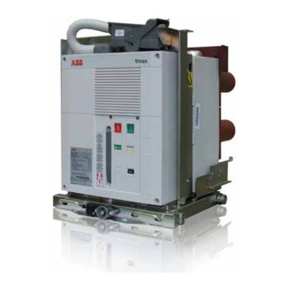
Medium voltage products Vmax Medium voltage vacuum circuit-breaker ANSI: ... 15 kV; ... 1200 A; ... 31.5 kA For your safety! Foreword 1.1. Introdution 1.2. Environmental protection programme 1.3. Vacuum interrupter quenching principle 1.4. Information on this booklet 1.5. Drawout 1.6. -
Page 3: For Your Safety
For your safety! • Make sure that the installation room (spaces, divisions and ambient) is suitable for the electrical apparatus. • Check that all the installation, putting into service and maintenance operations are carried out by qualified personnel with suitable knowledge of the apparatus. • Make sure that the standard and legal prescriptions are complied with during installation, putting into service and maintenance, so that installations according to the rules of good working practice and safety in the work place are constructed. • Strictly follow the information given in this instruction manual. • Check that the rated performance of the apparatus is not exceeded during service. • Check that the personnel operating the apparatus have this instruction manual to hand as well as the necessary information for correct intervention. • Pay special attention to the notes indicated in the manual by the following symbol: ReSPonSible behaviouR SafeguaRdS youR own and otheRS’ Safety! foR any RequeStS, PleaSe ContaCt the abb aSSiStanCe SeRviCe. -
Page 4: Foreword
ISO 14000 Standards (Guidelines for For correct use of the product, please read it carefully. environmental management). Like all the apparatus we manufacture, the Vmax/w and The production processes are carried out in compliance Vmax circuit-breakers are designed for different installation with the Standards for environmental protection in terms of configurations. -
Page 5: Information On This Booklet
The standard in direct current, specified in the IEC, VDE and ANSI/IEEE fixed version of Vmax must be installed by the customer in a Standards, cannot be used; minimal enclosure so as to guarantee a minimum degree of –... -
Page 6: Introduction And Safe Practices
The specific ratings of each model circuit-breaker are listed be followed. on the individual nameplates. The Vmax/w and Vmax circuit- breakers are protective devices. As such, they are maximum Only qualified persons, as defined in the National Electric rated devices. -
Page 7: Standard And Regulations
+ 35 °C 2.3.1. fabrication Minimum for indoor installation - 30 °C The Vmax, Vmax/w circuit-breakers conform to the following Standards: humidity – DIN VDE 0670, part 104, and IEC 62271-100 The average value of the relative humidity, measured for a period longer –... -
Page 8: Reveiving, Handling, And Storage
Should any damage or irregularity be noted in the supply the carton(s) to determine if any damage or loss was on unpacking, notify Abb (directly or through the agent or sustained during transit. If damage or indication of rough supplier) as soon as possible and in any case within five days handling is evident, file a damage claim at once with the of receipt. -
Page 9: Handling
Vmax/w and Vmax circuit-breaker shipping containers are Care must be taken not to damage the secondary plug designed to be handled by fork lift (not supplied) Fig. 2. -
Page 10: Storage
3.3. Storage when a period of storage is foreseen, our workshops can (on CAUTION request) provide suitable packing for the specified storage conditions. On receipt the apparatus must be carefully unpacked and checked as described in Checking on receipt. If immediate installation is not possible, the packing must be THE SHIPPING CONTAINERS PROVIDED replaced, using the original material supplied. -
Page 11: Description
4.1. General 4.2. Reference Standards The Vmax series of circuit-breakers are pieces The Vmax circuit-breakers conform to the IEC 62271-100, of apparatus under vacuum for indoor installation; ANSI C37.04 – C37.54 – C37.09 – C37.55 Standards and for the electrical performances, please refer those of major industrialized countries. - Page 12 4.3.1. general characteristics of Standard fittings for fixed circuit-breakers fixed circuit-breakers vmax The basic versions of the fixed circuit-breakers are three-pole and fitted with: – EL type manual operating mechanism – mechanical signalling device for closing springs charged/ discharged – mechanical signalling device for circuit-breaker open/closed – closing pushbutton –...
- Page 13 The withdrawable circuit-breaker is fitted with special locks The withdrawable circuit-breakers (see fig. 7) are available for on the front crosspiece, which allow hooking up into the Abb PowerCube modules. corresponding couplings of the switchgear. They consist of a truck on which the supporting structure of The locks can only be activated by the handles with the truck the circuit-breaker is fixed.
- Page 14 – Closing and opening pushbutton – Operation counter – Set of ten auxiliary circuit-breaker open/closed contacts – Lever for manually charging the closing springs – Isolating contacts Circuit-breaker vmax/w 15 use in switchgear/enclosure PowerCube IEC 62271-100 • CEI EN62271-100 (file 7642) • Standards C37.54 - C37.09 - C37.04 - C37.55 •...
-
Page 15: Characteristics Of The Electrical Accessories
– Cord with connector (plug only) for auxiliary circuits, with striker pin on request, which does not allow connection of the plug in the socket if the rated current of the circuit- breaker is different from the rated current of the panel –... -
Page 16: Preliminary Operations
(IP2X) from in, and anti-clockwise for racking-out, until the end-of-run the front towards live parts.The fixed version of Vmax circuit- positions are reached. breaker must be installed by the customer so as to guarantee Circuit-breaker racking- in/-out must be carried out gradually a minimum degree of protection as for C37.20.2 and C37.55... - Page 17 Please note that auxiliary circuits must be energized with 2 kV (maximum test voltage) as per standards indications. Connection of the auxiliary circuit for vmax fixed circuit-breaker Connection of the circuit-breaker auxiliary circuits must be made by means of the proper terminal box mounted inside the circuit-breaker and the wires must pass through the connector (1) (Fig.
- Page 18 4.5.7. Power circuit connections earthing of fixed circuit-breakers vmax For the fixed version circuit-breaker, carry out earthing by – General recommendations means of the special screws marked with the relative symbol – Select the cross-section of the conductors according to (see fig. 10). the service current and the short circuit current of the Clean and degrease the area around the screw to a diameter installation.
- Page 19 4.5.8. operating and signalling parts undervoltage release mechanical override (on request) override activated undervoltage release disabled. The circuit-breaker can be closed even if the undervoltage release is not supplied. override disabled undervoltage release activated. The circuit-breaker can only be closed if the undervoltage release is supplied with power. Caption 1 key lock (if provided) (*) 2 Lever for manually charging the closing springs 3 Coupling lever for racking-out operation (only for withdrawable circuit-breakers)
-
Page 20: Putting Into Service
– check that there is a sufficient exchange of air in the INTO SERVICE MuST bE CARRIED OuT installation place to avoid over temperatures; by Abb PERSONNEL OR by SuITAbLy – supply the auxiliary circuits with power; quALIFIED CuSTOMER PERSONNEL wITH –... - Page 21 item inspected Procedure Positive check key lock (if provided). Open the circuit-breaker, keep the opening pushbutton Neither manual nor electrical closing takes depressed, then turn the key and remove it from the housing. place. Attempt the circuit-breaker closing operation. Put the key back in and turn it 90°. both electrical and manual closing take place Carry out the closing operation.
- Page 22 4.6.2. Safety indications 4.6.4. Racking vmax/w: (figure 7) Vmax circuit-breakers guarantee a minimum IP2X degree of Vmax/w circuit-breakers are designed with two positive protection when installed in the following conditions: racking positions: Disconnect, Connect. In the Disconnect – fixed circuit-breaker, installed behind a protective metallic net position the shutters are closed.
- Page 23 4.6.6. Connect through disconnect 4.6.7. Connect through disconnect 1. Perform a visual inspection of the circuit-breaker: emergency rack out: (Figure 12) a. Verify Close/Open Indicator shows OPEN. 1. In the case of a locking magnet –RL2 fault, in an b. Verify switchgear door is CLOSED. emergency the truck can be racked out manually following 2.
- Page 24 Secondary disconnects (b) Shutters wheel rails Compartment slots (A) fig. 13 Racking screw collar fig. 14...
- Page 25 4.6.8. Circuit-breaker closing and opening operations each closing operation until the yellow signaling device (7) Circuit-breaker operation can be either manual or electrical appears. (fig. 15). If the power is cut off during charging, the geared motor stops. Automatically the motor spring charging starts a) Manual spring charging operation recharging the springs when the power returns.
- Page 26 4.6.9. operating mechanism description once the closing spring is charged completely: when the motor is activated or manual charging lever is is 4 A part of the closing springs force works on the closing moved: hook through the closing lever assembly and the pin 1 - 1 The operating mechanism shaft turns (1 - fig. 16) fig.17 of the cams/toggle assembly 2 The cams on the shaft move the closing lever assembly 5 The closing hook, remains locked by the closing shaft 2 -...
- Page 27 when you push the closing pushbutton: 13 The long levers reach the settled position 8 The closing shaft 1 - fig.18 turns and releases the closing 14 The contact springs inside the poles and the opening hook spring inside the frame are charged 9 The closing springs unloads their energy on the closing 15 A part of the contact springs and opening spring load lever assembly works on the long levers but the long levers remain in their...
- Page 28 once the Cb is closed: when you push the opening pushbutton: The motor gear (if present) turns automatically the operating 18 The opening shaft 1 - fig. 21 turns and releases the mechanism shaft (20) and the conditions of the points 1. 2. opening hook and 3. are satisfied. 19 The opening hook releases the central hook of the cams/ toggle assembly 20 The long levers of the cams/toggle assembly are free now...
-
Page 29: Standard Fittings For Circuit-Breaker
4.7. Standard fittings for circuit-breaker 4.7.2. Standard fittings for fixed circuit-breaker series The basic versions of the fixed circuit-breakers are three-pole and fitted with: 4.7.1. Standard fittings for withdrawable 1 EL type manual operating mechanism circuit-breaker series 2 mechanical signalling device for closing springs charged/ The basic versions of the withdrawable circuit-breakers are discharged three-pole and fitted with: 3 mechanical signalling device for circuit-breaker open/... -
Page 30: Operation, Installation And Maintenance
(fig.2A) in the test/ isolation position. 5.1.2. interlocks in the case where abb DANGER withdrawable trucks are used 1) The Vmax/w circuit-breaker can only be closed when the withdrawable truck is in the test or service position. 2) A mechanical interlock positioned on the withdrawable MODIFICATION TO INTERLOCkS CAN... - Page 31 The rotating locking device (1) (fig. 25) on the circuit- slide locking device must be pulleed down as shown (4) breaker can be used for this purpose: if the Vmax circuit- (fig. 25a). This prevents movement closing circuit-breaker breaker is closed, the rotating locking device is down close in intermediate position.
-
Page 32: Maintenance
5.2.1. general Vacuum circuit-breakers are characterised by simple, sturdy construction and long life. Vmax circuit-breakers are designed for a minimum amount The drive is maintenance-free for its whole operating life and of maintenance. Circuit-breakers in a clean, non-corrosive only requires functional inspections. - Page 33 Remove the front cover by unfastening its screws and correct the degree of vacuum of the interrupters. Typical useful life expectancy of a Vmax vacuum circuit- any loose or missing hardware . breaker is determined by the following factors: Always lubricate the working surface of the moving parts.
- Page 34 5.2.4. inspections and functional tests functional test – Make the circuit-breaker safe by discharging the closing interruption devices in general springs (close and open the circuitbreaker by means of the – Carry out regular inspections to check that the interruption closing and opening pushbuttons). devices are in good condition. –...
- Page 35 Only use halogen-free detergents and never trichloroethane, These operations can only be carried out by Abb personnel trichloroethylene or carbon tetrachloride! or suitably qualified and specially trained personnel.
- Page 36 PERSONNEL, RESPONSIbILITy FOR THE Dismantling and replacement of the interrupter assembly INTERVENTIONS REMAINS wITH THE can only be carried out by Abb personnel or by qualified CuSTOMER. and specially trained personnel, especially for the necessary THE REPLACEMENT OF PARTS NOT adjustments.
-
Page 37: Truck
5.3. Truck with the circuit-breaker outside the cell, rotate the racking (Refer to Fig. 27) screw as though racking the circuit-breaker to the Connect position. This process will expose surfaces inside the truck The truck requires visual inspection of hardware, lubrication, that need to be inspected and lubricated. - Page 38 Primary low-frequency withstand test voltage Lubrication on the primary contacts should be inspected during routine maintenance. use only grease Isoflex Topas Nb52 (Abb No. GCE0007249 P100, 1 Pt. can).
- Page 39 To verify the integrity of the vacuum interrupters perform the 5.3.3. application of the X-ray following low-frequency withstand voltage test: 1. Open the circuit-breaker (no control power supplied to the emission standards circuit-breaker). One of the physical properties of vacuum insulation is the a. Connect the high potential lead to one terminal. possibility of X-ray emission when the interrupter contacts are open.
-
Page 40: Servicing
– more resistant deposits of dirt can be removed using a Dismantling and replacement of the interrupter assembly slightly alkaline domestic cleanser; can only be carried out by Abb personnel or by qualified • cleaning insulating surface and conductive parts: and specially trained personnel, especially for the necessary –... -
Page 41: Spare Parts And Accessories
PARTS/ACCESSORIES MuST bE CARRIED OuT – Shunt closing release FOLLOwING THE INSTRuCTIONS ENCLOSED – Spring charging geared motor with electrical signalling of wITH THE SPARE PARTS, by Abb PERSONNEL springs charged OR by SuITAbLy quALIFIED CuSTOMER – Contact signalling geared motor protection circuit-breaker... -
Page 42: Overall Dimensions
8. Overall dimensions Vmax - Fixed circuit-breaker ANSI: 15 kV - 1200 A - 25...31.5 kA 1vCd003279_v3198 421 16,57 35 1,38 133 5,24 133 5,24 416 16,37 364 14,33 291 11,46 1-8-10 2-10 29 1,12 188 7,39 336 13,23 28 1,1... - Page 43 Vmax/w - withdrawable circuit-breakers for PowerCube ANSI: 15 kV - 1200 A - 25...31.5 kA 1vCd003280_v2856 492 19,37 15,5 0,61 123,5 4,86 234 9,19 42,5 1,67 1-8-10 2-10 39 1,53 36 1,42 52 2,05 25 0,98 28 1,09 320 12,6...
-
Page 44: Electric Circuit Diagram
9. Electric circuit diagram Circuit-diagram of Vmax circuit-breaker in withdrawable version for PowerCube with EL operating mechanism. For other circuit-breakers, please consult us. The diagram indicates the following conditions: – circuit-breaker off and connected – circuits de-energized – closing springs discharged... - Page 48 Caption = Connector for the circuit-breaker circuits. = Reference number of diagram figure. = See note indicated by the letter. -Xb2..9 = Connectors of accessories. = Circuit-breaker accessories. -Xb1 = Switchboard terminal board (mounted externally to = Device for the supervision of shunt opening release the circuit-breaker).
- Page 49 = Spring charging-motor circuit (see note C). A) The circuit-breaker is delivered complete with the Fig. 2 = Shunt closing release (antipumping is achieved accessories listed in the Abb order acknowledgement only. mechanically). To draw up the order examine the catalogue. Fig. 3 = Locking magnet.
-
Page 50: Product Quality And Environmental Protection
9001 and by the EMS according to ISO 14 001. End of life of product The Abb company is committed to complying with the relevant legal and other requirements for environment protection according to the ISO 14 001 standard. The duty of company is to facilitate subsequent recycling or disposal at the end of product life. During disposal of the product, it is always necessary to act in accordance with local legal requirements in force. - Page 52 The data and illustrations are not binding. we reserve the right to make changes without notice in the course of technical development of the product. © Copyright 2011 Abb. All rights reserved. your sales contact: www.abb.com/contacts More product information: www.abb.com/productguide...
Need help?
Do you have a question about the Vmax and is the answer not in the manual?
Questions and answers