
Subscribe to Our Youtube Channel
Related Manuals for ABB VD4 12.06.16 p150


Summary of Contents for ABB VD4 12.06.16 p150
- Page 1 All manuals and user guides at all-guides.com Installation and service instructions 12 ... 24 kV - 630 ... 2500 A - 16 ... 31.5 kA...
- Page 2 All manuals and user guides at all-guides.com...
- Page 3 Pay special attention to the danger notes indicated in the manual by the following symbol: Responsible behaviour safeguards your own and others’ safety! For any requests, please contact the ABB Assistance Service.
- Page 4 All manuals and user guides at all-guides.com Index Introduction II. Programme for environmental protection 1. Packing and transport 2. Checking on receipt 3. Storage 4. Handling 5. Description 5.1. General information 5.2. Reference Standards 5.3. Fixed circuit-breaker 5.4. Withdrawable circuit-breaker 5.5.
- Page 5 All manuals and user guides at all-guides.com Introduction This publication contains the information needed to install medium voltage VD4 circuit-breakers and put them into service. For correct use of the product, please read it carefully. Like all the apparatus we manufacture, the VD4 circuit-breakers are designed for different installa- tion configurations.
- Page 6 All manuals and user guides at all-guides.com Packing and transport Should any damage or irregularity be noted in the supply on unpacking, notify ABB (directly or The circuit-breaker is shipped in special pack- through the agent or supplier) as soon as possi- ing, in the open position and with the springs ble and in any case within five days of receipt.
- Page 7 All manuals and user guides at all-guides.com 4. Handling During handling, take great care not to stress the insulating parts and the terminals of the cir- Before carrying out any operations, always make cuit-breaker. sure that the operating mechanism springs are discharged and that the apparatus is in the open The apparatus must not be handled by position.
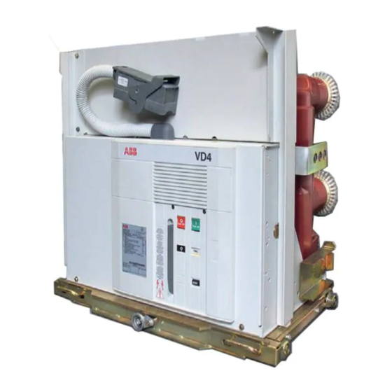
- Page 8 5.3. Fixed circuit-breaker For special installation requirements, please con- The fixed circuit-breaker (fig. 4) is the basic ver- tact ABB. sion complete with structure and front protection The following versions are available: screen. The fixing holes are made in the lower –...
- Page 9 All manuals and user guides at all-guides.com Caption 6 Signalling device for closing springs charged/discharged 1 Lever for manual closing spring charging 7 Operation counter 2 Signalling device for circuit-breaker open/closed 8 Terminals 3 Rating plate 9 Earthing screw 4 Opening pushbutton 10 Delivery terminal box 5 Closing pushbutton 11 Cabling connection...
- Page 10 W = 570 W = 570 W = 700 W = 700 W = 570 W = 700 W = 700 W = 700 VD4 12.06.16 p150 VD4 12.06.20 p150 VD4 12.06.25 p150 31.5 VD4 12.06.32 p150 1250 VD4 12.12.16 p150 1250 VD4 12.12.20 p150...
- Page 11 All manuals and user guides at all-guides.com 5.3.3. Standard fittings for fixed circuit-breakers The basic versions of the fixed circuit-breakers are three-pole and fitted with: – EL type manual operating mechanism – mechanical signalling device for closing springs charged/discharged – mechanical signalling device for circuit-breaker open/closed –...
- Page 12 All manuals and user guides at all-guides.com 5.4. Withdrawable circuit-breaker The withdrawable circuit-breaker is fitted with The withdrawable circuit-breakers (see fig. 5) are special locks on the front crosspiece, which al- available for UniGear type ZS1 and UniSafe low hooking up into the corresponding couplings switchgear.
- Page 13 All manuals and user guides at all-guides.com Caption 5 Closing pushbutton 11 Locks for hooking into the fixed part 1 Lever for manually charging the closing 6 Signalling device for closing springs charged/ 12 Handles for activating the locks (11) springs discharged 13 Strikers for activating the contacts placed in...
- Page 14 All manuals and user guides at all-guides.com 5.4.2. Types of withdrawable circuit-breakers available for UniGear type ZS1 switchgear VD4/P withdrawable circuit-breaker for UniGear type ZS1 switchgear Rated uninterrupted current (40°C) [A] W = 650 W = 800 W = 1000 W = 1000 W = 800 W = 1000...
- Page 15 All manuals and user guides at all-guides.com VD4/D withdrawable circuit-breaker for UniGear type ZS1 switchgear Rated uninterrupted current (40°C) [A] W = 650 W = 800 W = 1000 W = 1000 W = 800 W = 1000 W = 1000 Circuit-breaker type I = 150 I = 210...
- Page 16 All manuals and user guides at all-guides.com 5.4.4. General characteristics of withdrawable circuit-breakers for UniSafe switchgear Circuit-breaker VD4/P 12 Standards IEC 62271-100 CEI 17-1 (File 1375) Rated voltage Ur [kV] Rated insulation voltage Us [kV] Withstand voltage at 50 Hz Ud (1 min) [kV] Impulse withstand voltage Up [kV]...
- Page 17 All manuals and user guides at all-guides.com VD4/P 17 VD4/P 24 17.5 17.5 50-60 50-60 1250 1250 1600 2000 2500 1250 1600 2000 – – – 31.5 31.5 31.5 31.5 31.5 31.5 31.5 – – – – – – – 31.5 31.5 31.5...
- Page 18 All manuals and user guides at all-guides.com 5.4.5. Types of withdrawable circuit-breakers available for UniSafe switchgear VD4/P withdrawable circuit-breaker for UniSafe switchgear Rated uninterrupted current (40°C) [A] W = 600 W = 750 W = 750 W = 1000 W = 800 W = 1000 Circuit-breaker type I = 150...
- Page 19 All manuals and user guides at all-guides.com 5.4.6. Standard fittings for withdrawable circuit-breakers for UniSafe switchgear The basic versions of the withdrawable circuit-breakers are always three-pole and fitted with: – EL type manual operating mechanism – mechanical signalling device for closing springs charged/discharged –...
- Page 20 All manuals and user guides at all-guides.com 5.5. Characteristics of the electrical Auxiliary contacts of the circuit-breaker accessories 24 ... 220 V AC-DC Rated current: = 10 A Shunt opening release (-M01); Insulation voltage: 2500 V 50 Hz (for 1 min) Additional shunt opening release (-M02);...
- Page 21 All manuals and user guides at all-guides.com Instructions for operating Should mechanical operations be car- the circuit-breaker ried out on the circuit-breaker outside the switchgear, be very careful of the 6.1. Safety indications moving parts. The VD4 circuit-breakers guarantee a If the operations are prevented, do not minimum IP2X degree of protection force the mechanical interlocks and...
- Page 22 All manuals and user guides at all-guides.com 6.3. Circuit-breaker closing and opening If the power is cut off during charging, the geared operations motor stops and automatically starts recharging Circuit-breaker operation can be either manual the springs again when the power returns. or electrical (fig.
- Page 23 – DIN VDE 0141: Earthing systems for installa- For special installation requirements or other tions with rated voltage above 1 kV operating conditions, please contact ABB. – All the accident prevention regulations in force in the relative countries. The areas involved by the passage of power conductors or conductors of aux- 7.2.1.
- Page 24 All manuals and user guides at all-guides.com 7.2.3. Curves of permissible numbers of switching cycles The following graphs show the number of closing-opening cycles (No.) al- lowed, of the vacuum interrupters, according to the breaking capacity (Ia). In = 630 A In = 630 A - 12 kV, 630 A, <...
- Page 25 All manuals and user guides at all-guides.com In = 2500 A In = 2500 A In = 2000 A In = 2000 A In = 1600 A In = 1600 A High Current High Current - 12-17,5 kV, > 1600 <...
- Page 26 (-MC). The racking-in/-out operations must In ABB trucks, this function is carried out by the always be carried out with the circuit- auxiliary contacts -BT1 and -BT2 which cut of breaker open.
- Page 27 All manuals and user guides at all-guides.com Check the direction of rotation of the motor-driven Note truck: When the motor fails, the truck can operated – by means of the crank handle (1), manually manually in an emergency. put the withdrawable circuit-breaker in the If the motor fails during a racking in/out central position of the guides (isolated for test/ operation, the truck can be taken to the run end...
- Page 28 All manuals and user guides at all-guides.com 7.6. Power circuit connections of fixed Assembly procedure circuit-breakers – Put the connections in contact with the circuit- 7.6.1. General recommendations breaker terminals taking care to avoid mechani- – Select the cross-section of the conductors cal stresses (traction / compression) on, for according to the service current and the short- example, the conducting busbars on the ter-...
- Page 29 All manuals and user guides at all-guides.com 7.7. Earthing 7.8.1. Fixed circuit-breaker For the fixed version circuit-breaker, carry out Connection of the circuit-breaker auxiliary circuits earthing by means of the special screws marked must be made by means of the terminal box (1) with the relative symbol.
- Page 30 All manuals and user guides at all-guides.com 7.8.2. Withdrawable circuit-breakers The auxiliary circuits of withdrawable circuit- breakers are fully cabled in the factory as far as the connector (fig. 11). For the external connections, refer to the elec- tric wiring diagram of the switchgear. Fig.
- Page 31 All manuals and user guides at all-guides.com 7.9. Overall dimensions Fixed circuit-breakers 7405 1250 A 31.5 kA 7405 49 28 17.5 kV 1250 A 31.5 kA (*) Interchangeability of fix- ing with the previous se- ries (345 x 400). 7406 1250 A 31.5 kA 7406...
- Page 32 All manuals and user guides at all-guides.com Fixed circuit-breakers 7407 20 20 2xM10 4xM12 1600 A 2000 A 31.5 kA 7407 17.5 kV 1600 A 2000 A 31.5 kA (*) Interchangeability of fix- ing with the previous se- ries (345 x 520). 1600-2000A 7408 20 20...
- Page 33 All manuals and user guides at all-guides.com Fixed circuit-breakers 7409 2 x M10 1250 A (*) Interchangeability of fix- ing with the previous se- ries (345 x 520). 7410 2xM10 1250 A (*) Interchangeability of fix- ing with the previous se- ries (345 x 650).
- Page 34 All manuals and user guides at all-guides.com Fixed circuit-breakers 1600-2000A 7411 2xM10 4xM12 20 20 1600 A 2000 A 7411 2500 A 2500A (*) Interchangeability of fix- ing with the previous se- ries (345 x 650).
- Page 35 All manuals and user guides at all-guides.com Withdrawable circuit-breakers for UniGear type ZS1 switchgear and UniSafe switchgear VD4/P 630A 1250A 42.5 7412 62.5 36 28 1250 A 31.5 kA VD4/P 7412 17,5 kV 1250 A 31.5 kA VD4/W (1) 7420 62.5 1250 A 31.5 kA...
- Page 36 All manuals and user guides at all-guides.com Withdrawable circuit-breakers for UniGear type ZS1 switchgear and UniSafe switchgear VD4/P 62.5 7415 1600 A 2000 A 31.5 kA Width VD4/P 7415- 17.5 kV 359.5 1600 A 2000 A 31.5 kA VD4/P (1) 62.5 7416 1600 A...
- Page 37 All manuals and user guides at all-guides.com Withdrawable circuit-breakers for UniGear type ZS1 switchgear and UniSafe switchgear VD4/P 62.5 7417 17.5 kV 2500 A 31.5 kA 359.5 VD4/P 630A 1250A 7413 1250 A 31.5 kA 13.5...
- Page 38 All manuals and user guides at all-guides.com Withdrawable circuit-breakers for UniGear type ZS1 switchgear and UniSafe switchgear VD4/P (1) 630A 1250A 7414 1250 A (1) Only for UniGear type ZS1 switchgear. VD4/P 1600A - 2000A 2500A 7418 1600 A 2000 A 2500 A (2) (2) Only for UniGear ZS1 type switchgear.
- Page 39 – check tightness of the power connections to All the operations regarding putting into the circuit-breaker terminals; service must be carried out by ABB per- – establish the setting of the primary electronic sonnel or by suitably qualified customer overcurrent release (if provided);...
- Page 40 All manuals and user guides at all-guides.com ITEM INSPECTED PROCEDURE POSITIVE CHECK Key lock (if provided). Open the circuit-breaker. Neither manual or electrical closing takes place. Turn the key and remove it. Attempt the circuit-breaker closing operation. Put the key back in and turn it 90°. Both electrical and manual closing take place nor- Carry out the closing operation.
- Page 41 “Servicing”). lations. It is recommended that ABB service personnel should be called in, at least to check the service performances and for repair work. While the work is in progress, turn the power supply off and put the apparatus under safe con- ditions.
- Page 42 (for example, Dismantling and replacement of the complete the interlocks). operating mechanism (snap-on box) can only be carried out by ABB personnel or by qualified and specially trained personnel, especially for the 9.2.3. Circuit-breaker pole necessary adjustments.
- Page 43 (snap-on box) can only be carried Replacement of spare parts and accessories out by ABB personnel or suitably qualified and must only be carried out by ABB personnel or specially trained personnel, especially for the suitably qualified and specially trained person- necessary adjustments.
- Page 44 The specific tests carried out at the PTB labora- the spare parts, by ABB personnel or tories (Physikalisch-Technische Bundesanstalt, by suitably qualified customer person- in Brunswick - Germany) show that local emis-...
- Page 45 All manuals and user guides at all-guides.com 11.1. List of spare parts – Shunt opening release – Additional shunt opening release – Undervoltage release – Contact for signalling undervoltage release energised/de-energised – Time delay device for undervoltage release – Mechanical override for undervoltage release –...
- Page 46 All manuals and user guides at all-guides.com Notes...
- Page 47 All manuals and user guides at all-guides.com...
- Page 48 All manuals and user guides at all-guides.com ABB Trasmissione & Distribuzione S.p.A. ABB Calor Emag Mittelspannung GmbH Unità Operativa Sace T.M.S. Oberhausener Strasse 33 Petzower Strasse 8 Via Friuli, 4 D-40472 Ratingen D-14542 Glindow I-24044 Dalmine Phone: +49(0)2102/12-1230, Fax: +49(0)2102/12-1916 Tel: +39 035 395111 E-mail: calor.info@de.abb.com...
Need help?
Do you have a question about the VD4 12.06.16 p150 and is the answer not in the manual?
Questions and answers