
Related Manuals for Furrion FACR09SM-PS


Summary of Contents for Furrion FACR09SM-PS
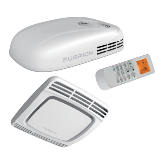
- Page 1 9K & 12K BTU ROOFTOP AIR CONDI- TIONER MODEL: FACR09SM-PS/FACR12SM-PS/FACTRCSM-PS LIPPERT NO.: 2021132274/2022107892/ 2021132281 USER MANUAL Product picture for reference only REV: 06.30.2022 CCD-0005745...
-
Page 2: Table Of Contents
Warning: This manual must be carefully read and understood before installation, adjustment, repair or maintenance. The equipment must be installed by qualified technicians. Transformation of this product is an extremely dangerous operation, which may lead to personal injury or property loss. Important: please keep this manual with the product. -
Page 3: Overview
CAUTION surface of other objects caused by the condensate of this product. Indicate a potentially dangerous situation, which may cause property damage. Main Parameters Installation Environment of Air FACR09SM-PS FACR12SM-PS Conditioner Rated cooling capacity 9000BTU 12000BTU Rated heating capacity 9500BTU 12500BTU ●... -
Page 4: Installation Instructions
INSTALLATION INSTRUCTIONS Precautions Please read the installation and operation instructions carefully before the installation and use of this product. The manufacturer will not be liable for any loss or injury caused by the noncompliance with this manual. ● The installation must comply with national electrical codes regulations or industry standards. -
Page 5: Preparation For Installation
Preparation for Installation the circuit breaker to the front position of the roof opening. The power line must be located on a separate 20A delay-action circuit breaker. Disassembly of Roof Vent ● Ensure that the wire extends into the roof opening by at Unscrew the screws and remove the vent. - Page 6 Placement after lifting Return air inlet of Front of RV air conditioner Pull down the wire harness Measure the of outdoor unit ceiling thickness 3. Measure the thickness from ceiling to roof to select the appropriate air duct sponge: – Air duct sponge (including 3 thickness specifications, i.e., 15mm, 30mm and 45mm) NOTE: Air duct sponge in the middle part is to keep...
-
Page 7: System Wiring
from the cable gland on the control box. The cable gland Chassis of the needs to be tightened to prevent the main power line Head direction outdoor unit of from being pulled and causing the connection to become air conditioner loose. - Page 8 Plugging of connecting wire of display lamp board Terminal of anti-freezing sensor of connecting main board Fixing frame of temperature Corresponding sensing head buckles Panel Installation Press the left and right buckles on the decorative panel at the same time to remove the decorative panel, as shown in the following figure: Left and right buckles on the decorative...
-
Page 9: Control Instructions
CONTROL INSTRUCTIONS Description of Remote Controller FUNCTION NO. BUTTON After power-on, the compressor will be turned on in a few Set up the air conditioner MODE minutes. operating mode Press the “MODE” button to switch various modes (Auto, FAN SPEED Set up the fan speed Cooling, Dry, Fan, and Heating), the system will confirm to enter the selected working mode after 2 seconds, and... - Page 10 Cooling mode Fan mode Press the ON/OFF button “ ”switch on Press the ON/OFF button “ ” switch on the air conditioner, it will run by memory the air conditioner, it will run by memory mode. mode. Press the MODE button, set up the Press the MODE button, set up the mode to fan “...
- Page 11 Auto mode Timer on function Press the ON/OFF button “ ”switch on the air conditioner, it will run by memory The air conditioner is switched off. mode. Press the TIME ON button “ ” set Press the MODE button, set up the up the time which the air conditioner mode to auto “...
-
Page 12: Installation And Replacement Of The Battery Of Remote Controller
Installation and Replacement of the Temperature and error code display: used to set the display of temperature, room temperature and error code. Battery of Remote Controller Power light: when the machine is started up, the power light will be on. When it’s shut down, the power light will go Open the battery cover: hold the handle of the battery out. -
Page 13: Troubleshooting
TROUBLESHOOTING ● If the air conditioning equipment cannot work normally, operating load of this product and that there is power please carry out inspection as follows to remove the supply. Check whether the mains voltage meets related faults: requirements (the operating voltage of air conditioner is ●... -
Page 14: Installation Exploded Drawing
INSTALLATION EXPLODED DRAWING Roof of VR Outdoor unit of air conditioner Air duct sponge Control box Fixing plate Long bolt Panel Screw Filter screen Decorative panel Display board CCD-0005745 Rev: 06-30-22 - 13 -... - Page 18 The contents of this manual are proprietary and copyright protected by Lippert. Lippert prohibits the copying or dissemination of portions of this manual unless prior written consent for an authorized Lippert representation has been provided. Any unauthorized use shall void any applicable warranty. The information contained in this manual is subject to change without notice and at the sole discretion of Lippert.
Need help?
Do you have a question about the FACR09SM-PS and is the answer not in the manual?
Questions and answers