Table of Contents
Advertisement
Quick Links
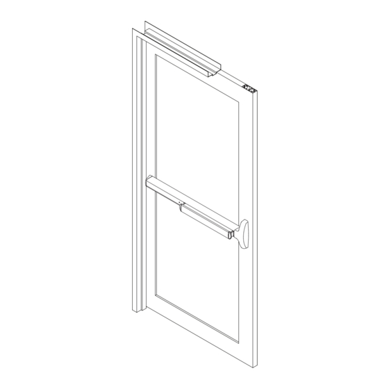
DX2 PC/FC
Grade 1, Concealed Vertical Rod Device (Panic or Fire Exit Hardware)
Installation Sequence
1. Carefully read and understand the installation instructions, templates and door
preparation BEFORE starting any installation or door preparation.
2. Prepare door for the installation of the exit device and any applicable trim.
3. Follow exit device and trim installation steps using supplied components and
mounting hardware.
4. Test function and performance after installing each component.
5. Perform a function and performance test at completion of installation.
Installation Instructions
WD-OD002 (666)
DX2PC-FC-INST
2021-10
Advertisement
Table of Contents

Subscribe to Our Youtube Channel
Related Manuals for Dorex DX2 PC


Summary of Contents for Dorex DX2 PC
- Page 1 DX2 PC/FC Installation Instructions Grade 1, Concealed Vertical Rod Device (Panic or Fire Exit Hardware) Installation Sequence 1. Carefully read and understand the installation instructions, templates and door preparation BEFORE starting any installation or door preparation. 2. Prepare door for the installation of the exit device and any applicable trim.
-
Page 2: Components Overview
COMPONENTS OVERVIEW Strike Strike Latch Screws Screws Top Latch Release Plunger Plunger Screws End Cap Screws End Cap Bracket End Cap Concealed Rod End Cap Bracket Screws Connector Rod Screws Cover Screws Support Bracket Screws Screws Support Bracket Bottom SPECIAL TOOLS REQUIRED Latch #8-32, #10-24, #1/4-20 Bottom Latch... -
Page 3: Screw Chart
SCREW CHART APPLICATION METAL SEX BOLTS WOOD 1/4-20 x 1-1/8" 2 PCS Trim mount or sex bolts 1/4-20 x 1-1/8" 2 PCS 1/4-20 x 1-11/16" Center Case Screws 2 PCS No.10-24 x 11/16" No.10-12 x 1-11/32" 2 PCS 2 PCS Center Case Screws No.10-24 x 1-11/32"... - Page 4 DOOR PREPARATION REFERENCE CHART IMPORTANT: Fire Exit Hardware is to be installed on Fire Doors bearing the marking “Fire Door to be equipped with Fire • Use supplied templates for field installations. TOP STRIKE Exit Hardware” Any retrofit or other field modification to •...
- Page 5 BACKSET INFORMATION BACKSET REFERENCE TABLE Backset and Door Stile width are determined by the applicable type of door and frame configuration and application Vertical of Device Backset Min. Stile Width Door Type Application Wood Door 1 ⁵⁄16" 2 ¹/8" - 2 ³/4" Door Stile 1 ¹/2"...
-
Page 6: Side View
03. PREPARE DOOR FOR DEVICE AND 04. DRILL TOP OF DOOR FOR RELEASE PLUNGER TOP & BOTTOM LATCHES Door Frame Stop Height ³⁄8 " Stop Height ¹⁄2" ¹¹⁄16" ⁵⁄8"-Std. ¹³⁄16" ³⁄4" ¹⁵⁄16" Measure "Stop Height of Door Frame" to decide "Dimension of A". - Page 7 07. INSTALL CONNECTORS 08. INSTALL TRIM (IF USING) AND SECURE DEVICE CENTER CASE TO DOOR Rod Screws Top Rod 1 ³/16" Minimum clearance Connector (with end cap removed). Door Stop If device is too long for door, (On Frame) see "CUT DEVICE" on page 12.
- Page 8 10. INSTALL ROD SIDE SCREWS 11. HANG DOOR AND INSTALL TOP STRIKE & RELEASE PLUNGER Retractor Support Strike Bracket Screws DXAS216 Strike See "FRAME PREPARATION" on page 9 for cut-out and holes. After preparing, install top strike into door frame and mount with two(2) strike screws.
- Page 9 ADJUST LATCHES AND SECURE TOP & BOTTOM LOCKING SCREWS 1. Depress push bar to retract the latch Figure 1 bolt and open the door. 2. Check top latch for HOLDBACK (Latchbolt stays retracted in latch case). (See Figure 1) 3. Loosen top locking screw. 4.
- Page 10 FLOOR PREPARATION FOR BOTTOM STRIKE STRIKE + EXIT DEVICE ROD INSIDE FACE INSIDE FACE OF DOOR OF DOOR ¹⁄4" ⁵⁄8" (6.4 mm) ⁷⁄16" 1" (11 mm) (16 mm) (25.4 mm) Floor DXAS227 1¹⁄8" ± ¹⁄4 " 1¹⁄2" (28.5 mm) LATCH Adjustment (38 mm) Floor cavity...
- Page 11 INSTALL FIRE BOLT NOTE: Fire rated exit device with Less Bottom Rod (LBR) application must use a FIRE BOLT Recess required if gap between door and frame is less than 1/8" (3 mm). #8-32 TAP 3 ³/4" minimum Auxiliary Fire Bolt DXAFL Strike Hole...
-
Page 12: Bottom View
DOGGING (PANIC EXIT DEVICES ONLY) DOGGING ACTIVATION CYLINDER DOGGING INSTALLATION If cylinder is not installed, remove cover plate and install cylinder with cam orientation as shown below. Flat Tool/ or Hex Key Cylinder Hinge Side BOTTOM VIEW Cover Plate Cylinder Key Cylinder Locating whasher...
Need help?
Do you have a question about the DX2 PC and is the answer not in the manual?
Questions and answers