Advertisement
Quick Links
DX KA
Alarm Exit Device
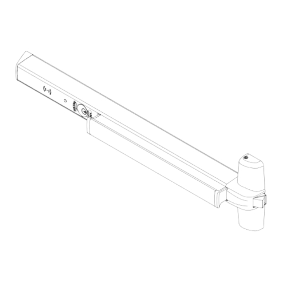
COMPONENTS:
Cover Plate
(Include Alarm Exit Module)
SPECIFICATIONS:
Voltage ..................................................... 12 to 24VDC,
Current ...................................................... 0.2A
Battery ....................................................... 9V
Normally open inputs ................................ External inhibit (EI)
NOTE : 1. The Alarm Exit Module requires an RX or LM switch mounted in the exit device.
2. Choose battery or remote power for usage.
3. Alarm Kit can be used for DX1 or DX2 FR, FV, FC, FM and FW models.
(DX1ALFR model shown)
9 Volt Battery
Cylinder Lock Nut
12 to 24VAC
Alarm Exit Device
EMERGENCY EXIT ONLY
PUSH TO OPEN ALARM WILL SOUND
(packed in cardboard tube)
1
Installation Instructions
Emergency Exit Sign
DX-KA3-INST 2020-06
WD-OD002(668)
Advertisement

Related Manuals for Dorex DX KA


Summary of Contents for Dorex DX KA
- Page 1 DX KA Installation Instructions Alarm Exit Device COMPONENTS: Alarm Exit Device (DX1ALFR model shown) EMERGENCY EXIT ONLY PUSH TO OPEN ALARM WILL SOUND Cover Plate 9 Volt Battery Cylinder Lock Nut Emergency Exit Sign (Include Alarm Exit Module) (packed in cardboard tube) SPECIFICATIONS: Voltage .............
- Page 2 01. COMPLETE WIRING (IF REQUIRED) 02. INSTALL CYLINDER AND BATTERY 1-1/4" Mortise Cylinder 5/16" 5/8" Diameter Drill 5/8"dia. wire access hole thru device side of door. 9 Volt Transmitting Battery Cylinder Lock Nut Thread cylinder lock nut onto mortise cylinder. Make sure to fasten down tight.
- Page 3 04. INSTALL COVER PLATE 05. INSTALL MOUNTING BRACKET AND END CAP End Cap Cover Plate Bracket Contacts External Inhibit (EI) End Cap Screws Anti-Rattle Clip Contacts RX or LM Switch End Cap Bracket Contacts Power End Cap Screws Supply Insert cover plate back into the mechanism case. After all wire connections are made and device checked for NOTE: Be careful not to pinch cable when sliding operation, install the end cap bracket, end cap and label .
- Page 4 OPERATION LED Indicator Mortise Cylinder 1. Insert the key into the cylinder and turn clockwise to arm unit. Rotate to initial position to remove key. 2. Arming time is of 15 seconds, during which the LED flashes green every 1.5 seconds. 3.
Need help?
Do you have a question about the DX KA and is the answer not in the manual?
Questions and answers