
Subscribe to Our Youtube Channel
Related Manuals for masosine SPS 100


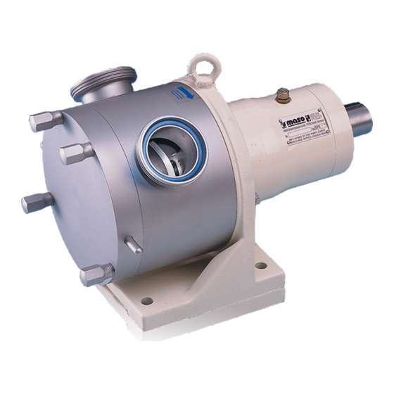
Summary of Contents for masosine SPS 100
-
Page 1: Table Of Contents
SPS Pump User Manual Contents 1 Declaration of conformity 2 Warranty 3 Information for returning pumps 4 Environment and disposal of waste 5 When you unpack your pump 6 Sinusoidal pumps - an overview 7 Safety notes 7.1 Obligation of the operating organisation 7.2 Organisational measures 7.3 Obligation of the operators 7.4 Personnel training... - Page 2 21.3 Adjusting dimension X in models with stainless steel power frame 22 Disassembly and assembly 22.1 Dismantling all models 22.2 Dismantling and assembling the SPS 100 22.3 Dismantling and assembling the SPS 200 22.4 Dismantling and assembling the SPS 250, SPS 300, SPS 400 and SPS 500 23 The static flushing device 23.1 SPS 100...
-
Page 3: Declaration Of Conformity
Name and address of the authorised documentation officer: Watson Marlow GmbH, Steinbeisstr. 3, 74360 Ilsfeld (Germany) Product : MasoSine Pump Type deignation : Certa, Certa Plus, SPS, MR, EcoSine The above-mentioned manufacturer declares on his own responsibility that the product /... -
Page 4: Warranty
MasoSine will not be liable for any loss, damage, or expense directly or indirectly related to or arising out of the use of its products, including damage or injury caused to other products, machinery, buildings, or property. -
Page 5: Information For Returning Pumps
(s) you return to MasoSine or its distributors. Failure to do so will cause delays. Please ensure that you email us this information and receive a RGA (Returned Goods Authorisation) before you despatch the product(s). A copy of the RGA form must be attached to the outside of the packaging containing the product(s). -
Page 6: When You Unpack Your Pump
SPS 100 SPS 200 SPS 250 SPS 300 SPS 400 SPS 500 • SPS 100, SPS 200, SPS 250, SPS 300, SPS 400 or SPS 500 sinusoidal pump, bare- shaft, with stainless steel or cast iron power frame m-SPS-en-08... - Page 7 • The technical datasheet identifying, describing and defining the pump • Operating instructions Optional items • Coupling • Coupling guard • Drive • Baseplate Optional special design • Flush systems • Guard master • Jacketing for heating and cooling Storage This product has an extended shelf life.
-
Page 8: Sinusoidal Pumps - An Overview
Sinusoidal pumps - an overview The functioning principle of MasoSine pumps is ingeniously simple. The pump consists of modular components. The sinusoidal rotor creates a chamber within the pump body four times per revolution, in which the pumped fluid is displaced. As a filled chamber rotates, it contracts, closes and discharges its contents. At the same time, the opposite chamber opens by the same fraction of a millimetre to draw in more fluid. -
Page 9: Safety Notes
Dangers when handling the machine The MasoSine pump is built according to state-of-the-art principles and the recognised safety engineering rules. Nevertheless, danger to life and limb of the user or third persons, or impairments to the machine or to other assets, can arise in its use. -
Page 10: Protective Devices
Watson-Marlow GmbH MasoSine Division. Replace machine parts which are not in perfect condition immediately. Use only original spare and wearing parts. Parts that are not obtained from MasoSine are not guaranteed to be designed and manufactured in compliance with load and safety requirements. -
Page 11: Limit Values For The Pump
After maintenance work is finished, check the safety devices are functioning. Bearings maintenance • The bearings of SPS 100 pumps must be renewed after running for the periods shown in the table below. 200 rpm 400 rpm... -
Page 12: Cleaning The Pump
Pumps needing repair, servicing, new bearings or other work on the power end must be returned to MasoSine for attention. Special training is available for users of SPS 200, SPS 250, SPS 300, SPS 400 and SPS 500 models. Please contact MasoSine for further information. -
Page 13: Safety Notes (Atex)
Application field “dust – or gas – explosive areas”. Zone classification MasoSine pumps can be used in explosive areas of zone 1 / 21. This corresponds to the category 2 G / D. It is expressly forbidden to use the pumps in zone 0. -
Page 14: Material Properties
Material properties The plastic parts fitted inside the pump react more to temperature changes than stainless steel parts. For this reason, the specified maximum fluid temperature for which the pump is designed must not be exceeded. This temperature is included in your purchase documents. If the specified temperature is exceeded, linear expansion may block the pump;... -
Page 15: Pump Specifications
Pump specifications Your pump carries a type plate on the bearing housing. It includes a serial number, which identifies the features of the product. The serial number also appears on the technical data sheet. An example name plate is shown below. (the abbreviations on the label are as follows: Pm=maximum pressure, max.=maximum speed, s/n=serial number) Standards 2006/42/EC: EC Machinery Directive... -
Page 16: Dimensions (In Millimetres)
Dimensions (in millimetres) SPS 100 m-SPS-en-08... - Page 17 SPS 200 pumps, dimensions Cast iron power frame Stainless steel power frame All critical dimensions of old and new power frame designs are the same, including mounting bolt holes. Both designs are interchangeable SPS 250 pumps, dimensions Stainless steel power frame m-SPS-en-08...
- Page 18 SPS 300 pumps, dimensions Cast iron power frame Stainless steel power frame All critical dimensions of old and new power frame designs are the same, including mounting bolt holes. Both designs are interchangeable m-SPS-en-08...
- Page 19 SPS 400 pumps, dimensions Cast iron power frame Stainless steel power frame All critical dimensions of old and new power frame designs are the same, including mounting bolt holes. Both designs are interchangeable m-SPS-en-08...
- Page 20 SPS 500 pumps, dimensions Stainless steel power frame Unit weights Weight of standard Pump weight, cast Pump weight, stainless steel baseplate power frame power frame Part no: 13.00kg 28lb 17.00kg 37lb 8oz KK-... 11oz Part no: 13.00kg 28lb 23.00kg 50lb 11oz 20.00kg 44lb 1oz KK-...
-
Page 21: Transport
Transport Choose the right means of transport according to the size of the pump and the drive. The pump must be suspended correctly for transport. If using a crane or fork-lift truck, the ropes or belts must be sufficiently dimensioned. If the pump is transported with a lift truck or fork-lift truck, note that the unit's centre point is not necessarily the centre of gravity. -
Page 22: Good Pump Installation Practice
Good pump installation practice The motor shaft and pump shaft connection must be guarded to protect the user from contact, when in use. Place the pump on a level surface Do not start the pump without a coupling guard to protect the user from contact. The mounting surface should be strong enough to support the pump. -
Page 23: Connection To The Piping
The user must ensure that a pressure rise above the pressure agreed in the purchase order and listed in the technical data sheet is not possible. MasoSine pumps normally run with such a low resonant frequency that no damage results. However, particularly when running with inverters, certain frequencies can cause inter- f erence vibrations which must be avoided. -
Page 24: Possible Pump Orientations
The pump can run for only a short time with the gate and the gate guide wrongly oriented, and it will not achieve more than 2 bar pressure. See "Disassembly and assembly" on page 38. SPS 100 is shown here. All models are similar. m-SPS-en-08... - Page 25 The gate and gate guide shown inverted to make clear the gate’s position within the guide for counter- clockwise rotor rotation The gate and gate guide oriented for counter-clockwise rotor rotation The gate and gate guide oriented for clockwise rotor rotation If the direction of rotation is reversed, change the rotation direction indicator arrows and mark the suction and pressure ports correspondingly.
-
Page 26: Connecting This Product To A Power Supply
(sensors, switches, pressure gauges, etc.). Fluid level MasoSine pumps must be primed before use. Before commissioning and during operation, the pump must be filled with fluid, with the fluid level above the rotor (see diagram). This can be done manually through a side channel of your system’s pipework, or by using a vacuum... -
Page 27: Flushing The Seal System
Flushing the seal system Flushing fluid at atmospheric pressure—usually water—flushes the area behind the seal system and prevents the product from hardening and damaging the seal system. If a static flushing device is fitted, the flushing fluid fills the area behind the seal. Cast iron power frame: If no static flushing device is fitted, adapt a fitting and a tube to the threads of the intake and outlet in the power frame (see diagram below;... -
Page 28: Cleaning And Sterilisation
Attention: Keep a minimum distance of 50cm (20 inches) from the pump while performing high-pressure cleaning. MasoSine SPS pumps may be cleaned in place. Please follow our CIP cleaning instructions—see below. Maintaining a clean process line is vital to maintain a high level of hygiene and no contamination of an end-product. -
Page 29: Steam-In-Place (Sip) For Masosine Products
17.4 Steam-in-place (SIP) for MasoSine products Steam sterilisation kills micro-organisms through the application of moist heat (saturated steam) under pressure without disassembly. • Sterilising the pump with standard equipment is possible up to 120C only at standstill. • The pressure should be high enough to ensure that the steam reaches all parts of the static pump through the existing clearances. -
Page 30: Heating And Cooling Option
Heating and cooling option Special versions of MasoSine SPS 100, SPS 200, SPS 250, SPS 300, SPS 400 and SPS 500 pumps can be heated or cooled to provide the correct temperature for your process—pumping chocolate or ice cream, for example—by passing fluid at the temperature required through crescent-shaped channels in the pump housing and the front housing. -
Page 31: Changing The Oil
Changing the oil 19.1 SPS 100 Every day before using your pump, check that there is enough grease in the storage chamber. Remove the vent at A and insert grease through the nipple at B until grease starts to come out at A. Refit the vent. -
Page 32: Troubleshooting
Troubleshooting Error Cause Remedy Direction of rotation not correct Check direction of rotation No wetting liquid in pump Fill pump with liquid Screw fastening not tight Check screw fastening Suction pipe too long Adapt suction pipe Suction pipe too narrow Adapt suction pipe Pump does not draw in... - Page 33 Error Cause Remedy Remove foreign body, Foreign body in the pump examine pump for damage Check electrical installation Power supply interrupted Pump is blocked and fuses, check drive Separate the coupling and Defect in the drive turn the pump by hand to confirm Change the wearing parts Solids in the pumped fluid...
-
Page 34: Adjusting The Shaft
It is important that dimension X is correct to achieve efficient pumping. Note: Dimension X in all pumps may be measured as below. However, the structure of the SPS 100 pump casing is different from other models (and not as shown here) and SPS 100 dimension X is adjusted differently. - Page 35 • If this dimension is not correct, continue disassembly (see "Disassembly and assembly" on page 38) until the face of the power frame is accessible (the SPS 300 and the SPS 200 pumps are shown here; the SPS 400 is similar). •...
-
Page 36: Adjusting Dimension X In Models With Stainless Steel Power Frame
+0.1 +0.1 +0.1 Note: SPS 100 pumps must be returned to MasoSine for dimension X adjustment. • Remove the front cover, the front support, the front liner, the rotor, the gate and the gate guide. See "Disassembly and assembly" on page 38. - Page 37 Picture 1 Picture 2 Picture 3 • If this dimension is not correct, use a wrench to loosen and remove the screws securing the bearing housing to the power frame (arrowed; the number of screws varies with pump model). (Picture 1). •...
-
Page 38: Disassembly And Assembly
It is important to ensure that the shaft cannot rotate while the shaft nut is removed. If necessary, it may conveniently be secured using a well-padded wrench on the shaft and the key or keyway. A blocking tool for the shaft is optionally available for easy opening of the locking screw: (SPS 100: TL-SP10-010-31). •... - Page 39 Removing the front liner and the front bushing • Pull the front liner to remove it. Note: You may find it convenient to turn the pump shaft and rotor a little to create space for your fingertips to grasp the top of the front liner. •...
- Page 40 Removing the rear liner • Pull the rear liner to remove it. Removing the mechanical seal and the static face • Remove the mechanical seal. You can now access the mechanical seal O-rings. • Remove the static face. You can now access the static face O-ring. Note: If the static face cannot be removed by hand, it can be removed with the sealing system (see "Removing the sealing system"...
- Page 41 The front and back bushing. They are identical Removing the sealing system Note: If your SPS 100 pump is fitted with a static flushing system, this must be removed before removing the sealing system. See "The static flushing device" on page 83. m-SPS-en-08...
- Page 42 Reverse the special tools and use the angled ends in the same way to apply further leverage to the end of the seal housing, until it is accessible within the pump chamber. Remove it. The two versions of the SPS 100 pump seal housing: left, where no static flushing system is fitted; right, where a...
- Page 43 This can be done using the special tools as pushers, or using a special cylindrical tool which is available from MasoSine. Note: If a static flushing device is to be fitted, align the threaded sockets on both sides of the seal housing vertically, so they are central to the top hole in the bearing housing.
- Page 44 Note: The mechanical seal has a lug on its inner surface which must be aligned with the shaft splines. SPS 100 pumps with a triple lip seal: fitting the distance piece •...
- Page 45 Fitting the rear liner—all SPS 100 pumps • Push the rear liner into position, pushing evenly at both ends so that it does not jam. The anti- rotation pins within the pump housing (arrowed) guarantee that the liner is properly positioned. The two liners are identical.
- Page 46 • Hold the rotor vane in the slot of the gate, with the larger diameter end of the rotor bush away from you. Position the rotor, the gate and the gate guide together. Push the assembly into position. The gate and gate guide slide freely into their channel; the splines within the rotor hub must be aligned with the shaft splines.
- Page 47 It is important to ensure that the shaft cannot rotate while the shaft nut is fitted. If necessary, it may conveniently be secured using a well-padded wrench on the shaft and the key or keyway. A blocking tool for the shaft is optionally available for easy opening of the locking screw: (SPS 100: TL-SP10-010-31). •...
-
Page 48: Dismantling And Assembling The Sps
22.3 Dismantling and assembling the SPS 200 Dismantling the SPS 200 Note: The pictures show a pump with a cast iron power frame. Dismantling models with stainless steel power frame is similar. For exceptions, see "Dismantling the pump housing— SPS 200 pumps with a stainless steel power frame and a single mechanical seal"... - Page 49 The front support may come off the shaft with the front cover, as pictured (PEEK support: top pictures; stainless steel support: lower pictures), or it may remain on the shaft. Note: the PEEK front support is breakable. • Remove the front support. You can now access the front cover O-ring (arrowed) in its groove in the front cover.
- Page 50 Removing the shaft locking screw It is important to ensure that the shaft cannot rotate while the shaft locking screw is removed. It may be convenient to secure it using a tommy bar or a spanner handle between the spider castellations on the drive shaft.
- Page 51 Removing the shaft nut It is important to ensure that the shaft cannot rotate while the shaft nut is removed. If the motor is fitted to the pump, its torque should be enough to secure the shaft. If it is not secure, uncouple the pump from the motor and secure the shaft using a tommy bar or a spanner handle between the spider castellations on the drive shaft.
- Page 52 Removing the rear liner and the backing ring—SPS 200 pumps with a single mechanical seal • Pull the rear liner to remove it. • The backing ring may remain on the shaft or it may come off the shaft with the rear liner. •...
- Page 53 Removing the dynamic ring holder—SPS 200 pumps with a single mechanical seal • Pull the dynamic ring holder to remove it. The dynamic ring holder m-SPS-en-08...
- Page 54 Dismantling the pump housing—SPS 200 pumps with a cast iron power frame and a single mechanical seal Note: See "Dismantling the pump housing—SPS 200 pumps with a stainless steel power frame and a single mechanical seal" on page 58 for dismantling the pump housing of a pump with a cast iron power frame.
- Page 55 Removing the seal and the static face—pumps with a single mechanical seal • Remove the mechanical seal from the rear of the pump housing. • Remove the static face from the mechanical seal. • You can now access the seal housing O-ring in its groove in the pump housing (arrowed above), and the two O-rings in the mechanical seal (arrowed below).
- Page 56 Removing the sealing system—SPS 200 pumps with a triple lip seal • Pull the seal housing fitted with the shaft sleeve to remove it. shaft sleeve lip seals seal housing • Remove the shaft sleeve from the seal housing. Removing the pump housing—SPS 200 pumps with a triple lip seal •...
- Page 57 Removing the distance ring—SPS 200 pumps with a triple lip seal • The distance ring is a loose fit in its channel on the face of the power frame. Use a tool such as a pair of long-nose pliers to grasp the distance ring where recesses have been machined in the face of the power frame and withdraw it.
- Page 58 Dismantling the pump housing—SPS 200 pumps with a stainless steel power frame and a single mechanical seal Note: See "Dismantling the pump housing—SPS 200 pumps with a cast iron power frame and a single mechanical seal" on page 54 for dismantling the pump housing of a pump with a cast iron power frame. •...
- Page 59 Fitting the static face and the seal—SPS 200 pumps with a single mechanical seal The mechanical seal The static face • Check that the seal housing O- ring is properly positioned in its groove in the pump housing (arrowed in bottom left picture), and that the two O-rings either side of the mechanical seal are properly positioned (arrowed above).
- Page 60 Fitting the pump housing—SPS 200 pumps with a cast iron frame and a single mechanical seal • Pass the pump housing, complete with mechanical seal and static face, over the shaft and position on the face of the power frame. The pump housing is heavy.
- Page 61 Fitting the dynamic ring holder—SPS 200 pumps with a single mechanical seal The dynamic ring holder • Push the dynamic ring holder over the pump shaft, narrow end first. The dynamic ring holder has an alignment lug inside it which must be aligned with the shaft splines. Fitting the backing ring and the rear liner—SPS 200 pumps with a single mechanical seal The backing ring •...
- Page 62 Fitting the distance ring—SPS 200 pumps with a triple lip seal The distance ring with radiused edge up • The distance ring is a loose fit in its channel on the face of the power frame. Position it with the radiused edge facing the power frame.
- Page 63 Note: The pump housing may be positioned in three orientations. See "Possible pump orientations" on page 24. The pump housing is heavy. • Fit the two 13mm screws (right-hand thread) and washers which secure the pump housing to the power frame. 10-2 assembly is shown here. Alternative screw positions (three of four arrowed) allow the pump housing to be positioned at 9-12 or 12-3 orientations.
- Page 64 Fitting the sealing system—SPS 200 pumps with a cast iron power frame and a triple lip seal seal housing shaft sleeve lip seals • Push the seal housing into the shaft sleeve. • Push the shaft sleeve fitted with the seal housing over the shaft and into position, the chamfered, lip-seal end of the shaft sleeve first.
- Page 65 • Push the shaft sleeve fitted with the seal housing over the shaft and into position, the chamfered, lip-seal end of the shaft sleeve first. The seal housing’s pins (arrowed) must be upward and central. The shaft sleeve is a tight push fit. Be sure to push it all the way home. The shaft sleeve has an alignment lug inside it (ringed) which must be aligned with the shaft splines.
- Page 66 Fitting the rotor, the gate and the gate guide The gate and gate guide Pressure Suction Suction Pressure side side side side The gate and The gate and gate guide gate guide oriented for oriented for counter- clockwise clockwise rotor rotation rotor rotation •...
- Page 67 Fitting the shaft nut—SPS 200 pumps The shaft nut It is important to ensure that the shaft cannot rotate while the shaft nut is fitted. It may conveniently be secured using a tommy bar or a spanner handle between the spider castellations on the drive shaft. Alternatively, a well-padded wrench can be used on the shaft and the key or keyway.
- Page 68 Fitting the front support The PEEK front support • Position the PEEK front support, castellations first, it its recess in the front cover (the side with slots must face the front cover). • Check that the front cover O-ring (arrowed) is in its groove in the front cover. Stainless steel front support Fitting the front cover •...
- Page 69 22.4 Dismantling and assembling the SPS 250, SPS 300, SPS 400 and SPS 500 Dismantling the SPS 250 SPS 300 SPS 400 and SPS 500 Note: The SPS 250, SPS 400 and the SPS 500 are similar. Note: The pictures show a pump with a cast iron power frame. Dismantling models with stainless steel power frame is similar.
- Page 70 Removing the shaft locking screw and the shaft nut It is important to ensure that the shaft cannot rotate while the shaft locking screw and the shaft nut are removed. It may be convenient to secure it using a well-padded wrench on the shaft and the key or keyway.
- Page 71 The locking screw The shaft nut The front support Removing the rotor, the gate and the gate guide • Note the orientation of the gate and the gate guide so that they can be refitted in the same orientation. Use two hands to remove the rotor, the gate and the gate guide together. •...
- Page 72 Removing the rear liner and the backing ring—pumps with a single mechanical seal • Pull the rear liner to remove it. • Remove the backing ring. The backing ring m-SPS-en-08...
- Page 73 Removing the dynamic ring holder—pumps with a single mechanical seal • Pull the dynamic ring holder to remove it. The dynamic ring holder Removing the pump housing—pumps with a single mechanical seal m-SPS-en-08...
- Page 74 • Guide the optional special cylindrical tool (arrowed: TL-SP21-002-50, TL-SP25-002-50, TL-SP40- 002-50 or TL-SP50-002-50 - available to order) over the shaft and push it home. This will give some protection to the shaft splines as the pump housing is removed. It is important not to damage the shaft while removing or installing the pump housing.
- Page 75 Dismantling the pump housing— pumps with a stainless steel power frame and a single mechanical seal Note: See page "Removing the pump housing—pumps with a single mechanical seal" on page 73 for dismantling the pump housing of a pump with a cast iron power frame. •...
- Page 76 Fitting the pump housing—pumps with a single mechanical seal Check that the seal housing O-ring is properly positioned in its groove in the pump housing (arrowed in bottom left picture, previous page). Guide the optional special cylindrical tool (TL-SP21-002-50, TL-SP25-002-50, TL-SP40-002-50 or TL-SP50- 002-50 - available to order) over the shaft and push it home.
- Page 77 • Position the static face in the mechanical seal. The static face has two recesses (arrowed) which must be correctly aligned with lugs (arrowed) either side of its seat. • Push the mechanical seal into the pump housing. Note: The mechanical seal is a tight push fit. Fitting the dynamic ring holder—pumps with a single mechanical seal The dynamic ring holder •...
- Page 78 Pumps with a single mechanical seal: fitting the backing ring and the rear liner The backing ring • Push the backing ring over the pump shaft and over the dynamic ring holder. The backing ring is reversible. • Push the rear liner into position below the backing ring. The anti-rotation pins within the pump housing (arrowed) guarantee that the liner is properly positioned.
- Page 79 Fitting the rotor, the gate and the gate guide The gate and gate guide Pressure Suction Suction Pressure side side side side The gate and The gate and gate guide orient- gate guide oriented for ed for counter- clockwise rotor clockwise rotor rotation rotation •...
- Page 80 Fitting the front support, the shaft nut and locking screw The PEEK front support The shaft nut The shaft locking screw It is important to ensure that the shaft cannot rotate while the shaft locking screw and the shaft nut are tightened.
- Page 81 Fitting the front liner • Push the front liner into position, pushing evenly at both ends so that it does not jam. The anti- rotation pins within the pump housing (arrowed) guarantee that the liner is properly positioned. The two liners are identical. Fitting the front cover •...
- Page 82 • Fit the flush ring. • Guide the optional special cylindrical tool (arrowed: TL-SP21-002-50, TL-SP25-002-50, TL-SP40- 002-50 or TL-SP50-002-50 - available to order) over the shaft and push it home. This will give some protection to the shaft splines as the pump housing is fitted. It is important not to damage the shaft while removing or installing the pump housing.
-
Page 83: The Static Flushing Device
The sight glass and the sight glass connection piece • The static flushing device can be fitted only to a SPS 100 pump with a pump seal housing which is tapped to take it (arrowed). See also "Assembling the SPS 100" on page 43. •... - Page 84 The bent outlet connection piece The bent outlet • Use a 17mm spanner to tighten it. • Use a 13mm spanner to remove the bolts, washers and spacers securing the baseplate. See "Changing the pump orientation" on page 24. • Check that the O-rings (arrowed) are in place on the bent outlet. Fit the bent outlet connection piece and the bent outlet through the bottom hole in the bearing housing in the same way.
-
Page 85: Sps 200, Sps 300, Sps 400 And Sps
Removing the static flushing device—SPS 100 pumps Note: The flushing device (if fitted) must be emptied and removed before dismantling the pump. • To remove the static flushing device, pour the flushing fluid from the sight glass, and reverse the sequence of operations described above. - Page 86 Removing the static flushing device—SPS 200, SPS 300 and SPS 400 pumps with cast iron power frame Note: The flushing device (if fitted) must be emptied and removed before dismantling the pump. • Use a 19mm spanner to loosen the retaining nut holding the bent outlet in position (arrowed) enough to allow the bent outlet to be lowered into a horizontal position.
- Page 87 Fitting a flush ring with flush connections—SPS 200, SPS 250, SPS 300, SPS 400 and SPS 500 pumps with stainless steel power frame • Pass the tube through the space in the power frame. Connect it from the back to the dynamic flush system.
- Page 88 Fitting a flush ring with a static flush device—SPS 200, SPS 250, SPS 300, SPS 400 and SPS 500 pumps with stainless steel power frame • Install the flush ring without the bent outlet. • Fit the bent outlet to the connection on the back of the power end. •...
-
Page 89: Tightening Torques
Tightening torques SPS 100 Adjoining parts Screw type Torque Bearing housing cover—bearing M8 DIN 912 10Nm / 7 lb-ft housing Feet M8 DIN 931 25Nm / 18.5 lb-ft Grease nipple M6 DIN 71412 10Nm / 7 lb-ft Shaft—shaft nut SW17 100Nm / 74 lb-ft Front cover—cap nut... - Page 90 Adjoining parts Screw type Torque Shaft—locking screw SW42, LEFT-HAND THREAD 95Nm / 70 lb-ft Front cover—cap nut SW22 45Nm / 33 lb-ft SPS 400 Adjoining parts Screw type Torque Bearing housing cover—bearing M6 A2 70 DIN 931 7Nm / 5 lb-ft housing Power frame—bearing housing M12 A2 70 DIN 931...
-
Page 91: Parts Lists
Where __ appears instead of an alphanumeric code in positions xxx and zz, select from the tables which follow. xxx: Pump type Code Pump SPS 100 SPS 200 SPS 250 SPS 300 SPS 400 SPS 500... -
Page 92: Pumps
25.1 Pumps SPS 100 m-SPS-en-08... - Page 93 Parts list for SPS 100 Number Quantity Part code Item S10-0100-10 Rotor S10-0200-10 Front Cover S10-0300-10 Pump housing S10-0400-49 Gate, MASOTRONIC-2070-WR S10-0400-46 Gate, MASOTRONIC-2051-MW S10-0700-10 Gate Guide S10-1097-50 Liner oversized, MASOTRONIC-2800-PO S10-1097-62 Liner oversized, MASOTRONIC-2080-PK S10-1094-10 Shaft Nut Front Support...
- Page 94 Number Quantity Part code Item S10-1109-12 Spacer Ring, Inboard Oil Seal 80-3600-12 Nameplate 80-3605-12 Grooved Pin Integral with pump housing. Nozzles (on request) Type depends on customer choice S20-1600-12 Front Cover Nut S20-1601-12 Washer, Front Cover Nut S10-0029-12 Studs S25-0301-10 Taper Pin S10-0250-12 Front Cover Pin...
- Page 95 SPS 200 with cast iron power frame m-SPS-en-08...
- Page 96 Parts list for SPS 200 with cast iron power frame Number Quantity Part code Item S20-1600-12 Cap Nut S20-0200-10 Front Cover S20-0100-10 Rotor S20-0300-10 Pump Housing S20-2300-80 Lip Seal, NBR S25-3900-25 Lifting Eye Bolt S20-2100-33 Seal, Copper S20-2200-12 Cap Screw S20-2400-25 Bearing, Tapered Roller S20-1401-30...
- Page 97 Number Quantity Part code Item S20-1753-80 O-Ring, Power Frame, NBR S20-1750-80 O-Ring, Pump Housing, NBR S20-1750-82 O-Ring, Pump Housing, EPDM S20-1750-84 O-Ring, Pump Housing, FPM/FKM S20-1751-80 O-Ring, Rotor, NBR S20-1751-82 O-Ring, Rotor, EPDM S20-1751-84 O-Ring, Rotor, FPM / FKM S20-1200-50 Liners, MASOTRONIC-2800-PO S20-1200-62 Liners, MASOTRONIC-2080-PK...
- Page 98 SPS 200 with stainless steel power frame m-SPS-en-08...
- Page 99 Parts list for SPS 200 with stainless steel power frame Number Quantity Part code Item S20-1600-12 Cap Nut S20-0200-10 Front Cover S20-0100-10 Rotor S20-0300-10 Pump Housing S20-2320-80 Lip seal, inboard S20-2220-25 Cap Screw S20-2420-25 Tapered Roller Bearing S20-1421-30 Shim-Ring S20-1420-12 Bearing Housing S20-6000-50 Vent Valve...
- Page 100 Number Quantity Part code Item S20-1751-80 O-Ring, Rotor, NBR S20-1751-82 O-Ring, Rotor, EPDM S20-1751-84 O-Ring, Rotor, FPM / FKM S20-1200-50 Liners, MASOTRONIC-2800-PO S20-1200-62 Liners, MASOTRONIC-2080-PK S20-1200-63 Liners, MASOTRONIC-2681-HT S20-1701-80 O-Ring, Front Cover, NBR S20-1701-82 O-Ring, Front Cover, EPDM S20-1701-84 O-Ring, Front Cover, FPM / FKM S20-1800-12 Front Cover Studs S20-5010-12...
- Page 101 SPS 250 with stainless steel power frame m-SPS-en-08...
- Page 102 Parts list for SPS 250 with stainless steel power frame Number Quantity Part code Item S21-1600-12 Cap Nut S21-0200-10 Front Cover S21-0100-10 Rotor S21-0300-10 Pump Housing S21-2320-80 Lip seal, inboard S21-3920-12 Lifting bolt M12 S21-2220-12 Cap Screw S21-2420-25 Bearing, Tapered Roller S21-1421-30 Shim Ring S21-1420-12...
- Page 103 Number Quantity Part code Item S21-1750-80 O-Ring, Pump Housing, NBR S21-1750-82 O-Ring, Pump Housing, EPDM S21-1750-84 O-Ring,Pump Housing,FPM/FKM S21-1751-80 O-Ring, Rotor, NBR S21-1751-82 O-Ring, Rotor, EPDM S21-1751-84 O-Ring, Rotor, FPM / FKM S21-1200-50 Liners, MASOTRONIC-2800-PO S21-1200-62 Liners, MASOTRONIC-2080-PK S21-1200-63 Liners, MASOTRONIC-2681-HT S21-1701-80 O-Ring, Front Cover, NBR S21-1701-82...
- Page 104 SPS 300 with cast iron power frame m-SPS-en-08...
- Page 105 Parts list for SPS 300 with cast iron power frame Number Quantity Part code Item S25-1600-12 Cap Nut S25-0200-10 Front Cover S25-0100-10 Rotor S25-0300-10 Pump Housing S25-2300-80 Lip Seal, NBR S25-3900-25 Lifting Eye Bolt S25-2100-33 Seal, Copper S25-2200-12 Cap Screw S25-2400-25 Bearing, Tapered Roller S25-1401-30...
- Page 106 Number Quantity Part code Item S25-1753-80 O-Ring, Power Frame, NBR S25-1753-82 O-Ring, Power Frame, EPDM S25-1753-84 O-Ring, Power Frame, FPM/FKM S25-1750-80 O-Ring, Pump Housing, NBR S25-1750-82 O-Ring, Pump Housing, EPDM S25-1750-84 O-Ring,Pump Housing,FPM/FKM S25-1751-80 O-Ring, Rotor, NBR S25-1751-82 O-Ring, Rotor, EPDM S25-1751-84 O-Ring, Rotor, FPM / FKM S25-1200-50...
- Page 107 SPS 300 with stainless steel power frame m-SPS-en-08...
- Page 108 Parts list for SPS 300 with stainless steel power frame Number Quantity Part code Item S25-1600-12 Cap Nut S25-0200-10 Front Cover S25-0100-10 Rotor S25-0300-10 Pump Housing S25-2320-80 Lip seal, inboard S25-3920-12 Lifting bolt M12 S25-2220-12 Cap Screw S25-2420-25 Bearing, Tapered Roller S25-1421-30 Shim Ring S25-1420-12...
- Page 109 Number Quantity Part code Item S25-1750-80 O-Ring, Pump Housing, NBR S25-1750-82 O-Ring, Pump Housing, EPDM S25-1750-84 O-Ring,Pump Housing,FPM/FKM S25-1751-80 O-Ring, Rotor, NBR S25-1751-82 O-Ring, Rotor, EPDM S25-1751-84 O-Ring, Rotor, FPM / FKM S25-1200-50 Liners, MASOTRONIC-2800-PO S25-1200-62 Liners, MASOTRONIC-2080-PK S25-1200-63 Liners, MASOTRONIC-2681-HT S25-1701-80 O-Ring, Front Cover, NBR S25-1701-82...
- Page 110 SPS 400 with cast iron frame m-SPS-en-08...
- Page 111 Parts list for SPS 400 with cast iron frame Number Quantity Part code Item S40-1600-12 Cap Nut S40-0200-10 Front Cover S40-0100-10 Rotor S40-0300-10 Pump Housing S40-2300-80 Lip Seal, NBR S40-3900-25 Lifting Eye Bolt S40-2100-33 Seal, Copper S40-2200-12 Cap Screw S40-2400-25 Bearing, Tapered Roller S40-1401-30 Shim-Ring...
- Page 112 Number Quantity Part code Item S40-1753-80 O-Ring, Power Frame, NBR S40-1753-82 O-Ring, Power Frame, EPDM S40-1753-84 O-Ring, Power Frame, FPM/FKM S40-1750-80 O-Ring, Pump Housing, NBR S40-1750-82 O-Ring, Pump Housing, EPDM S40-1750-84 O-Ring,Pump Housing,FPM/FKM S40-1751-80 O-Ring, Rotor, NBR S40-1751-82 O-Ring, Rotor, EPDM S40-1751-84 O-Ring, Rotor, FPM / FKM S40-1200-50...
- Page 113 SPS 400 with stainless steel frame m-SPS-en-08...
- Page 114 Parts list for SPS 400 with stainless steel frame Number Quantity Part code Item S40-1600-12 Cap Nut S40-0200-10 Front Cover S40-0100-10 Rotor S40-0300-10 Pump Housing S40-2320-80 Lip Seal, NBR S40-3920-12 Lifting Eye Bolt S40-2220-12 Cap Screw S40-2420-25 Bearing, Tapered Roller S40-1421-30 Shim-Ring S40-1420-12...
- Page 115 Number Quantity Part code Item S40-1750-80 O-Ring, Pump Housing, NBR S40-1750-82 O-Ring, Pump Housing, EPDM S40-1750-84 O-Ring,Pump Housing,FPM/FKM S40-1751-80 O-Ring, Rotor, NBR S40-1751-82 O-Ring, Rotor, EPDM S40-1751-84 O-Ring, Rotor, FPM / FKM S40-1200-50 Liners. MASOTRONIC-2800-PO S40-1200-62 Liners. MASOTRONIC-2080-PK S40-1200-63 Liners. MASOTRONIC-2681-HT S40-1701-80 O-Ring, Front Cover, NBR S40-1701-82...
- Page 116 SPS 500 with stainless steel power frame m-SPS-en-08...
- Page 117 Parts list for SPS 500 with stainless steel power frame Number Quantity Part code Item S50-1600-12 Cap Nut S50-0200-10 Front Cover S50-0100-10 Rotor S50-0300-10 Pump Housing S50-2320-80 Lip seal, inboard S50-3920-12 Lifting bolt M12 S50-2220-12 Cap Screw S50-2420-25 Bearing, Tapered Roller S50-1421-30 Shim Ring S50-1420-12...
- Page 118 Number Quantity Part code Item S50-1750-80 O-Ring, Pump Housing, NBR S50-1750-82 O-Ring, Pump Housing, EPDM S50-1750-84 O-Ring,Pump Housing,FPM/FKM S50-1751-80 O-Ring, Rotor, NBR S50-1751-82 O-Ring, Rotor, EPDM S50-1751-84 O-Ring, Rotor, FPM / FKM S50-1200-50 Liners, MASOTRONIC-2800-PO S50-1200-62 Liners, MASOTRONIC-2080-PK S50-1200-63 Liners, MASOTRONIC-2681-HT S50-1701-80 O-Ring, Front Cover, NBR S50-1701-82...
-
Page 119: Seals
95PT: SiC / SiC and PTFE Material of product contact items 97: SiC / CA and FKM 97EP: SiC / CA and EPDM 97NB: SiC / CA and NBR 97PT: SiC / CA and PTFE Mechanical seal, single, SPS 100 m-SPS-en-08... - Page 120 Number Quantity Part code Item S10-0011-80 O-Ring, NBR S10-0011-82 O-Ring, EPDM S10-0011-84 O-Ring, FPM / FKM S10-0037-80 Lip Seal, NBR S10-0042-10 Stationary Ring Holder S10-0043-10 Dynamic Ring Holder S10-0045-41 Stationary Seal Face, SiC S10-0046-41 Rotating Seal Face, SiC S10-0047-84 O-ring, FPM / FKM S10-0047-82 O-ring, EPDM S10-0048-10...
- Page 121 Number Quantity Part code Item 020P572.1420A1 Spring S20-5230-10 Spring support S20-5222-10 Straight pin S20-5245-41 Static surface, SiC S20-5245-66 Static surface, C S20-5246-80 O-ring, NBR S20-5246-82 O-ring, EPDM S20-5246-84 O-ring, FPM / FKM S20-5200-10 Static ring holder S20-5240-80 Cup with dynamic surface, SiC - NBR S20-5240-82 Cup with dynamic surface, SiC - EPDM S20-5240-84...
- Page 122 SPS 250 (S21-064#-##) Number Quantity Part code Item S21-5223-12 Snap ring S21-5220-10 Spring holder 020P572.1420A1 Set screw S21-5230-10 Spring support S21-5245-41 Static surface, SiC S21-5245-66 Static surface, C S21-5246-80 O-ring, NBR S21-5246-82 O-ring, EPDM S21-5246-84 O-ring, FPM / FKM S21-5200-10 Static ring holder S21-5240-80 Cup with dynamic surface, SiC - NBR...
- Page 123 SPS 300 (S25-064#-##) Number Quantity Part code Item S25-5210-10 Dynamic ring holder S25-5223-12 Snap ring S25-5220-10 Spring holder 020P572.1420A1 Spring S25-5230-10 Spring support S25-5222-10 Straight pin S25-5245-41 Static surface, SiC S25-5245-66 Static surface, C S25-5246-80 O-ring, NBR S25-5246-82 O-ring, EPDM S25-5246-84 O-ring, FPM / FKM S25-5200-10 Static ring holder...
- Page 124 SPS 400 (S40-064#-##) Number Quantity Part code Item S40-5240-80 Cup with dynamic surface, SiC - NBR S40-5240-82 Cup with dynamic surface, SiC - EPDM S40-5240-84 Cup with dynamic surface, SiC - FPM/FKM S40-5250-50 Backing ring, polyamide S40-5250-55 Backing ring, PPS S40-5250-62 Backing ring, PEEK S40-8505-80...
- Page 125 Lip seal assembly, triple lip seal system, SPS 100 SPS 100 (S10-0517-10##) Number Quantity Part code Item S10-0011-80 O-Ring, NBR S10-0011-82 O-Ring, EPDM S10-0011-84 O-Ring, FPM / FKM S10-0501-80 Lip Seal, NBR S10-1194-10 Spacer, Lip Seal S10-1116-10 Lip Seal Housing...
- Page 126 Lip seal assembly, triple lip seal system, SPS 200 SPS 200 (S20-0517-50## / -62## / -66##) Number Quantity Part code Item S20-0513-10 Distance ring S20-0610-10 Shaft sleeve S20-0510-10 Seal housing, 1.4404 S20-0510-62 Seal housing, Peek S20-0510-66 Seal housing, carbon S20-0510-50 Seal housing, polyamide S20-5310-10 Support ring...
- Page 127 Lip seal assembly, triple lip seal system, SPS 200 with stainless steel housing SPS 200 (S20-0517-10##) Number Quantity Part code Item S20-0513-10 Distance ring S20-0610-10 Shaft sleeve S20-0510-10 Seal housing, 1.4404 S20-0510-62 Seal housing, Peek S20-0510-66 Seal housing, carbon S20-0510-50 Seal housing, polyamide S20-0503-10 Support ring...
- Page 128 Lip seal assembly, triple lip seal system, SP250, SP300, SP400 and SP500 SPS 250 (S21-0517-10##) Number Quantity Part code Item 025P374.2800A1 Insert Polyamide 025P374.2080A1 Insert Peek 025P374.2090A1 Insert Peek Nature S21-0610-10 Shaft sleeve S21-0510-10 Seal housing S21-5310-10 Support ring S21-0501-80 Lip seal, NBR S21-0501-84 Lip seal, FPM / FKM...
-
Page 129: Front Support Versions
SPS 400 (S40-0517-10##) Number Quantity Part code Item S40-0610-10 Shaft sleeve S40-0510-10 Seal housing S40-5310-10 Support ring S40-0501-80 Lip seal, NBR S40-0501-84 Lip seal, FPM / FKM SPS 500 (S50-0517-10##) Number Quantity Part code Item 050P374.2800A1 Insert Polyamide 050P374.2080A1 Insert Peek 050P374.2090A1 Insert Peek Nature S50-0610-10... - Page 130 SPS 200 front support assembly (S20-0950-##) Number Quantity Part code Item S20-0800-10 Shaft nut S20-1752-80 O-ring, NBR S20-1752-82 O-ring, EPDM S20-1752-84 O-ring, FPM / FKM S20-1100-10 Locking screw S20-0900-10 Front support S20-0900-50 Front support polyamide S20-0900-55 Front support, PPS S20-0900-62 Front support, PEEK S20-0900-66 Front support, carbon...
- Page 131 SPS 250 front support assembly (S21-0950-10##) Number Quantity Part code Item 025P374.2800A1 Insert Polyamide 025P374.2080A1 Insert Peek 025P374.2090A1 Insert Peek nature S21-0900-10 Front support SPS 300 front support assembly (S30-0950-10##) Number Quantity Part code Item S25-0800-10 Shaft nut S25-1752-80 O-ring, NBR S25-1752-82 O-ring, EPDM S25-1752-84...
- Page 132 SP250, SP300, SP400 and SP500, dynamic front support SPS 250 front support assembly (S21-0950-##) Number Quantity Part code Item S21-0820-10 Shaft nut S21-1752-80 O-ring, NBR S21-1752-82 O-ring, EPDM S21-1752-84 O-ring, FPM / FKM S21-1100-10 Locking screw S21-0960-55 Front support, PPS S21-0960-62 Front support, PEEK SPS 300 front support assembly (S25-0950-##)
-
Page 133: Sealing/Distance Ring Version
SPS 400 front support assembly (S40-0950-##) Number Quantity Part code Item S40-0820-10 Shaft nut S40-1752-80 O-ring, NBR S40-1752-82 O-ring, EPDM S40-1752-84 O-ring, FPM / FKM S40-1100-10 Locking screw S40-0960-55 Front support, PPS S40-0960-62 Front support, PEEK SPS 500 front support assembly (S50-0950-##) Number Quantity Part code... - Page 134 SPS 200 (S20-1326-10) Number/Letter Part code Item S20-2300-80 Lip seal S20-8500-80 O-Ring SPS 250, SPS 300, SPS 400, SPS 500 Number/Letter Part code Item S__-1328-10 Distance ring S__-1755-80 O-ring S__-2321-80 Lip seal 80-0010-34 Flushing port 80-6005-10 Bushing 80-6004-10 Elbow 90 degrees m-SPS-en-08...
-
Page 135: The Static Flushing Device
25.5 The static flushing device With cast iron power frame SPS 200 Letter Part code Item 80-0014-95 Sight glass 80-0011-10 Connection piece 22-0178-10 Flushing pipe, long SPS 250, SPS 300, SPS 400, SPS 500 Letter Part code Item 80-0015-95 Sight glass 80-0012-10 Connection piece __-0178-10... - Page 136 With stainless steel power frame SPS 200 (S20-1327-10) Number/Letter Part code Item 80-0014-95 Glass for static flush-system 80-0012-10 Adapter/pipe fitting S20-0173-10 Flush pipe S20-1328-10 Distance ring S20-9001-10 Hexagon reducing nipple S20-9002-10 Elbow 90° S20-9003-10 Elbow 80-6005-10 Bushing 80-6009-10 Double nipple S20-1755-80 O-ring S20-0513-30...
-
Page 137: Available Wearing Kits
Sxx-1751-xx O-Ring, Rotor Sxx-1752-xx O-Ring locking screw Sxx-8505-xx O-Ring (only S21 up to S50) Mechanical seal wearing kit product side (for atmospheric side contact MasoSine) Part code Item S##-0660-95 Wearing Kit Mechanical Seal Product Side SiC/SiC-FKM S##-0660-95EP Wearing Kit Mechanical Seal Product Side SiC/CA-EPDM... - Page 138 Mechanical seal wearing kit product side (for atmospheric side contact MasoSine) Part code Item S##-0660-97 Wearing Kit Mechanical Seal Product Side SiC/SiC-FKM S##-0660-97EP Wearing Kit Mechanical Seal Product Side SiC/CA-EPDM m-SPS-en-08...
-
Page 139: Trademarks
Trademarks SPS and MasoSine are trademarks of Watson-Marlow Limited. Disclaimers The information contained in this document is believed to be correct but Watson-Marlow Limited Fluid Technology Group accepts no liability for any errors it contains and reserves the right to alter specifications without notice.
Need help?
Do you have a question about the SPS 100 and is the answer not in the manual?
Questions and answers