
Subscribe to Our Youtube Channel
Related Manuals for masosine Certa Plus


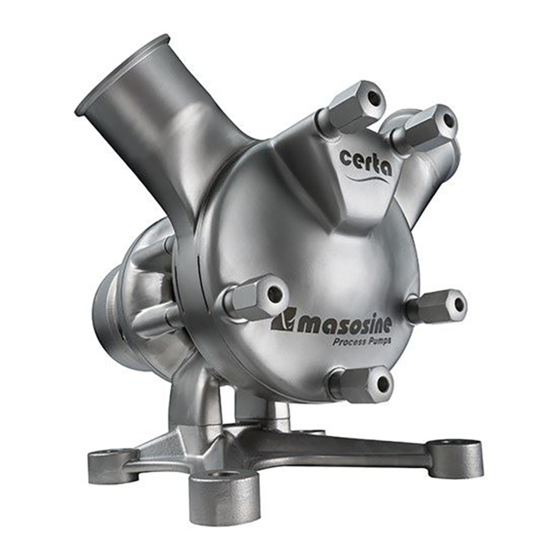
Summary of Contents for masosine Certa Plus
-
Page 1: Table Of Contents
Certa Plus Pump User Manual Contents 1 Declaration of conformity 2 Warranty 3 Intended use 4 How to handle stainless steel and other materials 5 Information for returning pumps 6 Environment and disposal of waste 7 When you unpack your pump... - Page 2 21.4 Flush ring 21.5 Atmospheric side of double mechanical seal 21.6 Static flush system 21.7 Dynamic flush system 21.8 Tools 22 Available wearing kits 23 Location of lot number on Certa Plus Parts 24 Trademarks 25 Disclaimers 26 Publication history m-certa-plus-en-02...
-
Page 3: Declaration Of Conformity
Watson Marlow GmbH, Steinbeisstr. 3, 74360 Ilsfeld (Germany) Product : MasoSine Pump : Certa, Certa Plus, SPS Type designation The above-mentioned manufacturer declares on his own responsibility that the product / machine conforms to all regulations of this EC directive:... -
Page 4: Warranty
This warranty shall not affect the warranty of the gear, motor or any other component which is not manufactured by MasoSine. MasoSine will not be liable for any loss, damage, or expense directly or indirectly related to or arising out of the use of its products, including damage or injury caused to other products, machinery, buildings, or property. -
Page 5: How To Handle Stainless Steel And Other Materials
(s) you return to MasoSine or its distributors. Failure to do so will cause delays. Please ensure that you email us this information and receive a RGA (Returned Goods Authorisation) before you despatch the product(s). A copy of the RGA form must be attached to the outside of the packaging containing the product(s). -
Page 6: When You Unpack Your Pump
Check that all components are present. Inspect components for damage in transit. If anything is missing or damaged, contact your distributor immediately. Components supplied MasoSine Certa Plus series sinusoidal pump, bare shaft The technical datasheet identifying, describing and defining the pump... -
Page 7: Obligation Of The Operating Organisation
Dangers when handling the machine The MasoSine pump is built according to state-of-the-art principles and the recognised safety engineering rules. Nevertheless, danger to life and limb of the user or third persons, or impairments to the machine or to other assets, can arise in its use. -
Page 8: Special Danger Points
Watson-Marlow GmbH MasoSine Division. Replace machine parts which are not in perfect condition immediately. Use only original spare and wearing parts. Parts that are not obtained from MasoSine are not guaranteed to be designed and manufactured in compliance with load and safety requirements. -
Page 9: Limit Values For The Pump
Pumps needing repair, servicing, new bearings or other work on the power end must be returned to MasoSine for attention. Special training is available. Please contact MasoSine for further information. -
Page 10: Cleaning The Pump
Mechanical seal Operator Check for leaks Expert In case of leakage: - Determine the degree of leakage - Consult Watson-Marlow MasoSine - Replace the wearing parts Elastomeric seals Operator Check for leaks (e.g. pump housing) Expert In case of leakage:... -
Page 11: Pump Specifications
Pump specifications Your pump carries a name plate on the bearing housing. It includes a serial number, which identifies the features of the product. The serial number also appears on the technical datasheet. An example name plate is shown below. (the abbreviations on the label are as follows: Pm=maximum pressure, max.=maximum speed, s/n=serial number) 10.1 Standards See "Declaration of conformity"... -
Page 12: Dimensions
10.2 Dimensions Dimensions in millimetres: Nozzles Foot Model P100 Ø12 Ø28 P200 99.5 Ø12 167.5 81.5 298.5 109.5 Ø28 P250 191.5 138.5 11.5 Ø17 Ø28 P300 237.5 152.5 17.5 Ø20 455.5 Ø50 53.5 P400 323.5 266.5 Ø21 513.5 292.5 Ø50 53.5 Dimensions in inches: Nozzles... -
Page 13: Transport
Transport Choose the right means of transport according to the size of the pump and the drive. The pump must be suspended correctly for transport. If using a crane or fork-lift truck, the ropes or belts must be sufficiently dimensioned. If the pump is transported with a lift truck or fork-lift truck, note that the unit's centre point is not necessarily the centre of gravity. -
Page 14: Good Pump Installation Practice
Good pump installation practice The motor shaft and pump shaft connection must be guarded to protect the user from contact, when in use. Place the pump on a level surface Do not start the pump without a coupling guard to protect the user from contact. The mounting surface should be strong enough to support the pump. -
Page 15: Connection To The Piping
The user must ensure that a pressure rise above the pressure agreed in the purchase order and listed in the technical data sheet is not possible. MasoSine pumps normally run with such a low resonant frequency that no damage results. However, particularly when running with inverters, certain frequencies can cause interference vibrations which must be avoided. -
Page 16: Cavitation
12.3 Cavitation Cavitation is a problem in certain devices where fluid interacts with a moving surface. It can occasionally occur in sinusoidal pumps. Where a surface moves through a fluid, low pressure areas are formed on the surface. The faster the surface moves, the lower the pressure around it can become. -
Page 17: Possible Pump Orientations
12.4 Possible pump orientations The pump can be positioned in one of eight orientations, and can rotate clockwise or counter-clockwise. 10-02 12-03 02-04 * 03-06 04-08 06-09 08-10 * 09-12 Unless you specify otherwise when ordering, the pump is delivered in position 10-02. Special customised nozzle orientations are possible. -
Page 18: Start-Up And Operation
MasoSine for further information. The need to prime can be avoided by leaving product in the pump after it is stopped; by leaving CIP or SIP fluid in the pump after cleaning. -
Page 19: Flushing The Seal System
Flushing the seal system In order to prevent a dry run and to ensure a proper working sealing system a seal flush is recommended. Flushing fluid at atmospheric pressure—usually water—flushes the area behind the seal system and prevents the product from hardening and damaging the seal system. If a static flushing device is fitted, the flushing fluid fills the area behind the seal. -
Page 20: Static Flushing Device
Fitting the static flushing device The static flushing device can be fitted to a Certa Plus pump with a flush ring or a double mechanical seal. See also "Assembling the pump head" on page 34. The connection with the vent pipe must be connected to the highest flush port. -
Page 21: Cleaning And Sterilisation
Attention: Keep a minimum distance of 50cm (20 inches) from the pump while performing high-pressure cleaning. MasoSine Certa Plus series pumps are designed to be cleaned in place. Please follow our CIP cleaning instructions below. Maintaining a clean process line is vital to maintaining a high level of hygiene and no contamination of the end-product. - Page 22 CIP. In this case a manual cleaning procedure is recommended. Determine the pump cleaning schedule on-site for materials being processed and plant maintenance schedule. Principally, MasoSine Certa Plus series pumps do not require manual cleaning if CIP (clean-in- place) is performed after operation.
-
Page 23: Changing The Oil
Changing the oil Every day before using your pump, check the oil viewing glass at B in the bearing housing for damage and to confirm that there is enough oil in the end shield. The oil should reach the middle of the glass. Check that the drain plug C is in place and fully tightened. -
Page 24: Heating And Cooling Option
Heating and cooling option Special versions of MasoSine P100, P200, P250, P300 and P400 pumps can be heated or cooled to maintain the required product temperature within the pump—pumping chocolate or ice cream, for example—by passing fluid at the temperature required through crescent-shaped channels in the pump housing and the front housing. -
Page 25: Troubleshooting
In some cases it might be necessary to rework the front cover and/or back cover of the pump to smooth out deeper scratches (e.g. surface damage caused by a foreign body). Please contact the MasoSine factory or your local supplier if you require refurbishment. MasoSine can provide you with the necessary data to do a proper refurbishment. -
Page 26: Disassembly And Assembly
Disassembly and assembly Use the appropriate torque value (see "Tightening torques" on page 41) Before beginning disassembly, disconnect the pump from the mains power, and secure it against unintentional start-up. The photographs shown in the following procedures were taken of a Certa pump of medium size. - Page 27 Removing the locking screw Use the blocking tool (for part number see section "Tools" on page 56) to lock the rotor and the shaft before opening the locking screw on the rotor. Use one of the cap nuts from the front housing to fasten the blocking tool. Open the locking screw using the socket adapter, turning it counter clockwise (for part code see "Tools"...
- Page 28 Carefully remove the rotor and store safely. Take care when removing the rotor to ensure the seal faces are not damaged. The seal faces are brittle To re-assemble the pump, refer to the assembly instructions below, starting with section "Assembling the support / Centering the rotor with the shim ring"...
-
Page 29: Disassembling The Mechanical Seal System
19.2 Disassembling the mechanical seal system To make the procedure clearer, on some pictures the middle housing has been removed. This is not necessary for regular maintenance. Removing the seal system Carefully remove the back seal face from the mechanical seal system and store it safely. The seal face with O-ring at the outer diameter, which is installed in the pump housing. -
Page 30: Disassembling The Middle Housing
19.3 Disassembling the middle housing The middle housing does not need to be disassembled for changing, for example, the Gate or mechanical seal system. It is only explained here for the sake of completeness. Unscrew the nuts which hold the middle housing in place, by turning them counter clockwise. Pull the middle housing off the pump. -
Page 31: Assembling The Support / Centering The Rotor With The Shim Ring
Remove the back housing. Rotate the back housing on the end shield to the orientation position you require. Make sure you align the segments on the back housing with the segments on the end shield. Tighten the screws by turning clockwise. 19.5 Assembling the support / Centering the rotor with the shim ring Place the shim ring at the flange of the support. -
Page 32: Checking The X-Dimension
19.6 Checking the X-Dimension The rotor and locking screw need to be fully tightened using the appropriate torque value (see "Tightening torques" on page 41). Check the X-Dimension by measuring the distance from the rotor to the back housing, from the flat part at the peak of the rotor curve. - Page 33 Make sure the spring assembly fits into the two notches. Use a screwdriver or similar tool and move the spring assembly axially. If it is locked, it is in position. If you can turn the ring, turn it carefully until it is possible to push it into the notches. Fit the O-ring to the inner diameter of the back housing.
-
Page 34: Assembling The Pump Head
Carefully press the seal face with the side of the cup evenly into the rotor. Make sure that the seal face is pushed all the way in, by pressing it as shown. It is recommended to use a hand press or other suitable tools to ensure correct assembly. 19.8 Assembling the pump head Assembling the middle housing and the front housing Fit the seal in the rear of the middle housing. - Page 35 Assembling the rotor and gate Assemble the rotor and gate on the shaft. Check for compression of the spring assembly. • Insert the fixation plate and fasten the screws. Mind the lock washers! These need to be replaced every time the screws are opened.
- Page 36 Assembling the front housing Fit the seal in the front of the middle housing. Attach the front housing. Make sure you align the channel correctly over the gate. Tighten the cap nuts by turning them clockwise with a wrench. m-certa-plus-en-02...
-
Page 37: Assembling The Flush Ring Of A Single Mechanical Seal System
19.9 Assembling the flush ring of a single mechanical seal system The arrow shows the position of the flush ring in the end The component parts of the flush shield. To access the ring, please follow the instructions ring for the single mechanical seal on "Disassembling the support / Changing the nozzle system. - Page 38 Fit the O-ring on the outer diameter of the seal face. Assemble the seal face together with the O-ring into the seal holder. Make sure that the pin in the seal holder fits into the notch in the seal face (arrowed). The pins need to match the according notches to prevent the part from rotating.
- Page 39 Rear of the back housing showing the location where the back seal assembly of the double mechanical seal system will be installed. The back cover does not need to be disassembled from the end shield to install the atmospheric side of the double mechanical seal. Install the spring assembly in the rear of the back housing.
- Page 40 The pins need to match the according notches to prevent the part from rotating. The seal face is in place once a catching can be noticed and the seal face stays in place. A higher force might be required. Check for compression of the spring assembly. Install the back housing with the assembled seal system on the end shield.
-
Page 41: Tightening Torques
Tightening torques P100 Adjoining parts Screw type Torque Cover for bearing—Support M6 A2 70 DIN 931 7Nm / 5 lb-ft End shield—Support M8 A2 70 DIN 931 16Nm / 12 lb-ft End shield—Threaded plug R 1/4" DIN 908 25Nm / 18.5 lb-ft Back housing—End shield M6 A2 70 DIN 912 7Nm / 5 lb-ft... - Page 42 P300 Adjoining parts Screw type Torque Cover for bearing—Support M6 A2 70 DIN 931 7Nm / 5 lb-ft End shield—Support M12 A2 70 DIN 931 56Nm / 41.5 lb-ft End shield—Threaded plug R 1/4" DIN 908 25Nm / 18.5 lb-ft Back housing—End shield M10 A2 70 DIN 912 33Nm / 24.5 lb-ft Shaft—Locking screw...
-
Page 43: Parts Lists
Parts lists With the exception of the codes for springs, part codes are composed of three sections in the form: xxxx-yyyy-zz Where, xxxx is the pump type yyyy is the part zz is the material Where ## appears instead of an alphanumeric code in positions zz, select from the table below. Plastics (e.g. -
Page 44: Pumps
21.2 Pumps m-certa-plus-en-02... - Page 45 P100 Number Quantity Part code Item Number Quantity Part code Item P100-1600-12 Cap nut P100-5010-12 P100-0100-13 Rotor Hi-Endurance, 1.4435/316L P100-5001-12 Hexagon socket head cap screw P100-0120-13 Rotor Lo-Shear, 1.4435/316L P100-1100-13 Locking screw P100-0200-13 Front housing P100-1752-## Sealing for locking screw P100-0300-13 Middle housing P100-1805-12...
- Page 46 P200 Number Quantity Part code Item Number Quantity Part code Item P200-1600-12 Cap nut P200-5010-12 P200-0100-13 Rotor Hi-Endurance, 1.4435/316L P200-5001-12 Hexagon socket head cap screw P200-0120-13 Rotor Hi-Endurance, 1.4435/316L P200-1100-13 Locking screw P200-0200-13 Front housing P200-1752-## Sealing for locking screw P200-0300-13 Middle housing P200-1805-12...
- Page 47 P250 Number Quantity Part code Item Number Quantity Part code Item P250-1600-12 Cap nut P250-5010-12 P250-0100-13 Rotor Hi-Endurance, 1.4435/316L P250-5001-12 Hexagon socket head cap screw P250-0120-13 Rotor Lo-Shear, 1.4435/316L P250-1100-13 Locking screw P250-0200-13 Front housing P250-1752-## Sealing for locking screw P250-0300-13 Middle housing P250-1805-12...
- Page 48 P300 Number Quantity Part code Item Number Quantity Part code Item P300-1600-12 Cap nut P300-5010-12 P300-0100-13 Rotor Hi-Endurance, 1.4435/316L P300-5001-12 Hexagon socket head cap screw P300-0120-13 Rotor Lo-Shear, 1.4435/316L P300-1100-13 Locking screw P300-0200-13 Front housing P300-1752-## Sealing for locking screw P300-0300-13 Middle housing P300-1805-12...
- Page 49 P400 Number Quantity Part code Item Number Quantity Part code Item P400-1600-12 Cap nut P400-5010-12 P400-0100-13 Rotor Hi-Endurance, 1.4435/316L P400-5001-12 Hexagon socket head cap screw P400-0120-13 Rotor Lo-Shear, 1.4435/316L P400-1100-13 Locking screw P400-0200-13 Front housing P400-1752-## Sealing for locking screw P400-0300-13 Middle housing P400-1805-12...
-
Page 50: Single Mechanical Seal
O-ring Wearing kit P250-5220-10 Spring assembly Mechanical seal wearing kit product side (for atmospheric side contact *Included in wearing kit. Wearing kit mechanical seal P250-0660-##. (See Wearing kit above). MasoSine) P300-0640-## Wearing Kit Mechanical Seal Product Side, Pxxx-0660-95 SiC/SiC-FKM Number... -
Page 51: Flush Ring
21.4 Flush ring P200 Number Quantity Part code Item P200-1308-10 Distance ring P200-1755-80 O-ring P200-2340-80 Lip seal See P200-0640- ## on the Sealing system previous page P250 Number Quantity Part code Item P250-1308-10 Distance ring P250-1755-80 O-ring P250-2340-80 Lip seal See P250-0640- P100 ## on the... -
Page 52: Atmospheric Side Of Double Mechanical Seal
P400 P100 Number Quantity Part code Item Number Quantity Part code Item P400-1308-10 Distance ring P100-5310-10 Dynamic ring holder P400-1755-80 O-ring P100-5340-41 Dynamic face P400-2340-80 Lip seal P100-5345-41 Static face See P400-0640- Sealing system ## on page 50 P100-5311-## O-ring P100-5341-## O-ring P100-5346-## O-ring... - Page 53 P250 P400 Number Quantity Part code Item Number Quantity Part code Item P250-5310-10 Dynamic ring holder P400-5310-10 Dynamic ring holder P250-5340-41 Dynamic face P400-5340-41 Dynamic face P250-5345-41 Static face P400-5345-41 Static face P250-5311-## O-ring P400-5311-## O-ring P250-5341-## O-ring P400-5341-## O-ring P250-5346-## O-ring P400-5346-##...
-
Page 54: Static Flush System
21.6 Static flush system P100 Number Quantity Part code Item 80-0015-95 Sight glass C100-0171-10 Flush pipe C100-0173-10 Vent pipe 80-6009-10 Double nipple 80-6020-10 Connecting piece 80-6021-10 Connecting piece P200 Number Quantity Part code Item 80-0015-95 Sight glass C200-0171-10 Flush pipe C200-0173-10 Vent pipe 80-6009-10... -
Page 55: Dynamic Flush System
P300 21.7 Dynamic flush system Number Quantity Part code Item 80-0015-95 Sight glass C300-0171-10 Flush pipe C300-0173-10 Vent pipe 80-6009-10 Double nipple 80-6020-10 Connecting piece P100 80-6021-10 Connecting piece Number Quantity Part code Item P100-0504-10 Flush connection P400 P200 Number Quantity Part code Item... -
Page 56: Tools
21.8 Tools Blocking tool Socket adapter Pump Size Quantity Part code Item Pump Size Quantity Part code Item P100 TL-P100-010-31 Blocking tool P100 TL-P100-003-10 Socket adapter P200 TL-P200-010-31 Blocking tool P200 TL-P200-003-10 Socket adapter P250 TL-P250-010-31 Blocking tool P250 TL-P250-003-10 Socket adapter P300 TL-P300-010-31... -
Page 57: Available Wearing Kits
Sealing for locking screw Pxxx-5246-xx O-ring, static seal face Pxxx-1112-80 O-ring locking screw Mechanical seal wearing kit product side (for atmospheric side contact MasoSine) Wearing Kit Mechanical Seal Product Side, Pxxx-0660-95 SiC/SiC-FKM Wearing Kit Mechanical Seal Product Side, Pxxx-0660-95EP SiC/SiC-EPDM... -
Page 58: Location Of Lot Number On Certa Plus Parts
Location of lot number on Certa Plus Parts Part Number Location P100-0200-13 P200-0200-13 P250-0200-13 P300-0200-13 P400-0200-13 P100-0300-13 P200-0300-13 P250-0300-13 P300-0300-13 P400-0300-13 P100-0350-13 P200-0350-13 P250-0350-13 P300-0350-13 P400-0350-13 m-certa-plus-en-02... - Page 59 Part Number Location P100-0100-## P200-0100-## P250-0100-## P300-0100-## P400-0100-## P100-1100-13 P200-1100-13 P250-1100-13 P300-1100-13 P400-1100-13 P100-0400-## P200-0400-## P250-0400-## P300-0400-## P400-0400-## m-certa-plus-en-02...
-
Page 60: Trademarks
Trademarks Certa Plus and MasoSine are trademarks of Watson-Marlow Limited. Disclaimers The information contained in this document is believed to be correct but Watson-Marlow Limited Fluid Technology Group accepts no liability for any errors it contains and reserves the right to alter specifications without notice.
Need help?
Do you have a question about the Certa Plus and is the answer not in the manual?
Questions and answers