Table of Contents
Advertisement
Quick Links
Advertisement
Table of Contents

Subscribe to Our Youtube Channel
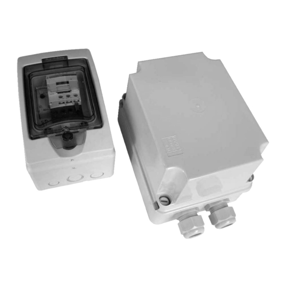
Summary of Contents for Mastervolt MASTERSWITCH 0
- Page 1 INSTALLATION AND USERS MANUAL MASTERSWITCH 0 Automatic AC transfer switch...
-
Page 2: Table Of Contents
CONTENTS CONTENTS: v 4.0. November 2006 GENERAL INFORMATION.............................. 3 Use of this manual.............................. 3 Guarantee Specifications ........................... 3 Quality ................................3 Validity of this manual ............................3 Liability ................................3 Identification label............................... 3 SAFETY GUIDELINES AND MEASURES ........................4 Warnings and symbols ............................4 Use for intended purpose ........................... -
Page 3: General Information
GENERAL INFORMATION 1 GENERAL INFORMATION The MASTERVOLT Masterswitch 0 is the heart of the AC QUALITY installation. The Masterswitch 0 is designed to take over During their production and prior to their delivery, all of our manual switching between two different power sources. -
Page 4: Safety Guidelines And Measures
(carefully) follow • Do not work on the Masterswitch 0 or system if it is still the procedures. connected to a power source. Only allow changes in your electrical system to be carried out by qualified USE FOR INTENDED PURPOSE electricians. -
Page 5: How It Works
INPUT 1 when grid is available on INPUT 1. At the same time, INPUT 2 is In this case, the Masterswitch 0 is in a neutral state and denied. The generator or the shore power should be consumes no energy it self. -
Page 6: Installation
See chapter 5 for recommended torques. After unpacking, check the Masterswitch 0 for possible damage. Do not use the Masterswitch 0 if the cabinet is GROUND CONNECTIONS damaged. For safety reasons it is very important that all ground... - Page 7 INPUT 2 Delay time INPUT1 Delay time INPUT1 OUTPUT OUTPUT Masterswitch 0 – 7kW 117V/60A Masterswitch 0 - 5kW 230V/20A Masterswitch 0–9kW 117V/80A Masterswitch 0 - 10kW 230V/40A Masterswitch 0 – 3.5kW 117V/32A Figure 2: Installation of the Masterswitch 0...
-
Page 8: Inputs
PE (ground) Figure 3: DECOMMISSIONING Connections to the AC sources If it is necessary to put the Masterswitch 0 out of operation, follow the instructions in order of succession as OUTPUTS described below: Connect the load to the terminals as indicated in figure 2 and figure 4. -
Page 9: Specifications
95% max., non-condensing Earth leakage breaker (RCCB): N/A, must be applied externally (installation dependent) Automatic circuit breakers: N/A, must be applied externally (installation dependent) 230V VERSIONS Masterswitch 0 - 5kW 230V/20A Masterswitch 0 - 10kW 230V/40A Part number: 55006010 55006015 Nominal voltage: Single phase 200 –... -
Page 10: Outline Drawings
OUTLINE DRAWINGS 6 OUTLINE DRAWINGS Masterswitch 0 - 5kW 230V/20A Masterswitch 0 - 10kW 230V/40A Masterswitch 0 – 3.5kW 117V/32A Masterswitch 0 – 7kW 117V/60A Masterswitch 0–9kW 117V/80A All dimensions are in millimeters. Figure 5: dimensions of the Masterswitch 0... -
Page 11: Ec Declaration Of Confirmity
EC DECLARATION OF CONFIRMITY 7 EC DECLARATION OF CONFIRMITY Herewith declares that: Product: 55006010 Masterswitch 0 – 5kW 230V/20A 55006015 Masterswitch 0 – 10kW 230V/40A 55106000 Masterswitch 0 – 3.5kW 117V/32A 55106100 Masterswitch 0 – 7kW 117V/60A 55106200 Masterswitch 0 – 9kW 117V/80A...


Need help?
Do you have a question about the MASTERSWITCH 0 and is the answer not in the manual?
Questions and answers