
Related Manuals for Presys PCON-Y18-LP


Summary of Contents for Presys PCON-Y18-LP
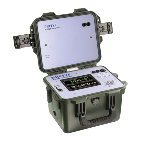
- Page 1 PCON-Y18-LP Automatic Low Pressure Calibrator www.presys.com.br Desktop version Field Service version Rack Mounting version Technical Manual EM0345-02...
- Page 2 ATTENTION! To prevent damage to the connected instrument to be calibrated, do not turn off the PCON-Y18-LP with the CONTROL mode selected. Before turning off, select MEASURE or VENT mode.
- Page 3 It is mandatory to use filters in out port (HI). ATTENTION! Whenever you change the inclination of the PCON-Y18-LP, it is important to perform the RESET operation of the pressure again. CAUTION: Damage caused by failure to observe the above recommendations results in total or partial loss of the equipment warranty.
- Page 4 EC Directives when installed in accordance with the installation instructions contained in the product documentation: Series PCON-Y18-LP Description Automatic Low Pressure Calibrator 2014/35/EC of the European Parliament and of the Council of 12 December 2006 on...
-
Page 5: Table Of Contents
PRESYS Instruments PCON-Y18-LP Table of Contents 1 - Introduction ..........................1 1.1. General Description ......................... 1 1.2. Technical Specifications ......................2 1.3. Special Software Features....................... 4 1.4. Order Code ..........................5 1.5. Parts Identification ........................6 2 - Calibrator Operation ........................8 2.1. -
Page 6: Introduction
This is possible due to an embedded calibrator specific for these types of signal, including current 4-20 mA. Thus, PCON-Y18-LP incorporates the functions of pressure controller, digital pressure standard and calibrator for mA, V, mV, ohms and RTD. -
Page 7: Technical Specifications
PRESYS Instruments PCON-Y18-LP 1.2. Technical Specifications 1.2.1. Pressure Control Module Choose one range for the Pressure Control Module between -100 to 100 Pa (-1 to 1 mbar) and -35000 to 35000 Pa (-350 to 350 mbar). SI-Pascal Resolution Control Stability... - Page 8 PRESYS Instruments PCON-Y18-LP 1.2.3. General Specifications Thirty minutes warm-up time. Transmitter power supply (TPS): 24 Vdc, with protection from short circuit (30 mA). Contact input for calibration of pressure switches. Operating temperature range: 0 to 50 C. Relative Humidity: 0 to 90 % RH.
-
Page 9: Special Software Features
PRESYS Instruments PCON-Y18-LP 1.3. Special Software Features - PRESET POINTS: edit your most frequently used setpoints and access them quickly. - STEP: steps or setpoints with configurable time. - STABILITY/LEAK TEST: measures the variation of the signal (be it Pressure or an Auxiliary Input signal) within a configurable period. -
Page 10: Order Code
PRESYS Instruments PCON-Y18-LP 1.4. Order Code Page 5... -
Page 11: Parts Identification
PRESYS Instruments PCON-Y18-LP 1.5. Parts Identification DT Version - Desktop Fig. 01 – DT Version Page 6... - Page 12 PRESYS Instruments PCON-Y18-LP RM Version – Rack Mounting Fig. 02 – RM Version Fig. 03 – FS Version Notes: On the FS Version, the VENT is an internal port, not accessible to the user. Page 7...
-
Page 13: Calibrator Operation
DATA LOGGER – record measurements, enabling visualization on chart or table, see section 2.4. VIDEOS – features videos made by Presys to assist in the use of the calibrator, and can also store videos made by the user, see section 2.5. -
Page 14: Calibrator Menu
To select the Pressure Control Module and the Auxiliary Input functions press the CALIBRATOR button from the main menu. When first entering the CALIBRATOR menu, the PCON-Y18-LP executes a VENT operation and an AUTO RESET of the pressure read in the Pressure Control Module. -
Page 15: Pressure Control Module - Connections
PCON-Y18-LP 2.1.1. Pressure Control Module – Connections PCON-Y18-LP controls the pressure in the output port with high precision and stability. To control the pressure, an integrated electric pump for positive and negative pressure generation supplies the pressure for the controller. When the calibrator is switched on, the electric pump is turned on and provides the required pressure for the entire range of the calibrator. - Page 16 ATTENTION! To prevent damage to the connected instrument to be calibrated, do not turn off the PCON-Y18-LP with the CONTROL mode selected. Before turning off, select MEASURE or VENT mode. IMPORTANT! All pressure equipment and accessories (such as hoses, connections, adapters, etc.) connected to the calibrator must be clean, free of residues...
-
Page 17: Measure Mode
PRESYS Instruments PCON-Y18-LP 2.1.2. Measure Mode In Measure mode, the calibrator shows the pressure measurement in the Control Module. In this state, the control mode is disabled. Fig. 09 - Measure mode – screen Note: The FS Version (Field Service) has an internal VENT port, not accessible to the user. - Page 18 Fig. 11 - Output Isolation Valve Status To zero the current pressure measurement, press the RESET PRESS button. Whenever this function is used, the PCON-Y18-LP executes a VENT operation and an AUTO RESET of the pressure read in the Pressure Control Module and returns to the control mode.
-
Page 19: Control Mode
PRESYS Instruments PCON-Y18-LP 2.1.3. Control Mode In this mode, the calibrator controls pressure at the output port through the admission and exhaustion control valves. Fig. 13 - Control mode – screen Note: The FS Version (Field Service) has an internal VENT port, not accessible to the user. -
Page 20: A) Range Parameters
PRESYS Instruments PCON-Y18-LP a) Range Parameters WARNING! Before connecting the instrument under test to the output port it is recommended to configure the output range parameters. These parameters limit the controller output range, in order to protect the instrument under test. -
Page 21: B) Changing The Setpoint
PRESYS Instruments PCON-Y18-LP b) Changing the set point Press the SP button or touch the Indicated Value to change the set point to the desired value. When the pressure is stabilized, its reading value turns to green. Fig. 16 - Control Mode – Changing Set point Value The state of the output isolation valve is user configurable. -
Page 22: C) Stabilization Settings
Fig. 18 - Stabilization Settings d) Control Settings The PCON-Y18-LP has a linear controller output behavior when the set point is changed. It means that the output varies linearly according to the parameter SP Slew Rate (Pressure Unit / second). The controlled pressure will be closer to the linear behavior for lower values of pressure rate, protecting the instrument under test from overshoot. - Page 23 PRESYS Instruments PCON-Y18-LP Edit the Control Parameter by pressing the SETTINGS button shown below. Go to the CONTROL tab and edit the SP Slew Rate (in current pressure unit / second). Fig. 20 - Control Parameters Increasing the flow the output tends to be more stable, but it may cause overshoot.
-
Page 24: E) Preset Setpoints
Another fast way to change the set point to the preset values is using a numeric keyboard connected to the PCON-Y18-LP Type A USB (see section 1.5 – Parts Identification). In Control Mode, when pressing from 0 to 7 in the keyboard the corresponding preset set points P1 to P8 will be controlled. -
Page 25: G) Nudge Function
In this case, to move to the next step you must press the next set point value button. By pressing the previous set point button, it returns a step. If the Wait Stabilize box is selected, the PCON-Y18-LP will wait for pressure stabilization before changing to the next set point. -
Page 26: Vent Mode
Instruments PCON-Y18-LP If you are using a numeric keyboard connected to the PCON-Y18-LP Type A USB (see section 1.5 – Parts Identification), you can increment and decrement the set point by pressing the “+” and “-” buttons in the keyboard. - Page 27 PRESYS Instruments PCON-Y18-LP Fig. 26 - Vent mode – screen Note: The FS Version (Field Service) has an internal VENT port, not accessible to the user. Fig. 27 - Vent mode – state of the valves The state of the output isolation valve is user configurable. To change the state of the valve, press the SETTINGS button shown below and change the Output Parameters (OPEN / CLOSED) in the ADVANCED tab.
- Page 28 Fig. 28 - Output Isolation Valve Status To zero the current pressure measurement, press the RESET PRESS button. Whenever this function is used, the PCON-Y18-LP performs a VENT operation and an AUTO RESET of the pressure read in the Pressure Control module and returns to the CONTROL mode.
-
Page 29: Changing The Engineering Unit
PRESYS Instruments PCON-Y18-LP When the VENT mode is started, first the calibrator reads the pressure in the control module. If the pressure measurement is below the Vent Opening Limit value, the control is shut off and the VENT valve opens. Otherwise, if the pressure is above this limit, the controller reduces the pressure down to the Vent Opening Limit value by varying it according to the Vent Rate parameter. -
Page 30: Auxiliar Input
PRESYS Instruments PCON-Y18-LP Fig. 32 - Filter Intensity Fig. 33 - Filter Indication 2.1.7. Auxiliary Input At the bottom of the screen, an input can be configured. When an input is selected, the screen will split automatically, showing two simultaneous variables. To select an input, just touch the INPUT bar. - Page 31 For OHM and RTD measurement, you should also select between 2, 3 or 4 wires options. The SWITCH input is a measurement of continuity of an external contact connected to the input (between RTD1 and RTD4) of PCON-Y18-LP. When there is continuity, the entry shows CLOSED, otherwise it shows OPEN.
- Page 32 PRESYS Instruments PCON-Y18-LP Fig. 37 - Auxiliary Input Connections Page 27...
-
Page 33: Transmitter Power Supply (Tps)
Instruments PCON-Y18-LP 2.1.8. Transmitter Power Supply (TPS) The PCON-Y18-LP has the TPS (transmitter power supply), 24 Vdc, galvanically isolated and provided with short-circuit protection (current limited to 30 mA). Fig. 38 - TPS Power Supply 2.1.9. Auxiliary Input Scale Function... - Page 34 PCON-Y18-LP SCALE Function Fig. 40 - SCALE Function (LINEAR) It establishes a linear relationship between the PCON-Y18-LP input signal and what is shown on the display, according to the graphic below: Fig. 41 - SCALE Function (LINEAR) The scaled indication on the display (#) may represent any engineering unit, such as: m/s, m ³...
-
Page 35: Calibration Examples
PCON-Y18-LP 2.1.10. Calibration Examples a) Pressure Transmitter Calibration Use the PCON-Y18-LP TPS source (24 Vdc) to power up a two-wire transmitter Select mA (current) in the Input and connect the current as illustrated below. (Auxiliary) menu and configure the Pressure Control parameters. -
Page 36: B) Pressure Switch Verification
The relay is activated whenever the pressure passes above or below a certain setpoint alarm. Connect the pressure switch relay output to the switch input of PCON-Y18-LP, RTD1 and RTD4 terminals, and make the pneumatic connections as illustrated in the figure below. - Page 37 Then PCON-Y18-LP starts to decrease the output pressure to find a transition switch from opened to closed, in order to calculate the hysteresis.
-
Page 38: Leakage / Stability Test
To do the test, put the PCON-Y18-LP in Measure mode (the pressure control valves are off) and select the Input desired (the leakage / stability test may be done with any of the Auxiliary Input signals, for testing the pressure in the control module select PRESSURE →... - Page 39 PRESYS Instruments PCON-Y18-LP Press the icon to go to the Leak/Stability Test. Fig. 49 - Leak/Stability Test - screen Define the test duration (in seconds) and press the START button. Fig. 50 - Leak/Stability Test - results During the test, you can increase the test time by pressing the +20s button. The S, M and H buttons change the time unit to second, minute and hour, respectively.
-
Page 40: Hart
PRESYS Instruments PCON-Y18-LP 2.2. HART ® PCON-Y18-LP can be used to read and set parameters in devices that have ® ® HART Communication Protocol. The HART Protocol allows digital communication between master (in this case, PCON-Y18-LP) and the slave (field instrument) superimposed on the 4-20 mA analog signal. - Page 41 IMPORTANT: Before connecting the calibrator to the transmitter(s) as shown above, make sure that the mA input is not selected in the PCON-Y18-LP (Enter the Calibrator menu and select any other auxiliary input than mA or select the option NONE)
-
Page 42: Starting Communication
PRESYS Instruments PCON-Y18-LP For the connection shown in Figure 53, use the option ONLY HART ® . In this ® mode, the internal resistor and the mA input are disabled. The HART resistor (at least 250 ) must be externally inserted in series with the power source and the transmitter. In this case, the calibrator does not perform the measurement of the transmitter current, but ®... -
Page 43: Adjusting The Measurement Range Of A Hart ® Transmitter (Ch Option)
PRESYS Instruments PCON-Y18-LP 2.2.3. Adjusting the Measurement Range of a HART Transmitter ® (CH Option) While the instrument is being connected, in the DEVICE INFO tab are shown information about instrument identification, such as TAG, manufacturer, description, message, date, measuring range and damping filter. Some of these parameters can be changed in DEFAULT SETTINGS. -
Page 44: Adjusting The Measurement Range Of A Hart ® Transmitter With Reference (Ch Option)
HART (digital), the current that the transmitter wants to generate (AO - DIGITAL OUTPUT), and the current measured by PCON-Y18-LP (ANALOGIC READ). Set the pressure controlled pressing OUTPUT and adjust the transmitter range by pressing the ↓ Inf Range and ↑ Sup. Range buttons. - Page 45 In DEFAULT SETTINGS tab the output current of the HART transmitter (output trim) can be adjusted according to current measured by the calibrator. You can make this adjustment only when the PCON-Y18-LP is connected to a single transmitter with ® address 0, in the mA INPUT + HART option of connection, since the calibrator needs to measure the current to make the adjustment.
-
Page 46: Full-Hart Configurator (Fh Option)
(DD library). To start the HART configurator you must wait for the PCON-Y18-LP read all the instrument parameters. The PCON-Y18-LP will display the message: Reading device information. - Page 47 PRESYS Instruments PCON-Y18-LP To view the value of mA input or change the output set point, press the button Fig. 60 - Calibrator / Controller Input and Output Values To view the status of the device, enter the VIEW menu and then DEVICE CONDITION: Fig.
-
Page 48: Automatic Tasks
PCON-Y18-LP also creates and performs tasks for calibration of analog gauges, using the inverted calibration method, so the user can change the control set points in small steps until the expected value is being indicated on the gauge. - Page 49 Go to the As Found/ As Left tab. Add each point to be generated by the PCON-Y18-LP and the expected value for the instrument under calibration, for both As found (calibration done before adjustment) and As left (calibration done after adjustment).
-
Page 50: Performing Tasks
START. Fig. 66 - Exploring tasks PCON-Y18-LP automatically starts the calibration by generating the set points registered in the task and doing the reading of the instrument to be calibrated. If you select the NONE option for the input, for each generated point the calibrator requires the value read by the instrument. -
Page 51: Viewing Results
2.3.3. Viewing Results Once a task has been performed, it remains saved in the calibrator. To view the results of a calibration by the PCON-Y18-LP, select TASKS in the main menu. Enable the ● PERFORMED option. The list will show only the tasks that have been performed. - Page 52 USB cable to the USB Type A port of the computer (USB type A) and the USB Device port of the PCON-Y18-LP (USB type B for version RM, and USB micro type for the DT version, see section 1.5 – Parts Identification).
-
Page 53: Data Logger
The logo can be changed to one of your own company. To do this, connect a USB cable between the USB Device port of the PCON-Y18-LP and the USB Type A port on the computer. Change the LOGO.bmp file to your logo file (it should have a .bmp extension). -
Page 54: Videos
If a Pen Drive is not connected, these files are saved in the internal SD card of the calibrator. To access the files saved on the PCON-Y18-LP internal memory, connect the USB cable to the computer (type A USB) and to the PCON-Y18-LP (Micro-B USB, see section 1.5 –... -
Page 55: Settings
PRESYS Instruments PCON-Y18-LP 2.6. Settings 2.6.1. System In the SYSTEM tab you can set the volume of the calibrator, the touch screen calibration, identification of the calibrator, language, printer and security options. Touch screen Options • To adjust the touch screen, press the TOUCHSCREEN OPTIONS button. -
Page 56: Built-In Web Server
To lock the system, press the padlock icon in the system menu. The next time PCON-Y18-LP is turned on, it will request login and password. To unlock the system, login as an Admin Level user and press the padlock icon in the system menu again. -
Page 57: Scpi Commands Set
To control the calibrator using the SCPI commands connect a serial cable to the PCON-Y18-LP USB Type A port (see section 1.5 – Parts Identification). Connect the cable to the serial port of the computer. At the menu Settings → Network → Serial... - Page 58 PRESYS Instruments PCON-Y18-LP MEASure:PRESsure? Description: Pressure Reading. Parameters: --- Response: Pressure Reading|Unit|Stability UNIT[:PRESsure]? Description: Current Pressure Unit. Parameters: --- Response: Current Pressure Unit UNIT[:PRESsure] <unit> Description: Sets the Pressure Unit. Parameters: New Pressure Unit Response: --- SYSTem:ERRor[:NEXT]? Description: Checks the Errors List.
-
Page 59: Maintenance
Replace the fuse once. If a second fuse blows again, it is because the fault is not that simple. In this case, contact the Presys technical support (see section 1.5 – Parts Identification – Power Supply Fuse) Fuse specification:... -
Page 60: Pressure Units Conversion
PRESYS Instruments PCON-Y18-LP 4 - Pressure Units Conversion mbar 0.06894757 68.94757 0.006894757 6.894757 6894.757 0.06804596 0.07030695 703.0890 O@4°C O@60°F 70.30889 2.306726 27.68067 27.70759 torr mmHg cmHg inHg 51.71507 51.71507 5.171507 2.036026 inHg@60°F gf/cm kgf/cm kgf/m 2.041772 70.30695 0.07030695 703.0695... - Page 61 www.presys.com.br...
Need help?
Do you have a question about the PCON-Y18-LP and is the answer not in the manual?
Questions and answers