
Related Manuals for Pelton & Crane Caseworx SIDE CABINET


Summary of Contents for Pelton & Crane Caseworx SIDE CABINET
- Page 1 Caseworx SIDE CABINET AND MILLENIUM CABINET Use & Care -AND- Installation Instructions...
-
Page 2: Table Of Contents
TablE oF ConTEnTS OVERVIEW ..........................................3-4 SS OVERVIEW ........................................5 SD OVERVIEW ......................................... 6 PREPaRIng thE SItE......................................7-8 UPPER MODULE InStaLLatIOn ..................................9-11 CaBInEt InStaLLatIOn ......................................12-15 MILLEnnIUM REaR COLUMn InStaLLatIOn ..............................15 DOOR & DRaWER aDjUStMEnt ..................................16 taPMaStER FaUCEt SERVICE InFORMatIOn ..............................17 CLEanIng, DISInFECtIng &... -
Page 3: Overview
Ambient Temperature: 68°F to 76°F (20°C to 25°C) Relative Humidity: 20% to 60% non-condensing Atmospheric Pressure: 13.1 to 15.3 PSI (900 to 1050hPa) Technical Description Model Designation: Caseworx Side Cabinet SToRaGE anD TRanSPoRTaTIon Temperature : -68°F to 122°F (-55°C to 50°C) - Page 4 oVERVIEW Review the safety warnings and instructions before using the device to avoid injury and to prevent damage to this equipment. The manufacturer’s liability is applicable only if the device is used in compliance with the directions and safety warnings provided in this manual. Use only Pelton and Crane replacement parts.
-
Page 5: Ss Overview
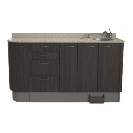
SS oVERVIEW A, sink and waste module B-C, storage module D, sink E, counter top F, waste container G, faucet H, soap dispenser I, contour module The SS cabinet provides a work surface and storage. It is designed with the Dentist and staff in mind to provide a robust working environment for the daily activities of performing dentistry. -
Page 6: Sd Overview
SD oVERVIEW A, sink and waste module B-C, unit mount area D, sink E, counter top F, waste container G, faucet H, soap dispenser I, contour module The SD cabinet provides a work surface, storage, and can be installed with or without a Pelton & Crane delivery system. -
Page 7: Preparing The Site
PREPaRInG THE SITE WaRnInG: Always lift cabinets by bottom edge, being careful to lift with your legs and not your back. WaRnInG: Make all required, air water and drain attachments from the utilities to the incoming stub-up connections before the delivery system installation occurs. Doing so prevents damage to the utility lines from heat associated with some plumbing connection methods. - Page 8 PREPaRInG THE SITE Wall Template 9 o’clock 3 o’ clock noTE: The template illustration depicts the mounting points. 1. Lay installation template over plumbing stub-ups and check the distance from the cabinet to the walls according to operatory layout. (Generic floor template and wall template are depicted in illustration. Electrical and plumbing templates for standard cabinets may be furnished on request.) 2.
-
Page 9: Upper Module Installation
UPPER MoDUlE InSTallaTIon WaRnInG: Upper cabinets should only be mounted by following the instructions in this manual and using the hanging rail system provided with your cabinet. Do not attempt to hang cabinets via screws through the back panel. 1. Determine the height to the top of the upper cabinet and mark location on the wall. (Figure 1) •72”... - Page 10 One piece wing plate UPPER MoDUlE InSTallaTIon 5. Install 3” pan head screw with washer into each stud behind the hanging rail. 6. Prepare the cabinets for hanging. We suggest removing the cabinet doors and shelves before hanging. The hinges are ‘snap-on/off’ and can easily be removed by pulling the WARNING: tab marked “pull”...
- Page 11 UPPER MoDUlE InSTallaTIon 9. The cabinets can now be adjusted using the adjusting screws on the hanger hardware, and up or down until level and plumb. Start by adjusting bottom screw A clockwise untilcabinets are pulled firm against wall. After all cabinets are firm against wall, adjust cabinets until level using top screw B.
-
Page 12: Cabinet Installation
CabInET InSTallaTIon 1. Remove packaging from side cabinet. Before installing the side cabinet inspect the cabinet for damage and verify that all items on the quick install package checklist are in the packaging. Remove drawers and unclip doors. Set aside in a safe area until they are to be reinstalled. - Page 13 CabInET InSTallaTIon 3. Using a level on the counter top, level the side cabinet using the leveling feet as shown. Re-install false bot- toms after leveling feet. For Millennium Rear Cabinets only: Secure the cabinet to the floor using the appropriate fastener. Concrete Floor: Four 1/2”...
- Page 14 CabInET InSTallaTIon 5. If backsplash is seperate from the cabinet, install the back splash against the wall and top of the countertop using the clear silicone provided. 6. Install the water faucet and soap dispenser into the module top according to the manufacturer’s installation instructions 7.
-
Page 15: Millennium Rear Column Installation
CabInET InSTallaTIon 8. Re-install doors removed previously, taking care to place them in their original positions. Adjust hinges as needed. MIllEnnIUM REaR ColUMn InSTallaTIon 1.Remove the front panel from the wire chase column. Set aside in a safe area until it is to be reinstalled. 2.Align the column so that it is centered on the base mod- ule. -
Page 16: Door & Drawer Adjustment
DooR & DRaWER aDjUSTMEnT Note : Upper & lower plates Cam w ing mounting plate must be moved together for each door Range (5/32") Cam Screw One piece wing plate Note : Upper & lower plates must be moved together for each door Range (5/32") over-adjusting hinges can cause damage WARNING:... -
Page 17: Tapmaster Faucet Service Information
TaPMaSTER FaUCET SERVICE InFoRMaTIon REMEDY SYMPToMS CaUSE In most situations, depending Tapmaster leaking and/or These symptoms are generally upon accessibility, debris may noise problems in valve blocks. caused by water-borne debris lodged be removed from the valve in the valve block porting and/or (Note: Tapmaster uses a dif- blocks without removing them ferential pressure principle to... -
Page 18: Cleaning, Disinfecting & Sterilization
ClEanInG, DISInFECTInG & STERIlIZaTIon Equipment can be cleaned with a solution of mild detergent IMPoRTanT: Do not use powdered cleansers, scouring and warm water. A variety of surface disinfectants are pads or abrasive scrubbers on any of the painted, plastic available for use in dental treatment rooms. -
Page 19: Cleaning Cabinetry Surfaces
ClEanInG CabInETRY SURFaCES IMPORTANT: When buffing, sanding or applying abrasive Disinfecting the Surfaces cleansers, always use a circular motion to preserve the Disinfect cabinet surfaces by spraying or wiping with original countertop finish. surface disinfectant using the spray-wipe-spray tech- nique as endorsed by OSAP (Office Sterilization and Cuts and Scratches- STAINLESS STEEL SINK ONLY Asepsis Procedures). -
Page 20: Dimensional Data Drawings
DIMEnSIonal DaTa DRaWInGS note: Back splash is 2 ” for solid surface, 4” for stone or HPL surfaces. M-SS211/ M-SS201/ M-SS221 M-SS231 M-SD210/ M-SD200/ M-SD220 M-SD230 M-SS511/ M-SS501/ M-SS521 M-SS531 M-SS151-9 M-SS150-3 M-SS131-9 M-SS130-3 049336 R02... - Page 21 DIMEnSIonal DaTa DRaWInGS note: Back splash is 2 ” for solid surface, 4” for stone or HPL surfaces. M-SSR146 Std Column Std Upper M-SSR146 Std Column CPU Upper 45.9 45.9 12.0 12.0 12.0 24.0 14.0 14.0 12.0 12.0 M-SSR146 Tall Column Std Upper M-SSR146 Tall Column CPU Upper 45.9 45.9...
-
Page 22: Installation And Servicing Checklist
InSTallaTIon anD SERVICInG CHECKlIST Verify the following after installation or servicing of the cabinet: All manuals are present. All labels are present and legible. No mechanical damage on new installations. The cabinet is connected to the correct power source. There are no water or air leaks. All the cabinet adjustments have been made according to the users manual. -
Page 23: Notes
noTES 049336 R02... - Page 24 ©2015, Pelton & Crane 11727 Fruehauf Drive P/n 049336 Rev 02 Charlotte, NC, 28273 - USA 11/17/15 www.pelton.net Printed in USA We reserve the right to make any alterations which may be due to any technical improvements 049336 R02...
Need help?
Do you have a question about the Caseworx SIDE CABINET and is the answer not in the manual?
Questions and answers