Table of Contents
Advertisement
Quick Links
Advertisement
Table of Contents

Related Manuals for Pelton & Crane Centennial 2 FS Series


Summary of Contents for Pelton & Crane Centennial 2 FS Series
- Page 1 FS Series Centennial 2 Installation Instructions RD Series OS Series...
-
Page 2: Table Of Contents
TABLE OF CONTENTS DEFINITION OF SYMBOLS ......................................3 SAFETY ............................................3 OVERVIEW OF CONFIGURATIONS ....................................4 FLEXIBLE SUPPORT CENTER DIMENSIONS ................................5 REAR DELIVERY CENTER DIMENSIONS ..................................8 OPERATORY SUPPORT CENTER DIMENSIONS ................................10 TEMPLATES ..........................................12 PREPARING THE SITE........................................18 SPECIFICATIONS ......................................... -
Page 3: Definition Of Symbols
DEFINITION OF SYMBOLS The following symbols and terms may be used throughout this manual and your equipment: Indicates conformity to General Requirements for Safety is certified by Intertek Testing Services. WARNING: Failure to carefully follow the described procedure may result in damage General mandatory action required, important to to the equipment and/or injury to the patient/ operator. -
Page 4: Overview Of Configurations
OVERVIEW OF CONFIGURATION (SHOWN WITHOUT OPTIONAL DELIVERY UNIT ATTACHMENTS) OS42-2 064380 R00... -
Page 5: Flexible Support Center Dimensions
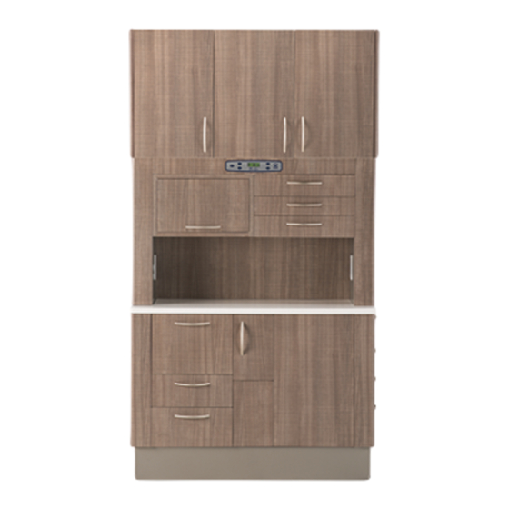
FLEXIBLE SUPPORT CENTER DIMENSIONS FS36-2 (Shown with Standard Upper Cabinet) FS36B-2 (Shown without Upper Cabinet) 064380 R00... - Page 6 FLEXIBLE SUPPORT CENTER DIMENSIONS FS36M-2 13 1/2 FS42-2 (Shown with Standard Upper Cabinet) 064380 R00...
- Page 7 FLEXIBLE SUPPORT CENTER DIMENSIONS FS42B-2 (Shown without Upper Cabinet) FS42M-2 064380 R00...
-
Page 8: Rear Delivery Center Dimensions
REAR DELIVERY CENTER DIMENSIONS RD36-2 (Shown with Standard Upper Cabinet) RD36B-2 (Shown without Upper Cabinet) 064380 R00... - Page 9 REAR DELIVERY CENTER DIMENSIONS RD42-2 (Shown with Standard Upper Cabinet) RD42B-2 (Shown without Upper Cabinet) 064380 R00...
-
Page 10: Operatory Support Center Dimensions
OPERATORY SUPPORT CENTER DIMENSIONS OS42-2 (Shown with Standard Upper Cabinet) OS42B-2 (Shown without Upper Cabinet) 064380 R00... - Page 11 OPERATORY SUPPORT CENTER DIMENSIONS OS42-L-2 (Shown with Standard Upper Cabinet) OS42B-L-2 (Shown without Upper Cabinet) 064380 R00...
-
Page 12: Templates
TEMPLATES FS42-2 FLOOR TEMPLATE 064380 R00... - Page 13 TEMPLATES FS36-2 FLOOR TEMPLATE 064380 R00...
- Page 14 TEMPLATES RD42-2 FLOOR TEMPLATE 064380 R00...
- Page 15 TEMPLATES RD36-2 FLOOR TEMPLATE 064380 R00...
- Page 16 TEMPLATES OS42-2 FLOOR TEMPLATE 064380 R00...
- Page 17 TEMPLATES WALL UTILITY TEMPLATE (ALL MODELS) 064380 R00...
-
Page 18: Preparing The Site
PREPARING THE SITE SPECIFICATIONS WARNING: Always lift cabinets by bottom edge Electrical: Connect to a 120 VAC, 15 AMP circuit. 1/2” (not by the doors or drawers), being careful to lift conduit and quad box needed to connect conduit from with your legs and not your back. -
Page 19: Cabinet Installation
CABINET INSTALLATION SECURING THE CABINET TO THE FLOOR These installation instructions describe the NOTE: procedures with the technician facing the front of the unit. WARNING: Be sure the main power is turned off at the installation site. WARNING: The cabinet should be appropriately secured to floor before any unit or anything else is installed. - Page 20 LEVELING THE CABINET 6. Side to 5. Front to Back: Place level vertically on outside Side Level front of cabinet. Using the shims located in hardware packaging, place shims (as required) on the inside of cabinet underneath the side frame of cabinet base (where shims won’t be seen).
-
Page 21: Installation Assistant's Countertop
INSTALLING ASSISTANT’S COUNTERTOP (OS CABINET ONLY) 1. Locate the stop bracket underneath countertop and remove screws and bracket (to avoid interference when installing the countertop). 2. Remove top side drawer for access to underside of countertop. Place countertop (with slides attached) on cabinet as shown. -
Page 22: Electrical Checklist
ELECTRICAL CHECKLIST ELECTRICAL SUPPLY WARNING: The total electrical capacity for the cabinet is listed at 12 amps., with a 15 amps. circuit breaker service. Ensure optional equipment plugged into the outlets do not exceed over 12 amps.. Before beginning the following steps, have a licensed electrician properly wire cabinet to meet all local codes and provide cabinet with power. - Page 23 INSTALL TRIM PLATES After cabinet and all delivery units are installed and fully functional, install trim plates. Using a 1/8” Allen wrench and four screws (A) (two on each side of cabinet), secure the kick plates (B) to the bottom of the side frames. SET CLOCK TIME Set proper clock time.
-
Page 24: Installation And Servicing Checklist
INSTALLATION AND SERVICING CHECKLIST VERIFY THE FOLLOWING AFTER INSTALLATION OR SERVICING OF THE UNIT: All manuals are present. All labels are present and legible. No mechanical damage on cabinet. The cabinet is connected to the correct power source. The cabinet is properly and securely bolted to the floor and is level and stable Their are no water or air leaks. - Page 25 NOTES 064380 R00...
- Page 26 We reserve the right to make any alterations which may be due to any technical improvements. ©2015, Pelton & Crane P/N 064380 Rev. 00, 02/18/2015 11727 Fruehauf Drive Printed in USA Charlotte, NC 28273 USA www.pelton.net...
Need help?
Do you have a question about the Centennial 2 FS Series and is the answer not in the manual?
Questions and answers