Table of Contents
Advertisement
Advertisement
Table of Contents

Related Manuals for Pelton & Crane Executive EX50


Summary of Contents for Pelton & Crane Executive EX50
- Page 1 Model: EX50 Use & Care...
-
Page 2: Table Of Contents
O OUR USTOMER Thank you for purchasing your new Executive Cabinetry. It is engineered to provide many years of reliable performance. However, a certain amount of care is required. Conscientious adherence to the Maintenance Instructions will ensure that your unit will function to your satisfaction for many years to come. Therefore, we have provided you with a set of technical literature, which should be kept for quick and easy refer- ence. -
Page 3: Familiarization
EGULATORY NFORMATION Safety Notes This unit is not used in rooms where an explosion hazard exists. The pre-installation of the facility must be performed in accordance with the requirements outlined in our "Pre-installa- tion" Instructions. As the manufacturer of dental equipment, we can only assume responsibility from the safety related performance of the unit, if maintenance and repair are carried out by the manufacturer, or by agencies authorized by Pelton &... -
Page 4: Cabinetry Identification
AMILIARIZATION Cabinetry Identification 1.b. 1.a. 1.a. 1. Upper Storage 2. Midsection 2.a. 2.a. 2.b. 3.a. 3.a. 3. Countertop 4. Base Section 4.a. 4.a. 4.b. 1. UPPER CABINET 3. SOLID SURFACE COUNTERTOPS a.Left / Right Storage- Pull down module provides a. Two pullout countertops that brings the work open storage for auxiliary equipment. -
Page 5: Upper Storage
AMILIARIZATION Upper Storage 1. The left and right center pull down modules (A) provide storage for most optional dental equipment. An elec- trical cutout (B) is located inside of each of module. These cutouts provide access to the electrical supply when storing optional equipment inside of modules. -
Page 6: Midsection
AMILIARIZATION Midsection 4. The left and right center flip up modules (E) provide two dedicated electrical outlets and can accommo- date frequently used dental equipment such as amal- gamator and x-ray view box. Once procedure is com- pleted the equipment can be stored inside the mod- Zone A ules. - Page 7 AMILIARIZATION Executive doctor’s delivery (K) is equipped with one quick clean syringe and three handpiece holders that swivels for custom positioning. Also standard is a stainless steel tray positioned on the delivery control. Assistant’s instrumentation (L) is equipped with one quick clean syringe, an autoclavable HVE and saliva ejector.
-
Page 8: Operation
PERATION Cabinetry Function Electrical Supply Electrical power for the cabinet is supplied by the 115V main power source for the operatory. The Executive is equipped with a constant power switch (A) located on the wall of the center base cabinet. Flip switch up to have constant power to the cabinetry and Aux. - Page 9 PERATION Cabinetry Function Control Panel Function The control panel is located in the upper center sec- tion below the drawer modules. This panel controls power to the auxiliary equipment and the year, month, date, and time can be set. Also a timer is available when monitoring the time for a dental procedure.
-
Page 10: Foot Control
PERATION Cabinetry Function Florescent Light (A) Two 12”-10 watt fluorescent task lights located in the midsections, are automatically activated when the control panel’s power switch is ON. The lights will remain on until the control panel power is deacti- vated. Foot Control Function The foot control controls drive air and coolant wa- ter for the treatment instruments. - Page 11 PERATION Doctor’s Delivery System Function Master On/Off Toggle (A) Flip switch to “ON” to activate air and water to the doctor’s delivery. When unit is not in use, switch unit to the “OFF” position. AIR COO LANT WA TER CO OL ON/OFF AN T CAUTION: To prevent accidental flooding, it...
- Page 12 PERATION Doctor’s Delivery System Function CAUTION: Never operate any handpiece with- out a bur in the chuck. When there is no bur in place, parts of the chuck are loose, caus- ing the turbine to be out of balance, poten- tially damaging the handpiece.
-
Page 13: Assistant's Instrumentation Function
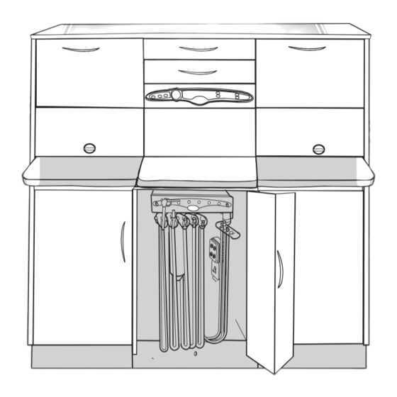
PERATION Assistant’s Instrumentation Function Unit Quick Connect The assistant’s instrumentation can be utilized in four different locations. Two connectors are located on each front bottom corner of the doctor’s delivery (A). The other two are located underneath the front corner of the pull out countertops (B) therefore pro- viding left or right assistant’s delivery. -
Page 14: Integrated Water System
PERATION Integrated Water System CAUTION: Disinfect new water bottle prior to use. Self Contained Water Supply (A) This unit is equipped with a self-contained water system that allows the user to isolate their practice from the municipal water supply. The AIR COO LANT WA TER CO OL ON/OFF... -
Page 15: Maintenance
AINTENANCE DISINFECTING AND STERILIZATION Infection control in the dental office continues to Barrier Technique be a high priority for our customers and end users. The Manufacturer strongly advocates the barrier OSHA, the ADA and the CDC are also involved in this technique be used whenever possible to preserve the finish complex issue. -
Page 16: Cleaning Cabinet Surface
AINTENANCE Cleaning Cabinetry Surfaces Disinfecting the Surfaces Disinfect cabinet surfaces by spraying or wiping with surface disinfectant using the spray-wipe-spray technique as endorsed by OSAP (Office Sterilization and Asepsis Procedures). CAUTION: Follow the manufacturer’s directions for use of disinfectants! Use only the disinfectants that have been tested and approved! For additional infection control as well as to reassure your patients that you are following strong protective prac- tices, we strongly recommend the use of coverings such as plastic, foil or treated paper or autoclavable compo-... -
Page 17: Cleaning Solid Surface Countertop
AINTENANCE Cleaning Solid Surface Countertop General Care Wipe the surface with a damp cloth. If stain develops, clean with soap and water. Or if preferred, Windex ® can be used. Always towel dry to prevent spotting. ® ® CAUTION: Do not use Formula 409 or Fantastik to clean the solid surfacing. -
Page 18: Cleaning Stainless Steel
AINTENANCE Cleaning Stainless Steel Fixtures General Care Clean surface using warm water with a mild non-scratching abrasive powders such as typical household cleaner. Wipe with a sponge or a clean cloth. Do not use steel brushes or steel wool as they may cause scratches and will leave particles embedded on the surface which can lead to RUSTING. -
Page 19: Cleaning System Waterlines
AINTENANCE Cleaning System’s Waterline CAUTION: Wear gloves and eyewear during dental procedures or before performing maintenance on the unit. aily Maintenance Purging with air: At the end of every day, the lines should be purged with air to reduce the growth of biofilm. -
Page 20: Cleaning Assistant's Instrumentation
AINTENANCE Cleaning Assistant’s Instrumentation After Each Patient Draw clean water through each valve, while opening and closing it several times. Leave the valve open for several seconds to allow all of the water to clear the hoses. The HVE and Saliva Ejector tips should always be replaced with sterile ones before each patient. -
Page 21: Sterilization
AINTENANCE Sterilization The procedures given here apply to the vacuum instruments and the autoclavable syringe. Additional information on sterilization and disinfection may be obtained from the American Dental Association and the Centers for Disease Control. NOTE The use of chemical disinfecting agents is not necessary if the instrument is going to be sterilized. Sterilization Dry heat sterilization is not recommended because of There are several methods of sterilization that may be... -
Page 22: Doctor's Delivery
AINTENANCE Doctor’s Delivery Handpiece Oil Collector (A) AIR COO LANT WA TER CO OL ON/OFF AN T The oil collector is located underneath the doctor’s FLU SH delivery. Replace gauzes every 90 days or more often if handpieces are frequently oiled. To replace gauzes, remove the oil collector container and place three 2 x 2 gauzes inside. -
Page 23: Clean Water System
AINTENANCE Clean Water System AIR COO LANT WA TER CO OL ON/OFF AN T FLU SH The water bottle system (D) is designed to optimize the Left Bot tle Rig ht Bot tle quality of water being delivered to the handpieces and syringe. -
Page 24: Adjustment
DJUSTMENTS Testing and Adjusting AIR COOL ANT WAT ER COO ON/OFF LAN T Delivery System FLUSH Leakage Check Ensure that the Master On/Off toggle (A) is in the “OFF” position. Turn on the manual air and water valves located at the utilities inside the sink base. Make a visual and audible inspection for leaks. -
Page 25: Drive Air Adjustment
DJUSTMENTS Assistant’s Tension Adjustment: This adjustment allows the assistant arm assembly to rotate more freely. Extend upper and rear arms straight out. 1) Loosen the 1/16” set screw located in the collar of 1/16” rear arm. Set Screw 2) Using a 7/32” hex drive, turn the adjusting screw located in the collar clockwise to increase tension and counterclockwise to decrease tension. -
Page 26: Doctor's And Assistant's Syringe Adjustment
DJUSTMENTS Doctor’s and Assistant’s Syringe Flow Doctor’s Syringe Flow Adjustment The syringe air and water functions are manually con- trolled by air and water buttons on the syringe head. Adjusting screws allows the control of air and water flow from the syringe to prevent splashing and to achieve a desirable mist. -
Page 27: Check Points Before Operating
HECK OINTS EFORE PERATING Switch power off (A) at the control panel. Turn the manual air (B) and water (C) regulator knobs on. Make a visual and audible inspection for leaks. Switch power on (A) and flip the master on/off toggle AIR COOLA NT WATE R COO ON/OFF... - Page 28 HECK OINTS EFORE PERATING 8. Locate the auto block (J) inside the delivery sys- tem. Locate drive air adjustment stems (K) to ad- just handpiece air. Install handpiece onto connec- tor and activate foot control while observing reading on drive air pressure gauge (L). Adjust handpiece pressure to manufacturer’s require- ments using drive air adjustment stems.
-
Page 29: Product Information
RODUCT NFORMATION Write in the model and serial numbers below for all applicable equipment MODEL: _______________________________ DATE PURCHASED: _____________________ SERIAL NUMBER: ______________________ DATE INSTALLED: _______________________ DEALER NAME AND ADDRESS: MODEL: _______________________________ _______________________________ SERIAL NUMBER: ______________________ _______________________________ _______________________________ _______________________________ MODEL: _______________________________ _______________________________ SERIAL NUMBER: ______________________ Notes / Service History... - Page 30 Pelton & Crane PO Box 7800 Charlotte, NC 28241-7800 ©2006, Pelton & Crane 051740 Order No. Rev. 2, 01/09 We reserve the right to make any alterations which may be due to any technical improvements. Printed in USA...
Need help?
Do you have a question about the Executive EX50 and is the answer not in the manual?
Questions and answers