
Related Manuals for SOLZAIMA FIRE 9KW


Summary of Contents for SOLZAIMA FIRE 9KW
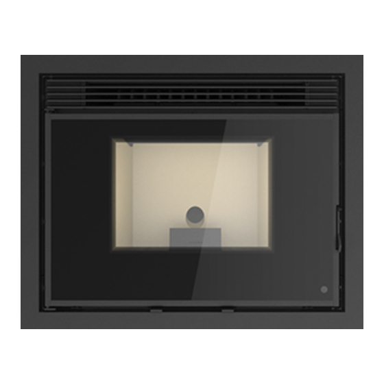
- Page 1 Pellet Insert Instruction Manual Models FIRE 9KW | EARTH 9KW | WIND 9KW Read these instructions carefully before installing, using and servicing the unit. The instruction manual is an integral part of the product. Mod.814-D...
- Page 2 * SOLZAIMA disclaims any responsibility for damages to the unit if installed by non- qualified personnel; * SOLZAIMA is not responsible for any damage to units not installed and used in compliance to the instructions included in this manual; * All local regulations, including but not limited to national and European standards, must be observed when installing, operating and servicing the unit;...
-
Page 3: Table Of Contents
Table of Contents Package Content ....................... 4 1.1. Unpacking the insert .................... 4 1.2..........................4 Safety Precautions ....................6 Advice on action in the event of a fire in a chimney (including equipment)....... 7 Technical Specifications ..................... 8 Installing the Free Standing Pellet Fire ............... - Page 4 15.2.2. General Menu - Service Menu ................ 71 15.2.3. General Menu - Thermostats Menu ..............76 15.2.4. General Menu - Chrono Menu ................ 77 List Alarms / malfunctions / recommendations............83 Instruction for installing the frame ................85 17.1. Choice of frame ................... 85 17.2.
-
Page 5: Package Content
1. Package Content The packaging of the equipment has the following contents: - Pellet Insert models: Fire 9kW, Earth 9kW or Wind 9kW; - Handle for opening the door and extracting the equipment; - Power cable; - Infrared remote control;... - Page 6 • With the two latches open, use them as pullers to separate the movable part from the fixed part attached to the pallet. • Notice. When you open the runner system to the limit, you notice a ledge that locks the moving part, as the ledge passes, the slides are released and the equipment may fall.
-
Page 7: Safety Precautions
Do not touch the pellet insert when barefoot or if any part of your body are wet or humid; • Do not tamper with the safety devices or adjustment features without the SOLZAIMA SA manufacturer's authorization; • It is prohibited to cover or reduce the size of the ventilation openings of the installation;... -
Page 8: Advice On Action In The Event Of A Fire In A Chimney (Including Equipment)
• The unit must be disconnected from the mains power before any maintenance procedures can be performed. Please allow the unit to cool down completely before any maintenance operation (if operating before); • Never touch the interior of the unit without disconnecting it from the power mains. 3. -
Page 9: Technical Specifications
4. Technical Specifications Features Units Fire 9kW Earth 9kW Wind 9kW Weight Height Width Depth Diameter of the fume discharge pipe Reservoir capacity Maximum heating capacity m³ Maximum overall thermal power Minimum thermal power Minimum fuel consumption kg/h Maximum fuel consumption... - Page 10 General Measures Front Back Side Fire 9kW Earth 9kW Wind 9kW Figure 4 – Insertable dimensions to pellets...
-
Page 11: Installing The Free Standing Pellet Fire
The recommended measures for installing the pellet insert are as follows: Model Width (mm) Height (mm) Depth (mm) Fire 9Kw Earth 9Kw Wind 9Kw • As can be seen in figure 4 the inserts have finishing frames to cover bigger holes, giving greater versatility to the insert. - Page 12 Material Type of attachment Image Massive (slab, stone) FMS M8x60 Ø10 Metallic Massive and non-massive FIP M8x60 Ø10 (brick) Chemical • It is very important that the base where the insert is installed is completely horizontal. • If you do not have a base, the optional extendable table is available. This table is a metal structure that must be fixed to the floor and to the wall.
- Page 13 • After securing the base of the equipment and the chimney being installed place the moving part of the equipment as shown in figure 7. Figure 7 – Installation • Then do a rotating motion to bring the equipment to the horizontal. Figure 8 –...
- Page 14 and once in position, close them to ensure that the equipment is properly placed in the working position. Figure 9 – Installation • Connect the power cord to a 230V 50Hz grounded outlet. Figure 8 – Electrical connection • After connecting the power cable to the silo column, it is necessary to attach the cable to the same column and the base, making sure to leave enough cable length, so...
- Page 15 that the equipment can make the entire route in the rails (500 mm), without the cable being stressed or touching the hot parts (Figure 11). Figure 11 – Electrical connection • Standard installation of the insert: Figure 12 – Electrical connection...
- Page 16 Instalation WIND 9kW In case of the Wind 9kW it will be necessary to install the pellet feeding system. To install this loading system it is necessary to open a 330x330 mm hole. • The position of the loading system has to maintain a ratio where X is always less than Y = X * 0.7.
- Page 17 • The easiest way to install the tube will be to perform the following steps: 1- Using the metal clamp, attach the pre-cut tube with the appropriate size and shape onto its final position in the loading mouth. Figure 10 – Installation of the loading tube and metal clamp. 2- Insert the assembly through the hole made in the wall with the above mentioned measurement 330x330 mm, respecting the dimensions for its positioning indicated above, it is necessary to fix the loading mouth.
- Page 18 Figure 12 – Equipment installation 5º- When opening the lid, the inner parts are positioned to facilitate the loading of the pellets, for this reason it is very important that the cargo mouth is always placed in the position shown in Figure 16. 6º- As shown in Figure 16, the WIND version has a top chassis attached to the side columns by means of DIN912 M6 screws and DIN934 nuts.
- Page 19 Figure 13 – Installation of the pellet insert • The option to install a system to channel the air is only available for the version of WIND, due to its construction, designed with superior load. To install the system you must follow the following steps: 1º- Ensure that the fixed part of the insertable pellets is in its definitive place.
- Page 20 4º- It is important that the bolts or rivets used to secure the air outlets be fixed from the bottom up so that a minimum height is allowed inside the insert to not interfere with the proper extraction of the equipment during maintenance, see Figure 18. 5º- Once the grilles are fitted, the ducted air pipes are attached to them.
-
Page 21: Installation Of Optional Accessories
come out in front of the equipment. After adjusting the position, you must remove the accessory to keep it cool. Figure 20 – Equipment installation 6. Installation of optional accessories. Installing the display outside the equipment. It is possible to install the display outside the insert. It’s an option that allows the installation of the display where it is most practicle, up to a maximum length of 30m using a parallel cable with a 0.75mm2 section. - Page 22 Figure 14 – Installing the display outside the insert 1. Place the outer support plate, making it coincide with the markings done previously as shown in the figure with the hole, mark the 4 holes where the screws pass. Figure 15 – Installing the display outside the device 3.
- Page 23 Figure 17 – Installing the display outside the device 5. With all the support fixed to the wall, the display can be placed on the finishing frame, fixing the display from the front and the box from the rear. We have to connect the two wires of the display and must take into account that the length must be enough to be able to remove without creating any problem or tension or interference of the cable.
- Page 24 Figure 19 – Installation of the accessories Installation of ventilation grille 1. The grate must be installed at the top of the wall where the equipment is installed to allow the exit of the hot air that accumulates inside the walls, and together with lower grates allows a natural circulation that will cool the interior walls.
- Page 25 Figure 20 – Installation of the accessories 2. The outer support plate is placed making it coincide with the markings done previously as showed in the figure then mark the 6 holes. Figure 21 – Installation of the accessories 3. The next step is to place the rear support plate to be fixed from the interior of the wall Figure 22 –...
- Page 26 4. On the outside, place the front support plate to match the holes previously opened, insert the screws 4x30mm DIN7991 until it is fully threaded, leaving the two pieces together and the wall between them. Figure 30 – Installation of the accessories 5.
- Page 27 to regulate the depth and be able to fix it to the the back wall. It also has holes in the lower legs to facilitate fixation to the floor. Figure 23 – Auxiliary table installation It is very important that the table is leveled, both in depth and width, this will facilitate the extraction of the equipment on the guides and so increasing their life span.
- Page 28 Component drawing Quant. Description Screw DIN912 M8x20mm Washers DIN9021 M8 Extension for leg Table leg Long locking Short locking Table Fixing brackets 1. Protect the surface on which you are going to work. The four legs of the table should be attached by hand with four DIN912 M8x20mm screws as shown in figure 33.The rest of the assembly will be easier to perform.
- Page 29 Figure 24 – Auxiliary table assembbly 2. Place one of the short locks on the inside of one of the leg extensions and insert between the two leg extensions on one side, as can be seen in the image below. Place one of the long interlocks on the outside and secure the assembly with a DIN912 M8X20mm bolt.
- Page 30 Figure 254 – Auxiliary table assembly 3. One must repeat the process for the other three legs. Figure 265 – Auxiliary table assembly 4. Place the two set-squares through the opening on the table and put a screw and washer in each. Do not tighten the bolts completely, just enough to allow displacement of the brackets.
- Page 31 Figure 27 – Auxiliary table assembly 5. To place the auxiliary table in its final position, remember that the table has to be installed 62.5 mm from the front wall, as shown in the image. Then mark the four holes of the legs on the floor, drill the holes, you must use the necessary means of fixing as indicated previously.
-
Page 32: Intallation Requirements
Before finishing installation check that the table is level if necessary to correct. Figure 38 – Auxiliary table mounting 7. Intallation requirements The minimum distances from the pellet insert to flammable surfaces as shown in figure At the top of the insert it is necessary to keep a minimum distance of 1 m from the ceiling of the room especially if they contain flammable material in their composition. -
Page 33: Installation For Exhaust Gas Systems
¡NOTICE! Keep combustible and flammable materials at a safe distance. Never less than 5 cm from insulated surfaces and 1 cm to non-combustible surfaces. 8. Installation for exhaust gas systems: • The construction of the exhaust pipe must be suitable for the purpose in accordance with local requirements and in compliance with the regulations in force. - Page 34 Figure 30 – Side view of the installation without chimney, example of the inspection point. In figure 41, the basic requirements for installing the insert flue are shown.
- Page 35 Attention. Do not use 90º curves. Figure 31 – Examples of installations.
- Page 36 Failure to comply with these requirements may prevent the correct operation of the unit, resulting in warranty void. Be sure to follow all the instructions on the diagrams. Free Standing Fires operate with the combustion chamber in draught, which is why it is absolutely necessary that they include a fume exhaust duct to adequately extract combustion gases.
-
Page 37: Installation With A Chimney
8.2. Installation with a Chimney As shown in figure 34, the installation of the pellet insert brings the exhaust pipe (ᴓ80 mm) directly into the chimney. If the chimney is too large, it is recommended to pipe the gas outlet with a pipe with a minimum internal diameter of 80 mm. Provide a "T"... -
Page 38: Fuel
9. Fuel The Free Standing Pellet Fire operates exclusively with pellets. No other fuel sources are allowed to be used. Only use pellets certified by standard EN 14961-2 grade A1 with a diameter of 6mm and a length of 10-30mm. The pellets may have a maximum humidity content of 8%. -
Page 39: Use Of The Pellet Insert
10. Use of the pellet insert Recommendations Before starting up the unit, please check the following: - Ensure the unit is properly connected to the power mains using the 230V AC power cable. Figure 33 – Electrical connection plug - Check that the pellet hopper is filled. Inside the pellet reservoir is a safety grid to prevent users from reaching the worm screw. -
Page 40: Remote Control
11. Remote Control 11.1. Infrared Remote Control Figure 34 – Infrared remote control The infrared remote control allows the user to turn the unit on and off, control the fan airflow and increase or decrease the unit's power level. 11.2. Control and Display Panel 11.3. -
Page 41: Display Information Summary
11.4. Display Information Summary Selecting the Manual or Automatic Mode 11.4.1. Menu indicating that the unit power is "off", the room temperature in ºC and Time. Selecting the operating mode To select the operating mode, press the “Mode” key to select “Manu” for manual mode or “Auto” for automatic mode. Auto mode In this mode, the unit is turned on at maximum power until reaching a temperature 1ºC above the selected temperature (set point temperature). - Page 42 • Year To set the year press “set”. The display starts to flash. Press the “+” or “-” key to select the desired year and then “ok” to confirm. Press "esc" to return to the "Data" (Date) menu, then press "+" to scroll to the next menu. The “Mês” (Month) menu is displayed.
- Page 43 To set the day of the month press “set”; the display starts to flash. Press the “+” or “-“ key to select the desired day and then press “ok” to confirm. Press the "+" key to scroll to the "Dia" (Day) menu. MODE MENU <...
-
Page 44: Timer
Timer 11.4.3. The unit is equipped with a timer that allows the unit to be turned on or off at a specified time. • Activation To enable the timer press “set”. The “habilitação” (activation) menu is displayed. The timer may only be activated after setting the configurations, as shown in the following paragraph. - Page 45 This menu allows you to delete any programme settings. To do this, press "set". The "Confirmar?" (Confirm?) prompt appears. Press "set" again to confirm that you want to delete the settings or "esc" to exit. The unit's programmer lets you choose from 6 different programmes for each day of the week.
- Page 46 Press the “+” or “-“ key to select the time and then press “ok” to confirm. Press the "+" key to go to the "P1 A. Stop" menu. To set the stopping time for Programme P1, press “set”. The display starts to flash. Press the “+”...
-
Page 47: Sleep (This Menu Is Displayed Only While The Unit Is Operating)
To select the days of the week that you want P1 Programme to run, press "set" and then select the day of the week using the “-” and “+” keys. Press “set”. The display starts to flash. Select "On" or "Off" using the "-" and "+" keys. Press "ok" to confirm the selection. -
Page 48: Info
Press "set". The display starts to flash. Select the desired time using the "-" and "+" keys. After choosing the time, press "ok" to confirm. Press "esc" to return to the menu and "+" to go to the configuration menu. Info 11.4.5. - Page 49 Software code / Display firmware. Press the "+" key to scroll to the “Código de Parâmetros” (Parameter Code) menu. MODE MENU 500308 < Código Display > Parameter code. Press the "+" key to scroll to the “Horas de Trabalho” (Operation hours) menu.
- Page 50 This menu shows the phase/status of the free standing fire. Fume extractor operating speed (rotation per minute). Theoretical pellet consumption. Fume temperature. MODE MENU 18ºC < emperatura Fum > Worm drive rotation "On" time.
-
Page 51: Settings Menu
Settings Menu 11.4.6. To modify the unit's settings, press "Set". The "Língua" ("Language") menu should then appear, allowing the user to choose a set language. • Language To select the language, press “set”. Using the “+” or “-” keys, select the language (Pt –... - Page 52 triggered (Start-up delay time: factory setting: 20 minutes), that will make the unit enter the activation phase, when the thermostat closes contact (NC) Start-up delay time (Delay time On): The delay time that elapses between the moment the thermostat closes (NC) until the unit is activated. Shutdown delay time (Delay time Off): The delay time that elapses between the moment the thermostat opens (OC) until the unit starts to shutdown.
- Page 53 Note: Some TV remote controls share the same frequency as the unit’s remote control, possibly influencing the unit's operation. If this is the case, it is recommended to disable the remote control feature. • Temperature unit (ºC/ºF) To select ºC / ºF, press “set”. The display starts to flash. Press the “+” or “-” key to select “ºC”, “ºF”...
- Page 54 This feature allows the user to increase or decrease by 25% the pellet quantity during the start-up and power process. Press "set". The display starts to flash. Press "+" or "-" to increase or decrease (between -10 to +10), as required. Each unit must be multiplied by 2.5 to obtain the correct percentage.
- Page 55 • Cleaning This feature allows you to clean the burning basket manually. Press "set"; the "ok" option appears. Press "ok" to start the cleaning procedure; the "Habilitada" (Enabled) message is displayed. To stop, press "ok". Press the "+" key to go to the "Técnico" (Technical) menu.
-
Page 56: Alarm / Failure / Recommendation List
12. Alarm / Failure / Recommendation List Alarm Code Troubleshooting Ignition failure Maximum time 2400 s - the worm drive channel is empty - restart the unit - resistance burnt – replace resistance - burning basket incorrectly installed - Locked worm - unlock - Smoke temperature ñ... - Page 57 - Failures Failures “Service” (Maintenance) Air sensor failure The door is open Air temperature probe failure Table 3 - List of failures Important notice: A “service” warning on the display (maintenance due) indicates that the unit has exceeded 2100 operating hours. In this case, the client must perform the unit's maintenance procedure (following the instruction on the Technical Manual).
-
Page 58: Start-Up
13. Start-up After loading the pellets into the deposit (see chapter 13), press and hold the ON/OFF button for 3s, to start the Free Standing Fire. During the lighting phase, the display will show the message “Ativação” (Activation) until this phase is completed. The pellets are fed through the supply channel to the burning basket (combustion chamber), where they will be ignited using a heat resistor. -
Page 59: Control And Display - Columbus Electronics
14. Control and Display – Columbus Electronics Solzaima inserts may be equipped with Columbus electronics, the Columbus display is as shown below. To confirm if your equipment is equipped with this electronics you should check the equipment's serial number below. -
Page 60: Internal Display
14.1. Internal Display The internal display must be used only in case of failure (display without battery) of the external display/command via radio (in this case the control of the equipment goes through the thermostat temperature set on the internal display and the ambient probe reading). - Page 61 Selection of the parameter to be displayed (heating power, room thermostat, combustion power). If pressed for 3 seconds, enters the WIFI LAN configuration mode (L7, L8, L9 flash). Allows you to modify the selected parameter (the led corresponding to the parameter, blinks, while the leds L7, L8, L9 show its value).
-
Page 62: External Display
15. External Display The external display should preferably only be used in case of a fault (e.g. display without battery). When the external controller is turned on by pressing the Standby button (B1), the unit's display shows the date and time, room temperature, whether a time clock is set and its mode, the target temperature, wireless room thermostat, combustion power and room ventilation level, the status of the unit (including any error that may exist) and the status of the controller's battery. -
Page 63: General Menu - Settings Menu
In the Home Menu by pressing the key: • "B1" Removes radio command from Sleep mode. Puts the remote control in Sleep mode. Put radio remote control in Standby (3s). • "B2" Turns the unit on and off (3s). Reset errors (3s). Double click when radio command in Standby reactivates it. - Page 64 In the Menu with B4 and B5 select "Settings" and press "Set". Access the Language Menu In the Settings menu with B4 and B5 select "Language" and press "Set". Access the Language Menu In the "Language" menu with B4 and B5 select the desired language and press "Set"...
-
Page 65: Settings Menu - Date And Time
15.1.2. Settings Menu - Date and Time Select Date and Time function Procedure Press key B1 to exit Sleep mode; In the initial menu, press key B6 and the Menu appears. Access the Client Menu In the Menu with B4 and B5 select "Settings"... -
Page 66: Settings Menu - Remaining Options
In the "Date and Time" menu with B4 and B5 select Time and press "Set" and the Time menu appears in editable mode with the Time flashing; With B4 and B5 select the correct Hour and press "Set" to validate. With B4 and B5 select Minutes and press "Set", the Minutes menu appears in editable mode with Minutes flashing;... - Page 67 In the Menu with B4 and B5 select "Settings" and press "Set". Access the Settings Menu In the "Settings" menu with B4 and B5 select the desired submenu; Press "Set" and the selected menu appears. Accessing the Settings Submenus...
- Page 68 In the "Settings" menu with B4 and B5 select "Radio Thermostat"; Press "Set" menu "Radio Thermostat" appears; In this menu with B4 and B5 you can set whether want activate deactivate Thermostat external display, choosing between Activated or Invalid; By default this option is active, so that equipment controlled temperature...
-
Page 69: General Menu
In the "Settings" menu with B4 and B5 select "Contrast"; Press "Set" and the "Contrast" menu appears; In this menu with B4 and B5 you can set the desired contrast between 0 and 30 for your display. Access the Contrast Change Menu In the "Settings"... - Page 70 General Menu Functions Procedure Press key B1 to exit Sleep mode; In the initial menu, press key B6 and the Menu appears. Access the Client Menu In the "Menu" menu with B4 and B5 select the desired sub-menu; Press "Set" the selected menu appears.
- Page 71 In the "General Menu" menu with B4 and B5 select "Combustion" and press "Set"; In the "Combustion" menu with B4 and B5 select submenu "Endless Calibration"; In this menu with B4 and B5 you can adjust the amount of pellets to be fed between -7 (-25%) and 7 (+25%).
-
Page 72: General Menu - Service Menu
15.2.2. General Menu - Service Menu General Menu Functions Procedure Press key B1 to exit Sleep mode; In the start menu, press key B6 and the Client Menu appears. Access the Client Menu In the "Menu" menu with B4 and B5 select the desired submenu;... - Page 73 Select Counters pressing validate the entry in this submenu. This function allows you to consult the working hours, the number of ignitions and the number of failed ignitions. With keys B4 and B5 select the submenu that you want to consult and press B6 to validate.
- Page 74 In the "Information" menu with B4 and B5 scroll down to check the different variables; value displayed value measured On-Line. Monitor 2 Menu View In the "Information" menu with B4 and B5 scroll down to check the different variables; value displayed value measured On-Line.
- Page 75 In the "Service Menu" menu with B4 and B5 select "Code Change"; Press "Set" and the "Code change" menu appears; In this menu and keeping the learn code option active on the internal display you change communication frequency order mitigate communication errors caused by other devices.
- Page 76 In the Service menu with B4 and B5 select the submenu Fan Calibration by pressing on B6. In this submenu with keys B4 and B5 you can adjust the fan speed, between - 7 (-21%) and 7 (+21%). To return to the Service menu press B3.
-
Page 77: General Menu - Thermostats Menu
15.2.3. General Menu - Thermostats Menu Functions Thermostats Menu Procedure Press key B1 to exit Sleep mode; In the start menu, press key B6 and the Client Menu appears. Access the Client Menu In the "Menu" menu with B4 and B5 select the submenu Thermostats;... -
Page 78: General Menu - Chrono Menu
target comfort temperature between 10 and 40°C, with keys B4 and B5. Press B6 to save your changes and use B3 to go back. Choose Ambient 15.2.4. General Menu - Chrono Menu The insertable has a time switch that is used to turn the insertable on and off. It can be Daily (you can select the day of the week you want and set up to 3 different schedules for the respective day), Weekly (you can select up to 3 schedules during a day, the same program will be applied every day of the week), and Weekend (you can select 3... - Page 79 In the "Menu" menu with B4 and B5 select the desired submenu; Press "Set" and the selected menu appears. Access the different sub-menus In the "Chrono" menu with B4 and B5 select the Sub-Menu Mode. Press "Set" to validate. Access the Modality Menu In the "Mode"...
- Page 80 AFTER DEINITION OF THE CHRONO MODE DESIRED TO DEVELOP THE RESPECTIVE PROGRAMS. THE FOLLOWING IS AN EXAMPLE OF THE CREATION OF A DAILY PROGRAM, IN THIS CASE, MONDAY. General Menu Functions Procedure Press key B1 to exit Sleep mode; In the start menu, press key B6 and the Client Menu appears.
- Page 81 In the "Chrono" menu with B4 and B5 select the Program Sub-Menu. Press "Set" to validate. Access the Program Menu In the menu "Chrono Program" with B4 and B5 select Daily, Weekly, or Weekend (you must respect the mode already selected;...
- Page 82 In the "Daily" menu with B4 and B5 select start time; Press "Set" to edit; With B4 and B5 select the desired time; Validate with B2 the developed program line (the point " " is filled " "); Repeat the process with B5 for the End Time and for the remaining available Select Program Start and End Times times if applicable, with the B5 key.
- Page 83 The following table explains the meaning of each of the variables. Read in degrees Celsius (°C) it tells you the exhaust temperature T. Smoke [°C] monitored by the thermocouple. Water Read in degrees Celsius (°C) it tells you the ambient temperature Temperature [°C] monitored by the NTC probe placed outside the stove.
-
Page 84: List Alarms / Malfunctions / Recommendations
16. List Alarms / malfunctions / recommendations All alarms cause the machine to shut down with information about the error and activation of the alarm led. It will be necessary to reset the alarm and restart. To reset the machine, press the "On/Off" button for 3 to 4 seconds until you hear a beep, accompanied by the message "Reset alarms in progress";... - Page 85 - Empty worm channel - restart - Burned out heating element - Maximum time:900 s and replace heating element Ignition failure Fume temperature less - Firing basket incorrectly Er12 than 50ºC placed - Fume temperature did not exceed the value set at switch- - Check supply voltage with the electric power supplier;...
-
Page 86: Instruction For Installing The Frame
17. Instruction for installing the frame 17.1. Choice of frame Before installing the frame, it must be immediately verified that the packaging is complete and in perfect condition, any damage or lack of components must be reported before installation. On this equipment it is possible to install different finishing frames. To install the frame you must first check that the frame is compatible with the insert: •... - Page 87 • Wide frame (Fire and Wind 9Kw) Interior measurements 685x536mm Hoop width 74mm Ref. MO1160N018 Figure 39 • Wide frame (Earth 9kW) Interior measurements 685x596mm Hoop width 74mm Ref. MO1160N016 Figure 40...
-
Page 88: Installation Of The Frame On The Equipment
17.2. Installation of the frame on the equipment With the fixed insert and the tripartite frame prepared, the next step is to assemble the two. Open the safety catch of the insert, remove the insert to work comfortably. On each side of the insert we have two screws (Din 967 M4x8mm), it is necessary to slightly loosen these screws. -
Page 89: Replenishment Of Pellets
Figure 42 – Installing the frame VERY IMPORTANT: You should always read the instruction manual of the equipment before proceeding with its installation. 18. Replenishment of pellets Depending on the type of insert, refueling will be done in one of the following ways: •... - Page 90 Figure 43 – Extraction of the insert to refuel At the top of the equipment we can see the lid of the pellet tank. We open completely by rotating until it touches the front (figure 54). After refueling, close the cover and put the insert into its working position, finally close the safety latches.
- Page 91 • Insertable with refill per load drawer. This charging system can be used with the equipment in operation, but always with care as you will be close to sources of heat. To refill the tank open the cargo drawer by pulling the upper grate completely. Pour the pellets into the drawer and with the aid of the accessory the pellets should be pushed to the back of the drawer.
-
Page 92: Maintenance
Figure 46 – Loading head for refueling 19. Maintenance Maintenance is a work of overhaul and mainly cleaning. The periods marked in this manual are indicative and the dirt on the equipment varies greatly according to usage and fuel. Note: Before performing any cleaning, it is imperative that the insert is off and sufficiently cold in order to avoid accidents. - Page 93 Figure 47 – Opening of the door Weekly Maintenance Open the door, clean the debris that may be on the grate before removing it, remove the grate, drawer and burner (Figure 58) and vacuum the ashes. Make sure all burner holes are clear, clean the inside of the insert.
- Page 94 Additional Cleaning Every 600-800 kg of pellets, an additional cleaning should be carried out. Open the door, clean the debris that may be on the grate before removing it, remove the grate, drawer and burner, once removed, remove the baffle plate, which is on top of the combustion chamber (figure 59).
- Page 95 passage in the rear of the combustion chamber should be cleaned using a vacuum cleaner and a vacuum cleaner to clean the combustion chamber, the top-floor heat exchanger, The ash basket area and the lower part of the combustion chamber. Figure 51 –...
- Page 96 Figure 53 – Cleaning the glass: Applying liquid to the cloth Figure 54 – Cleaning the glass: Cleaning the glass with the cloth Annual cleaning For the next cleaning task, it is necessary to remove the insert. With the door closed, open the two safety latches located under the door using the accessory (figure 65).
- Page 97 Figure 55 – Smoke extractor view The smoke extractor is located on the left side of the equipment, it’s mainly composed of two parts, the body and the motor. To clean the extractor it is necessary to remove the cap with the motor, remove the screws as shown in Figure 66 with a Phillips screwdriver (PH2).
- Page 98 The second part of the cleaning requires the complete removal of the moving part of the equipment. The first thing to do is to disconnect the power cord and the connections if there is external probe or chrono-thermostat. We remove the equipment from its fixed base. At the rear of the fixed base, to the left we have the smoke box that is connected to the chimney.
- Page 99 Figure 58 – Smoke box cover To remove the baffles, you first have to remove 2 M6x20 DIN 912 screws as shown in figure 69. Clean the inside of the smoke box and replace the baffles. Figure 59 – Smoke box deflectors Finally, replace all the parts in reverse order of their disassembly, finally close the safety locks under the door.
-
Page 100: Maintenance Plan And Log
20. Maintenance Plan and Log To ensure the proper operation of the unit, maintenance operations must be performed, as described in Chapter 10 of this Instruction Manual or in the Maintenance and Cleaning Guide. There are specific maintenance tasks that must be performed by authorised technicians only. -
Page 104: Maintenance Guide Label
21. Maintenance Guide Label Figure 60 – Maintenance guide label Note: The safety warnings sticker label is attached from factory to the unit’s pellet lid, in the Portuguese language. Attached to the manual you will find other language versions of the sticker labels (Spanish, English, French and Italian). If necessary, remove the Portuguese language label and replace it with the label in your country’s language. -
Page 105: Electrical Diagram Of The Free Standing Fire Unit
22. Electrical Diagram of the Free Standing Fire Unit 22.1. Electrical schematic – Not applicable to Columbus Electronics Figure 61 – Electrical diagram 22.2. Electrical Schematic – Columbus Electronics Figure 62 – Electrical diagram (Columbus Electronics) -
Page 106: End Of Life Of A Pellet Insert
3750-362 Belazaima do Chão Águeda - Portugal This document does not constitute a voluntary warranty provided by SOLZAIMA S.A. for any products manufactured and marketed by SOLZAIMA (hereinafter called “Product(s)”). The purpose of this document is to provide the client with guidelines on how to effectively activated the legal warranty that is standard to any consumer Product (hereinafter “Warranty”). - Page 107 Product’s specification plate (model and serial number). 3. Warranty Conditions for the Product 3.1 A SOLZAIMA S.A. is liable towards the Buyer for the non-compliance of the Product with the sale and purchase contract, within the following timeframes: 3.1.1 For 24 months from the Product’s delivery date, in case the Product is applied to...
- Page 108 provide the PSR - the certifying document of the unit start-up (when applicable). 3.5 The Product must be installed by a specialized technician, qualified to install the Product in compliance with the regulations applicable in the Client's geography, namely those regarding the chimney, as well as other applicable regulations concerning water supply, power supply and/or other utilities related to the use of the equipment or sector, as described in the Instruction Manual.
- Page 109 taken during the installation of the unit, namely by installing pressure safety valves or thermal safety valves, as applicable, as well as an expansion vase suited to the size of the installation and operating properly. Please note: The above mentioned valves must have a pressure rating equal or less than the pressure supported by the equipment.
- Page 110 3.14 The Warranty is valid for the Products and equipment sold by SOLZAIMA S.A. only and exclusively within the geographic area and territory in the country where the Product was sold by SOLZAIMA S.A.. 4. Circumstances not covered by the Warranty The following items are excluded from the Warranty coverage.
- Page 111 4.8. Products that have been modified or handled by people other than the manufacturer’s service team and without explicit authorisation from SOLZAIMA S.A.; 4.9. Failures caused by external factors (rodents, birds, spiders, etc.), atmospheric and/or geological phenomena (earthquakes, storms, frost, lightning, rain, etc.), humidity aggressive environments (e.g.
- Page 112 Buyer and according to booking availability. 5. Warranty Inclusion SOLZAIMA S.A. will the Product, free of charge to the Buyer, any defects on the Product that are covered by the warranty. The replaced Products or Components will become the property of SOLZAIMA S.A.
- Page 113 regarding the warranty is limited to the dispositions of the warranty conditions. 7. Price list for services executed outside the scope of the warranty The interventions executed outside the scope of the warranty are subject to the current price list; 8.
-
Page 114: Annexes
25. Annexes 25.1. Flow chart Lighting... - Page 116 Disabling...
-
Page 117: Statement Of Performance
| Name, registered trade name and contact address of the manufacturer | Nom, marque déposée et l’adresse de contact du fabricant | Nome, denominazione commercial registrata e indirizzo del construtore Solzaima atendimento@solzaima.pt Fabricado na UE Sistema de avaliação e verificação da regularidade do desempenho do produto | Sistema de evaluación y... - Page 118 Desempenho declarado | Desempeño declarado | Declared performance | Performance déclarée | Dichiarazione di prestazione Características essenciais | Desempenho | Desempeño Especificações técnicas Características esenciales | | Performance | harmonizadas | Essencial characteristics | Prestazione Especificaciones técnicas Caractéristiques essentielles | armonizadas |Harmonized Caratteristiche essenziali technical specifications |...
- Page 119 d’essai | Secondo i rapporto requisiti 4.2, 4.3(EN14785) di prova K18082016T1 A cada 10 m de conduta de fumos deve ser colocado um suporte de carga| cada 10 m de la salida de humos se debe colocar un soporte de carga|every 10 m of the flue should be placed a load support|tous les 10 m de...
Need help?
Do you have a question about the FIRE 9KW and is the answer not in the manual?
Questions and answers