Table of Contents
Advertisement
Quick Links
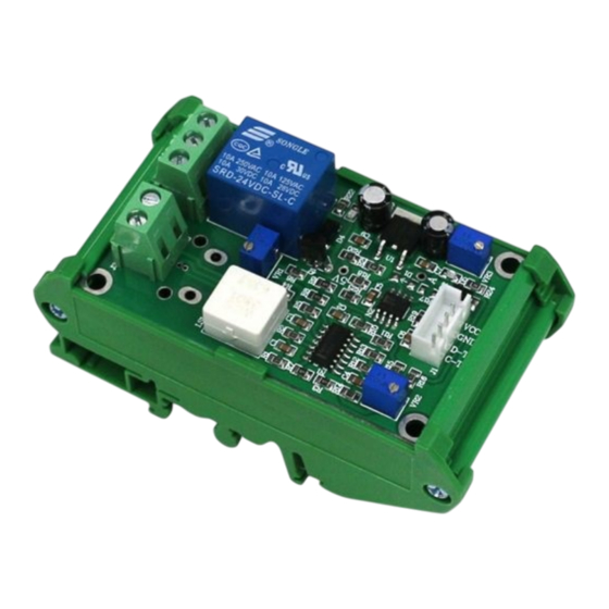
LINEAR DC SENSOR & OVER-CURRENT PROTECTOR
User Guide for SRCN-C03A
Product Description
This module is used to measure and monitor current consumption by utilizing hall-effect technology. A voltage output is produced in direct proportion
to the measured current. If the current exceeds a preset value, the relay on the module is activated. Uses include building automation and facility
management systems, where acquiring information on energy usage can lead to increased efficiency. They can also detect equipment issues and
help prevent damage by detecting over-current and/or short-circuit conditions.
Features
Hall-effect technology
Low power consumption
Analog signal and relay outputs
35 mm DIN rail or panel mountable
Applications
Building and facilities management
HVAC
Electric fans
Electric pumps
Devices requiring over-current & short-circuit protection
Thank you for choosing L-com product. To ensure safe, accurate performance and product longevity, please take a moment to familiarize yourself
with this manual before powering the device. Please keep it handy for future reference. In case of any questions regarding the installation or use of
product, please call us at 800.341.5266.
Reach out to us at customerservice@l-com.com and visit our website at www.l-com.com
1
Advertisement
Table of Contents

Related Manuals for Infinite L-com SRCN-C03A


Summary of Contents for Infinite L-com SRCN-C03A
- Page 1 LINEAR DC SENSOR & OVER-CURRENT PROTECTOR User Guide for SRCN-C03A Product Description This module is used to measure and monitor current consumption by utilizing hall-effect technology. A voltage output is produced in direct proportion to the measured current. If the current exceeds a preset value, the relay on the module is activated. Uses include building automation and facility management systems, where acquiring information on energy usage can lead to increased efficiency.
- Page 2 Technical Parameters Working voltage 12 VDC ± 0.5 VDC 6 8 mA Standby Working current Relay operation 12 V @ 60 mA 0 70 °C Working temperature 10 90% (No condensation) Working humidity 0 1 A (Max ± 0.02 A) Detection range (error) Analog signal 0 ...
- Page 3 Mounting Diagram 35mm DIN rail mounting: Mount the sensor module onto the DIN rail (dark black) as shown in the figure. Board Mount Mount the PCB to the enclosure with screws. Mounting hole diameter is 3mm. Correction Method After the module is powered ON, measure voltage value of the positive end of C1. Then adjust the VR1 potentiometer to make the positive end of C3 of same voltage value as C1, the zero adjustment is completed.
Need help?
Do you have a question about the L-com SRCN-C03A and is the answer not in the manual?
Questions and answers