
Related Manuals for AMS AS5147P


Summary of Contents for AMS AS5147P
- Page 1 Eval Kit Manual DN[Document ID] AS5147P Adapter Board AS5147P-TS_EK_AB ams Eval Kit Manual, Confidential Page 1 [v1-0] 2015-Jan-14 Document Feedback...
-
Page 2: Table Of Contents
Table of Contents Introduction .......................... 3 Kit Content ........................... 3 Board description ......................... 4 Mounting the AS5147P adapter board................. 5 AS5147P adapter board and pinout..................6 Operation case ........................7 One device SPI mode, unidirectional – 3 wire ..............7 One device SPI mode, bidirectional –... -
Page 3: Introduction
AS5147P Adapter Board Introduction The AS5147P adapter board is a small PCB allowing simple and quick testing or evaluation of the AS5147P magnetic position sensor without the need to build a test fixture or design an own PCB. Kit Content Figure 1: Kit content Pos. -
Page 4: Board Description
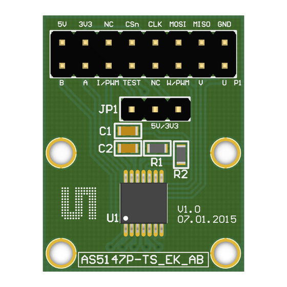
R1 and R2 are 0 ohm resistors in 0603 package. Depending on the supply voltage either R1 or R2 has to be populated. For 5V operation R1 has to be populated and R2 has to be removed (default case). Vice versa for 3.3V operation. Figure 2: AS5147P adapter board P1 connector (Not populated) -
Page 5: Mounting The As5147P Adapter Board
5V/3V3 AS5147P A 6x2.5mm diametric magnet must be placed over or under the AS5147P sensor, and should be centered on the middle of the package with a tolerance of 0.5mm. The airgap between the magnet surface and the package should be maintained in the range 0.5mm to 3mm. The magnet holder must not be ferromagnetic. -
Page 6: As5147P Adapter Board And Pinout
AS5147P Adapter Board AS5147P adapter board and pinout Figure 4: AS5147P adapter board and sensor pinout MOSI MISO I/PWM I/PWM TEST W/PWM MISO VDD3V 5V/3V3 MOSI TEST AS5147P W/PWM Pin# Pin# Symbol board Type Description Board AS5147P P1 - 1... -
Page 7: Operation Case
The minimum connection requirements for unidirectional communication between the microcontroller and the AS5147P are MISO, CLK, CSn. In this case the MOSI pin is tied to VDD which will result in reading only the 14-bit Angle Register (0x3FFF). See AS5147P datasheet register table, register 0x3FFF. -
Page 8: One Device Spi Mode, Bidirectional - 4 Wire
One device SPI mode, bidirectional – 4 wire If it’s needed to read other registers than the Angle Register (0x3FFF) or to write to registers of the AS5147P the MOSI connection is required. Figure 6: One device SPI mode, bidirectional – 4 wire 3-3.6V... -
Page 9: As5147P-Ts_Ek_Ab Hardware
AS5147P Adapter Board AS5147P-TS_EK_AB Hardware AS5147P-TS_EK_AB schematics Figure 7: AS5147P-TS_EK_AB schematics ams Eval Kit Manual, Confidential Page 9 [v1-0] 2015-Jan-14 Document Feedback... -
Page 10: As5147P-Ts_Ek_Ab Pcb Layout
AS5147P Adapter Board AS5147P-TS_EK_AB PCB layout Figure 8: AS5147P-TS_EK_AB PCB layout ams Eval Kit Manual, Confidential Page 10 [v1-0] 2015-Jan-14 Document Feedback... -
Page 11: Ordering & Contact Information
AS5147P Adapter Board Ordering & Contact Information Ordering Code Description AS5147P-TS_EK_AB AS5147P Eval Kit Adapter Board Buy our products or get free samples online at: www.ams.com/ICdirect Technical Support is available at: www.ams.com/Technical-Support Provide feedback about this document at: www.ams.com/Document-Feedback For further information and requests, e-mail us at: ams_sales@ams.com... -
Page 12: Copyrights & Disclaimer
AG shall not be liable to recipient or any third party for any damages, including but not limited to personal injury, property damage, loss of profits, loss of use, interruption of business or indirect, special, incidental or consequential damages, of any kind, in connection with or arising out of the furnishing, performance or use of the technical data herein. - Page 13 Mouser Electronics Authorized Distributor Click to View Pricing, Inventory, Delivery & Lifecycle Information: AS5147P-TS_EK_AB...
Need help?
Do you have a question about the AS5147P and is the answer not in the manual?
Questions and answers