Table of Contents
Advertisement
Quick Links
It is imperative to read the operating instructions prior
to commissioning!
Th is document as well as all documents included in the
appendix is not subject to any update service!
Subject to technical changes.
Issue:
01/2014
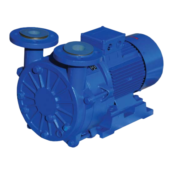
Operating Instructions
SM30B - SM250B
Motor Mounted
Liquid Ring Vacuum Pumps
Doc./ Item no.:
255548 Rev.1
Advertisement
Table of Contents

Summary of Contents for Ohio Medical Corporation SM30B
- Page 1 Operating Instructions SM30B - SM250B Motor Mounted Liquid Ring Vacuum Pumps It is imperative to read the operating instructions prior to commissioning! Th is document as well as all documents included in the appendix is not subject to any update service! Subject to technical changes.
-
Page 2: Table Of Contents
5.1.3 Preparing installation site ..........14 7.5 Assembly ................23 5.1.4 Preparing foundation and surface ......14 7.5.2 Assembly of SM30B ............23 5.1.5 Removing preserving agent ......... 14 7.5.3 Assembly of SM55-250B ..........24 5.2 Set-up with foundation ............ 14 5.2.1 Placing aggregate on foundation ......... - Page 3 8 Troubleshooting ..............26 10 Appendix ................32 10.3 Dimensional drawing SM30B........32 9 Technical data ..............28 10.4 Cross-sectional drawing SM30B ........33 9.1 Operating limits ............... 28 10.5 Dimensional drawing SM55-100B ....... 34 9.1.1 Media to be pumped ............. 28 10.6 Cross-sectional drawing SM55-SM75B ......
-
Page 4: Important Basic Information
1 Important basic information Technical support address Th ese operating instructions form part of the technical Ohio Medical Corporation Documentation of the system in accordance with the EC 1111 Lakeside Drive machinery directive. Gurnee, IL 60031 800-448-0770 Th ese operating instructions comply with machinery servicedept@ohiomedical.com... -
Page 5: Target Groups
1.1 Target groups Target Group Task ▶ Keep these instructions available at the location of the system, also for later Operator consultation. ▶ Advise staff to read and observe these instructions and the provided documents, particularly the safety precautions and warnings. ▶... -
Page 6: Warnings And Symbols
1.3 Warnings and symbols Warning Security level Consequences of non-observances D A N G E R imminently hazardous situation death, severe personal injuries potentially hazardous situation death, severe personal injuries WA R N I N G potentially dangerous situation minor personal injuries ... -
Page 7: Safety
2 Safety • When delivering solid laden liquids, observe the solid content limit values (→ General technical data, page 28). Th e manufacturer does not accept liability for • Do not combine multiple limit values (→ Operating damage resulting from non-observance of the overall limits, page 28). -
Page 8: Obligations Of The Operator
2.3.3 Obligations of the staff 2.3.2 Obligations of the operator • Notes attached to the aggregate must be observed and 2.3.2.1 Safety-conscious working kept legible, e.g. arrows indicating the direction of • Only operate the aggregate in a technically fl awless rotation, symbols indicating fl uid connections. -
Page 9: Design And Functioning
3 Design and functioning 3.1.3 Pump type code 3.1 Marking 3.1.1 Nameplate 1. Series 2. Size 3. Material design code Tab. 6 Pump type code (example) 3.2 General description Th e pumps of the SM series are horizontal, single-stage liquid ring vacuum pumps with radial inlet and outlet. Th e internal control of the gas to be pumped is realized by means of inter casings (1) with control slots and additional 1. -
Page 10: Design And Functional Principle
3.4 Shaft sealing 3.3 Design and functional principle 3.4.1 Mechanical seal Th e pump is operated in accordance with the liquid ring principle. Th e impeller is positioned off -center in the Mechanical seals may slightly leak for functional reasons. cylindrical pump casing. -
Page 11: Transport, Storage And Disposal
4.1.3 Transport with lift ing gear 4 Transport, storage and disposal Th e following accident prevention regulations have to D A N G E R be observed prior to following transport and handling regulations: Risk of death or contusions from falling goods to be −... -
Page 12: Preservation
• Plug all drainage bores with screw plugs. C AU T I O N • Remove the pipes from the suction, pressure and process water connections. Risk of material damage caused by improper storage! • Plug the outlet nozzle and the process water connection ▶... -
Page 13: Removing Preserving Agent
• Continue with this process until no more preserving 4.5 Disposal agent escapes. WA R N I N G • Close the suction, pressure and operating liquid connection (UB) using transport or sealing covers. Risk of intoxication and environmental damage caused •... -
Page 14: Set-Up And Connection
5.1.5 Removing preserving agent 5 Set-up and connection ▶ If the aggregate is commissioned directly aft er set-up For aggregates in potentially explosive areas (→ ATEX additional instructions) and connection: remove preserving agent prior to set- up (→ Removing preserving agent, page 13). C AU T I O N 5.2 Set-up with foundation ... -
Page 15: Fixing Aggregate
5.2.2 Fixing aggregate 5.4 Set-up on level surface/frame Filling the base plate with mortar grout improves the Only possible with motor feet dampening behaviour. ✓ Auxiliary means, tools, material: 1. Fill the anchoring holes with mortar grout. − wrench 2. -
Page 16: Specifying Nominal Diameter
5.5.2 Specifying nominal diameter 2. Make sure no fl ange seals project inwards. Size of suction/pressure connections (→ Operating 3. Make sure no sealing material (sealing tape, adhesive) connections, page 29) projects inwards. ▶ Keep the fl ow resistance in the pipes as low as possible. 4. -
Page 17: Motor Connection
5.7.1 Motor connection 6 Operation Observe the manufacturer’s specifi cations for the motor. For aggregates in potentially explosive areas (→ ATEX additional instructions) 1. Connect the motor in accordance with the circuit diagram. 6.1 Preparations for commissioning 2. Exclude any risk associated with electric power. 6.1.1 Identifying pump type 3. -
Page 18: Switch-Off
5. Open the suction-side fi tting. R I S K O F E L E C T R I C S H O C K 6. Ventilation port (if available): close the fi tting as soon as the motor has reached its nominal speed. Risk of death from electric shock! 7. -
Page 19: Open Circulation Cooling
6.3.2 Open circulation cooling 6.3.3 Closed circulation cooling ▶ Switch on the aggregate. ▶ Switch on the aggregate. ▶ Set the pressure in the operating liquid pipe to max. 0.2 ▶ Set the pressure in the operating liquid pipe to a value bar overpressure (→... -
Page 20: Re-Commissioning
6.6 Operating stand-by aggregate ▶ Implement the following measures when taking the pump/aggregate out of operation: ✓ Stand-by aggregate fi lled Operate the stand-by aggregate at least once per week. Aggregate is Measure 7 Maintenance and servicing Shortly operate (approx. 5 shut down while minutes) the aggregate at ... -
Page 21: Rinsing Off Contaminations
− free and clean fi lters 7.4 Disassembly − no unusual running noise or vibrations D A N G E R − no impermissible leaks at the shaft sealing Risk of injuries caused by running aggregate! − proper functioning of the auxiliary operating systems ▶... -
Page 22: Spare Parts
3. Install the aggregate into the system (→ Set-up and connection, page 14). − Loosen the screw plug (903) on the pump casing (101) (only SM100B). 7.4.5 Disassembly of SM30B − Loosen the hexagon socket head screw (914) (only Cross-sectional drawing (→ page 33) SM100B). -
Page 23: Assembly
Rotate the impeller screw (906, hexagon socket wrench) until a gap of 0.1 to 0.15 mm remains Cross-sectional drawing SM30B (→ page 33) between the straightedge and the impeller hub. ✓ All parts are in a clean and level assembly area. -
Page 24: Assembly Of Sm55-250B
− Adjust the pump casing (101) (inlet/outlet nozzle − Apply a thin layer of grease (Molykote®) to the motor opposite the motor feet). shaft . − Put the pump casing (101) down on the inter casing. − Push the impeller (230) onto the motor shaft . −... - Page 25 7. Installation of pump casing (101) − Insert an O-ring (412) into the groove of the shaft sealing casing (441). − Adjust the pump casing (101) (inlet/outlet nozzle opposite the motor feet). − Force the pump casing (101) into the shaft sealing casing (441).
-
Page 26: Troubleshooting
8 Troubleshooting D A N G E R Risk of injuries caused by running aggregate! ▶ Do not touch the running aggregate. ▶ Do not carry out any works on the running aggregate. ▶ Prior to carrying out any assembly or maintenance works, de-energize the motor and protect it against restart. ... - Page 27 Defect Cause Solution Excessive Motor overload ▶ Check/reduce the operating liquid fl ow rate power Excessive backpressure in the outlet nozzle ▶ Reduce backpressure consumption Excessive share of liquid in the suction fl ow ▶ Reduce the share of liquid of the motor Blocked suction-side fi tting ▶...
-
Page 28: Technical Data
Temperature Max. Type pressure level L [db(A)]* 60 Hz Saturated Speed SM30B 3500 SM55B Tab. 12 Operating limits SM30B SM75B SM100B SM55, 75, 100, 200, 250B SM200B Pressure Operating Liquid (water) SM250B Min. Inlet Temperature Pressure * Measured surface sound pressure level in acc. with DIN... -
Page 29: Operating Liquid
Risk of material damage caused by corrosion and of the shaft deposits in the pump due to poor water quality! [QT] ▶ If possible, use operating water featuring the following SM30B quality. SM55B Th e following recommendations apply to operating SM75B water temperatures <... -
Page 30: Ambient Conditions
Min. clearance Type fan hood - adjacent surface M 16 A2/ A4 [mm] Tab. 27 Tightening torques for stainless steel screws in SM30B 1.4” stainless steel casings SM55/75B 9.2.10.4 Screw plugs SM100B 2.2” Th e following values apply to new screw plugs... -
Page 31: Conical Pipe Fi Ttings
Type Filling volume Filling volume cast-iron casings (EN-GJL-250, CuZn). inside system outside system [QT] [QT] Size Tightening torque [Nm] SM30B approx. 0.6 G 1/4 A SM55B approx. 5.8 G 3/8 A SM75B approx. 6.3 G 1/2 A SM100B approx. 8.5... -
Page 32: Appendix
(Dimensional drawings) • Spare parts designation and position (cross- sectional drawings) • Certifi cate of conformity • EC declaration of conformity 10.3 Dimensional drawing SM30B Fig. 16 Dimensional drawing SM30B MOTOR MODEL HA HD SIZE SM30B 50/60 6.7" .2" 4.3" 2.9" 6.9" 16.1" 14.8" 5.5" 6.7" 4.9" 6.1" 2.2" 3.5"... -
Page 33: Cross-Sectional Drawing Sm30B
550/.1,550.3 Washer 561/.1 Grooved pin Steel sheet Valve fl ap Motor 901/.1 Hexagon head screw Stud bolt 903/.1 Screw plug Impeller screw 920/.1 Hexagon nut Disc spring Nameplate Tab. 39 Parts list SM30B Fig. 17 Cross-sectional drawing SM30B 255548 Rev.1... -
Page 34: Dimensional Drawing Sm55-100B
10.5 Dimensional drawing SM55B/SM75B/SM100B Fig. 18 Dimensional drawing SM55B/SM75B/SM100B MOTOR MODEL SIZE SM55B 50/60 100L 10.8" 12.9" 2.5" 11" 7.1" 7.9" 20.3" 17.4" 6.3" 7.7" 5.5" 7.0" 2.5" 4.0" .5" 10" 12" SM75B 50/60 112M 11.3" 12.9" 2.5" 11" 7.1" 8.9"... -
Page 35: Cross-Sectional Drawing Sm55-Sm75B
10.6 Cross-sectional drawing SM55B/SM75B Designation Mechanical seal Pump casing Inter casing Impeller 411/.1 Sealing ring O-ring Shaft sealing casing 550/.1 Washer 561/.1 Grooved pin Steel sheet Valve fl ap Motor Screw 901/.1,901.3 Hexagon head screw 903/.1 Screw plug Impeller screw 920/.1 Hexagon nut Disc spring... -
Page 36: Cross-Sectional Drawing Sm100B
10.7 Cross-sectional drawing SM100B Designation Mechanical seal Pump casing Inter casing Impeller 411/.1 Sealing ring O-ring Shaft sealing casing 550/.1 Washer 561/.1 Grooved pin Steel sheet Valve fl ap Motor 901-.2 Hexagon head screw 903/.1 Screw plug Th readed pin Impeller screw Screw Hexagon nut... -
Page 37: Dimensional Drawing Sm200B-250B
10.8 Dimensional drawing SM200B/SM250B Fig. 21 Dimensional drawing SM200B/SM250B MODEL MOTOR 132M 13.9" 12" 28.8" 28.8" 8.5" 10.1" 7" 8.6" 3.8" 5.2" .7" 12.6" .5" 17" SM200B 160M 14.2" 12.2" 28.3" 28.3" 10" 12.6" 8.3" 10.2" 4.1" 6.3" .9" 16.2" .6"... -
Page 38: Cross-Sectional Drawing Sm200B-250B
10.9 Cross-sectional drawing SM200B/SM250B Designation Mechanical seal Pump casing Inter casing Impeller Flat gasket Sealing ring O-ring Shaft sealing casing 550/.1 Washer 561/.1 Grooved pin Steel sheet Th readed fl ange Valve fl ap Motor Screw 901-.3 Hexagon head screw Stud bolt Fig. -
Page 39: Certifi Cate Of Conformity
10.17 Certifi cate of conformity Please copy this form and return it to the manufacturer together with the pump/aggregate. Certifi cate of conformity Th e pump/pump aggregate including accessories for which we, the undersigned, have placed an inspection/repair order or which has been returned by us together with this certifi cate of conformity, Designation: _____________________________________________________________________________... - Page 40 © 2014 Ohio Medical Corporation. Th is document contains information that is proprietary and confi dential to Ohio Medical Corporation. Use of this information is under license from Ohio Medical Corporation. Any use other than that authorized by Ohio Medical Corporation is prohibited.
Need help?
Do you have a question about the SM30B and is the answer not in the manual?
Questions and answers