Table of Contents
Advertisement
Quick Links
Advertisement
Table of Contents

Related Manuals for Kirchner und Tochter KLA


Summary of Contents for Kirchner und Tochter KLA
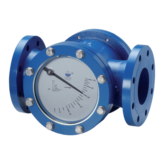
- Page 1 Assembly and operating Instructions FLAP-type Flow Meter KLA-GS KLA-V4A KLA-IK KLA-IKS KLA-EM A. Kirchner & Tochter GmbH Dieselstraße 17 · D-47228 Duisburg Fon: +49 2065 9609-0 · Fax: +49 2065 9609-22 Internet: www.kt-flow.de · e-mail: info@kt-flow.de Version 3.1...
-
Page 2: Table Of Contents
Information for Operator and operating personnel ........4 Regulations and guidelines ................4 Notice as required by the hazardous materials directive ......5 Transport and storage ....................5 Installation ......................6 Mounting position KLA .................6 Installation KLA .....................7 Start-up ........................8 Readings in operation ....................8 Limit switches ......................9 Connection of limit switches .................9... -
Page 3: Foreword
Foreword These Installation and Operating Instructions are applicable to devices of series KLA. Please follow all instructions and information given for installation, operation, inspection and maintenance. The Instructions form a component part of the device and should be kept in an appropriate place accessible to the personnel in the vicinity of the location. -
Page 4: Intended Use
Intended use The KLA Series device is a flap-type VA flow meter for fluids. It is designed for installation in horizontal or vertical pipe runs. In vertical pipe runs, flow through the device must be from below. Installation in the pipeline may only be carried out in accordance with these Instructions. -
Page 5: Notice As Required By The Hazardous Materials Directive
In accordance with the law concerning handling of waste (critical waste) and the hazardous materials directive (general duty to protect), we would point out that all flow meters returned to Kirchner und Tochter for repair are required to be free from any and all hazardous substances (alkaline solutions, acids, solvents etc.). -
Page 6: Installation
In vertical pipe runs, flow must be from bottom to top. Make sure the pipes are correctly spaced and in true alignment at the installation location for the flow meter. For connection of the KLA device, fit the open ends of the pipeline at the installation point with flanges appropriate to the flow meter. -
Page 7: Installation Kla
The scale faces upwards/downwards. Figure 2 Installation KLA For mounting, provide the connection flanges of the KLA with suitable flat gaskets. The gaskets are not included with the flow meter. Before installing, remove the transport lock from inside the device and fit the open pipe ends with appropriate connecting flanges. -
Page 8: Start-Up
On the standard device, values are read off at the pointer on the aluminium scale. On the KLA GS version, the flow rate is indicated directly by the flap. At the front and rear, the flow meter features in each case a pane of hard glass. -
Page 9: Limit Switches
The switches have a bistable characteristic. The following devices are equipped with limit switches: KLA Standard-IK with BI1-HS540-Y1 - 2-Wire, NAMUR KLA Standard-IKS with BI1-HS540-AP6X - 3-Wire, PNP, NO KLA V4A-IK with BI1-HS540-Y1 - 2-Wire, NAMUR KLA V4A-IKS... -
Page 10: Setting The Limit Switches
Setting the limit switches The KLA is adjusted during factory assembly to the customer-specific switching points. If a new setting is required, the switching point can be changed by moving the pointer vane. The switching function can be reversed by specifying whether the pointer vane first enters or first exits the slot sensor. -
Page 11: Installation Of The Polycarbonate Protective Screen
7.2.4 Installation of the polycarbonate protective screen After successful adjustment of the limit switches, you must install the polycarbonate screen again. 1. Insert the O-ring into the corresponding groove. 2. Put the polycarbonate screen back in. Make sure that the O-ring does not slip out of its groove. -
Page 12: Analogue Output Em
A linearization is possible at up to 14 points. Furthermore various input and output filters ensure operation in industrial environments. The following devices are equipped with limit an analogue output: KLA Standard-EM with WPG NG100-L KLA-V4A-EM with WPG NG100-L Functional principle... -
Page 13: Maintenance And Cleaning Of The Low Meter
Before you start maintenance/cleaning, make sure that the medium line is shut off resp. emptied. The KLA can be opened from the back. Undo the fastening screws on the rear cover and take the cover off. Remove any dirt and deposits that may have accumulated in the casing and on the flap. -
Page 14: Technical Data
Soda lime glass, optionally Borosilicate glass Degree of protection in conformity with IP 54, switches: IP 53 The medium to be measured must not freeze. KLA-IK resp. KLA-IKS max. 70°C other connection geometries on request A. Kirchner & Tochter GmbH Dieselstraße 17 · D-47228 Duisburg Fon: +49 2065 9609-0 ·... -
Page 15: Materials
15 – 25 EN-GJL-200 glass KLA-GS-V4A Stainless steel Borosilicate 1.4571 1.4571 1.4571 25 – 100 1.4571, welded glass KLA rubber lined design Gray cast iron EN-GJL-200/S355 EN-GJL-200 1.4571 1.4571 1.4571 Sil-C8200 32 – 150 rubber lined rubber lined Gray cast iron... -
Page 16: Measuring Ranges
11.2 Measuring ranges measuring range H measuring range H max. operating pressure [bar] horizontal flow vertical flow standard version KLA-GS – m³/h – m³/h – m³/h – m³/h – m³/h – m³/h – m³/h – m³/h – m³/h – m³/h –... -
Page 17: Dimensions And Weights
11.3 Dimensions and weights 11.3.1 Flange connection acc. EN 1092-1 PN10 Dimensions Ø D Ø k Ø d Ø H L Ø D number of standard / weight screws [kg] 45 18 170 119 M12 4 20 105 58 18 170 119 M12 4 68 18 170 119 Ø... -
Page 18: 11.3.2 Flange Connection Acc. Asme B16.5 Class 150Lbs
11.3.2 Flange connection acc. ASME B16.5 class 150lbs Dimensions NPS Ø DN Ø D Ø k Ø d Ø H L Ø D number standard/ GS EM weight of screws [kg] “ 60,3 34,9 18 170 119 1/2“ * 132 166 ½... -
Page 19: Type Series
11.5 Technical data of limit switches The following devices are equipped with limit switches: KLA Standard-IK with BI1-HS540-Y1 - 2-Wire, NAMUR KLA Standard-IKS with BI1-HS540-AP6X - 3-Wire, PNP, NO KLA V4A-IK with BI1-HS540-Y1 - 2-Wire, NAMUR KLA V4A-IKS with BI1-HS540-AP6X - 3-Wire, PNP, NO... - Page 20 3-wire (BI1-HS540-AP6X) Features adjustable, bistable Switching function Normally closed, normally open Output function Three-wire, PNP Operating voltage 10 ... 30 V DC Repeatability ≤ 2 % f.s. Temperature drift ≤ ± 10 % Hysteresis 3 ... 15 % DC Rated operational current ≤...
-
Page 21: Analogue Output Em
11.6 Analogue output EM 4 ... 20 mA Operating voltage (Ub) 12 ... 36 V DC Accuracy ± 1 % Temperature drift ± 0,005 % /K Temperature resistance -20 ... +70 °C 300 Ω at U = 24 V Load impedance 50 Ω... - Page 22 Notes A. Kirchner & Tochter GmbH Dieselstraße 17 · D-47228 Duisburg Fon: +49 2065 9609-0 · Fax: +49 2065 9609-22 Internet: www.kt-flow.de · e-mail: info@kt-flow.de -22- Version 3.1...
- Page 23 Notes A. Kirchner & Tochter GmbH Dieselstraße 17 · D-47228 Duisburg Fon: +49 2065 9609-0 · Fax: +49 2065 9609-22 Internet: www.kt-flow.de · e-mail: info@kt-flow.de -23- Version 3.1...
- Page 24 The devices from Kirchner und Tochter have been tested in compliance with applicable EC/EU CE-regulations of the European Community. The respective declaration of conformity is available on request. Subject to change without notice. The current valid version of our documents can be found at www.kt-flow.de.
Need help?
Do you have a question about the KLA and is the answer not in the manual?
Questions and answers