Table of Contents
Advertisement
Quick Links
Advertisement
Table of Contents

Related Manuals for Kirchner und Tochter RA 77


Summary of Contents for Kirchner und Tochter RA 77
- Page 1 VA Flow Meters RA 77 / FA 77 Installation and Operating Instructions Variable area flow meter RA 77 / FA 77 A. Kirchner & Tochter GmbH Dieselstraße 17 · D-47228 Duisburg Fon: +49 2065 9609-0 · Fax: +49 2065 9609-22 Internet: www.kt-web.de · e-mail: info@kt-web.de...
-
Page 2: Table Of Contents
VA Flow Meters RA 77 / FA 77 Contents Foreword.................................. 3 Safety..................................3 2.1. Symbol and meaning..........................3 2.2. General safety directions and exemption from liability............3 2.3. Special safety instructions concerning glass devices.............. 3 2.4. Intended use ..............................4 2.5. -
Page 3: Foreword
Failure to comply with these instructions can lead to hazardous situations for Man and Beast and also to damage to property, for which Kirchner und Tochter disclaims all liability. The Operator is required to rule out potentially hazardous situations through voltage and released media energy. -
Page 4: Intended Use
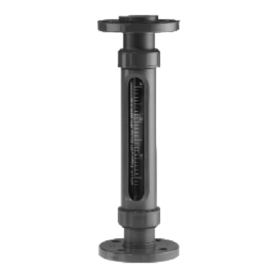
RA 77 / FA 77 2.4. Intended use The RA 77/FA 77 Series device is a variable-area flow meter for liquids and gases. It is designed for installation in vertical pipe runs. Installation in the pipeline should be carried out solely in accordance with these Instructions. The required version of the variable-area flowmeter should be selected on the basis of the pipe diameter at the installation location of the device. -
Page 5: Installation
Clean by blowing out or flushing the pipes leading to the device before connecting Prepare the installation point with the appropriate pipe (RA 77) or flange connection (FA 77) before starting to fit the flow meter. Make sure sealing faces are correctly spaced apart and in true alignment. -
Page 6: Installing The Fa 77
VA Flow Meters RA 77 / FA 77 4.3. Installing the FA 77 Slide the device together with the flat gaskets (not included with the flow meter) at both ends into the installation point. Check that the flat gaskets are in alignment and that they do not project into the pipeline. -
Page 7: Limit Contacts Msk1, Msk12, Mskw
VA Flow Meters RA 77 / FA 77 Limit contacts MSK1, MSK12, MSKW The flow meter can be equipped with limit contacts to provide local indication with monitoring function. The limit contacts consist of a limit contact (reed switch) that is switched over by the magnet integrated in the float. -
Page 8: Maintenance And Cleaning Of Ra77/Fa77
VA Flow Meters RA 77 / FA 77 Maintenance and cleaning of RA77/FA77 The flow meter is maintenance-free. Should the glass cone become fouled, the meter can be removed from the pipeline as follows. 8.1. Dismantling and assembly Remove the flow meter from the system by detaching the union nuts or the screw connections and/or pipe unions, as the case may be. -
Page 9: Technical Data
VA Flow Meters RA 77 / FA 77 10. Technical data Nominal pressure PVC: PN 10 at 0 to +20°C/max 6 bar rating at 40°C and temperature PP: PN 10 at 0 to +20°C/max 1,5 bar resistance of the at 80°C device PVDF: PN 10 at 0 to +20°C/max 5,5 bar... -
Page 10: Dimensions
VA Flow Meters RA 77 / FA 77 10.1. Dimensions RA 77 Size Glued 1 1/2 1/2 3/4 2 1/4 1 1/4 1 1/4 2 3/4 1 1/2 1 1/2 3 1/2 4 1/2 2 1/2 Union nut: Aluminium hexagonal... -
Page 11: Technical Data Of Limit Contacts
VA Flow Meters RA 77 / FA 77 10.2. Technical data of limit contacts Design MSK1 MSK12 Voltage switched 50VAC/75VDC 50VAC/75VDC Current switched 0,5A 0,5A Contact rating 10W/VA 10W/VA Dielectric strength 230VAC/400VDC 230VAC/400VDC Temperature range -20 bis +90°C -20 bis +90°C... - Page 12 CE-regulations of the European Community. The respective declaration of conformity is available on request. The Kirchner und Tochter QM-System will be certified in accordance with DIN-EN-ISO 9001:2000. The quality is systematically adapted to the increasing demands.
Need help?
Do you have a question about the RA 77 and is the answer not in the manual?
Questions and answers