
Subscribe to Our Youtube Channel
Related Manuals for Standart SDS-UL


Summary of Contents for Standart SDS-UL
- Page 1 Instruction for Operation and Maintenance SDS - UL/FM Double Suction Split Case Centrifugal Fire Pumps...
- Page 2 Instructions for Installation, Operation and Maintenance Standart Pompa ve Makina San. Tic. A.Ş. All rights reserved. Can not be copied or reproduced for any purpose without permission. Subject in the manual can be changed without any prior notice. 05.2019 Revision 1...
-
Page 3: Table Of Contents
Contents 1. GENERAL 1.1 Safety Signs 1.2 General Instructions 1.3 Safety Instructions 1.3.1 CE signs and approvals 1.3.2 Personnel qualification and training 1.4 Recycling 2. GENERAL PUMP DESCRIPTION 2.1 Pump Description 2.2 Application Areas 2.3 Pump Designation 2.4 Pump Nameplate 2.5 Technical Information 3. - Page 4 Contents 5. START UP / SHUT DOWN 5.1 Preparation 5.1.1 Lubrication Control 5.1.2 Venting and priming 5.1.3 Checking the direction of rotation 5.2 Start Up The Pump 5.3 Checks to be Made While The Pump is Running 6. LUBRICATION 6.1 Application of Grease on the Bearing 7.
-
Page 5: General
• Standart Pompa does not accept any responsibility under warranty for any repair or replacement performed by the user or any other unauthorized persons. -
Page 6: Ce Signs And Approvals
Recycling For products and arts which will not be used and scraped, use the local or private waste collection services. If it is not possible, consult the nearest authorized service centre of STANDART POMPA. -
Page 7: General Pump Description
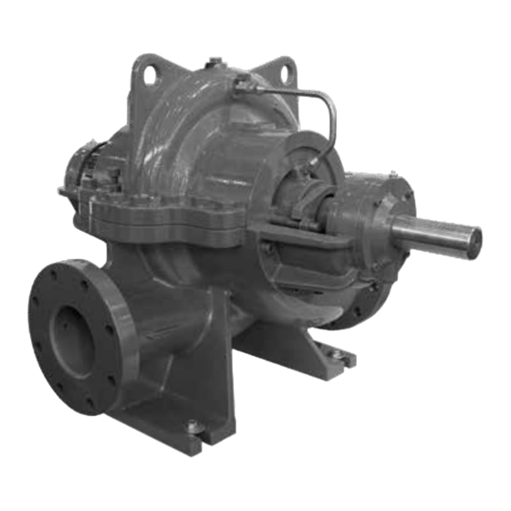
SDS PUMPS 2- GENERAL PUMP DESCRIPTION 2.1- Pump Description • SDS series pumps are fire pumps which is designed in accordance with UL 448 and FM Class 1311 standards. 2.2- Application Areas SDS series pumps are suitable for clean or slightly contaminated (max. 20 mg/dm ) liquids with low viscosities. -
Page 8: Unpacking, Handling And Strage
• Remove unpackaged pump and accessories (if any) carefully. Check whether they have been damaged during transportation. • If any damage has occurred during transportation, notify SERVICE DEPARTMENT, STANDART POMPA and SHIPPING COMPANY about it immediately. • Check whether all materials in the shipping list have been delivered. If there is any missing article, advise SERVICE DEPARTMENT, STANDART POMPA. -
Page 9: Storage
3.3- Storage • If the pump will not be installed in place immediately, it should be stored at a clean and dry place free of any frost hazard without excessive change in the ambient temperature. • If the pump bearings are of grease-applied ones, extra grease should be applied to the bearings to prevent moisture ingress around the shaft. -
Page 10: General Characteristics Of The Pump Foundation (Baseplate)
4.3.1- General characteristics of the pump foundation (baseplate) You should work carefully for preparation of the pump base and installation of the pump group in place. Improper and careless installation may cause excessive vibration and premature ATTENTION wear of the pump equipment as well as pump failure. Baseplate Shim 20 - 40 mm... -
Page 11: Installation Of The Piping System
Volume ratio: Cement 1 : sand 1.5: gravel 3 Concrete hardens within 7 days (hardening time may be shortened by use of special cement). • Fixing of the frame on the foundation concrete mass exactly by adjustment. - The area about 30mm between the foundation concrete mass and frame is formed and concrete is poured through the holes in the frame. - Page 12 Piping Support Long Radius Elbow Isolating Valve Fig 3. Suction Head Allowable Forces and Moments on Flange Suction Flange Dischage Flange Pump ∑F ∑M ∑F ∑M Type [Nm] [Nm] [Nm] [Nm] [Nm] [Nm] [Nm] [Nm] 65-250 1690 1560 1430 2730 1020 1100 1690...
-
Page 13: Suction Pipe
4.4.2- Suction pipe • The suction pipe should be definitely watertight and should not be arranged in a way to cause formation of air pockets. Figure 3 • In order to keep the loss from friction, sharp elbows should not be used; and abrupt change of direction and section should be avoided and suction pipe should be made short as far as possible. -
Page 14: Coupling Adjustment
4.5- Coupling Adjustment After installation of the baseplate and system ATTENTION connections, the coupling adjustment should be controlled finally. The reason that proper adjustment of the entire system is responsibility of the purchaser. “Coupling Adjustment” is to ensure that the ATTENTION rotation axes of the motor and pump should be on the same plane. -
Page 15: Electrical Connections
• In order to control the parallelism mistake, a gauge with straight edge is pressed on a part of the coupling in parallel to the axis and the position of the gauge related to other part is observed. The gauge should contact with both two parts simultaneously and along its entire edge. This process should be performed at two opposite places on the horizontal and vertical plane (Figure 6c, 6d). -
Page 16: Final Controls
Motor Power Motor Power ≤ 4 kW > 4 kW Type of switch Power Supply Power Supply 3 ~ 400 V 3 ~ 400 V Y – connection (11b) direct ∆ – connection (11a) Y / ∆ - start Remove connection Impossible bridges (11c) Table 2... -
Page 17: Start Up / Shut Down
5- START UP / SHUT DOWN 5.1- Preparation 5.1.1- Lubrication control • The bearings of SDS type pump are always lifetime grease lubricated. Lifetime grease lubricated bearings are maintenance-free. 5.1.2- Venting and priming • Make sure that the pump and suction pipes are completely filled up with water. There is no problem for the pumps which have positive suction head. -
Page 18: Checks To Be Made While The Pump Is Running
5.3- Checks to be Made While The Pump is Running • The pump must never run dry. ATTENTION • Never run the pump for along period against a closed discharge valve (at zero flow) • The bearing temperature may exceed the ambient temperature by up to 50 ºC. But must never rise above 80 ºC. -
Page 19: Disasembly And Reassembly
7- DISASEMBLY AND REASSEMBLY • Follow the safety precaution measures outlined in “safety instructions”. 7.1- Disassembly • Close all valves in the suction and discharge lines, and drain the pump by opening the drain plug and the air plug. • Disconnect the stu ng boxes flushing pipes. •... -
Page 20: Shaft Seal
Table 6 8- SPARE PART • STANDART POMPA guarantees to supply the spare parts for SDS type pumps for 10 years. You can provide any spare parts easily. • Lets us know the following details on the name-plate, when you order spare parts. -
Page 21: Faults, Causes And Remedies
9- FAULTS, CAUSES AND REMEDIES In this section you will find operating faults which may arise, and their causes (Table 8), and suggested remedies (Table 9). FAULTS POSSIBLE CAUSES Pump does not deliver any water after start-up 1-5-7-10-11-13 Flow is going down or no flow at all 1-2-3-4-6-7-8-14 Driver overloaded 9-12-17-18-19-27-28... -
Page 22: Expected Noise Values
POSSIBLE CAUSES REMEDY METHODS Check mains voltage and frequency or whether there is phase faults Low speed in the engine Reduce the pump speed, if possible or machine the impeller diameter Speed too high according to the manufacturer’s recommendation. Impeller, check valve or strainer clogged Clean the impeller, check valve or strainer. -
Page 23: Sectional Drawing
11- SECTIONAL DRAWING... -
Page 24: Part List
12- PART LIST Part name Part name Part No Part No Stu ng Box (r ght s de) 003A Stu ng Box (left s de) O l Seal Volute Cas ng (top) Dra n Plug Volute Cas ng (bottom) N pple Wear R ng Grease N pple Bear ng Hous ng... - Page 25 EC DECLARATION OF CONFORMITY MANUFACTURER NAME: Standart Pompa ve Makina San. Tic. A.Ş. Dudullu Organize San. Bölgesi 2. Cad. No:9 34776 Ümraniye / İSTANBUL t: +90 216 466 89 00 f: +90 216 415 88 60 - www.standartpompa.com / info@standartpompa.com.tr The undersigned declares that the described products meet the essential requirements of the below mentioned standards as based on Machinery Directive 2006 / 42 / EC .
- Page 26 All rights reserved. Can not be copied or reproduced for any purpose without permission. Subject in the manual can be changed without any prior notice. Factory - Company Service www.standartpompa.com / info@standartpompa.com.tr...
Need help?
Do you have a question about the SDS-UL and is the answer not in the manual?
Questions and answers