Table of Contents
Advertisement
Advertisement
Table of Contents

Related Manuals for Standart SNL Series


Summary of Contents for Standart SNL Series
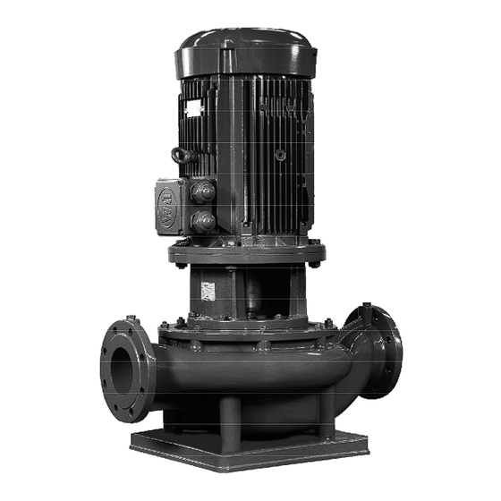
- Page 1 SNL IN LINE CENTRIFUGAL PUMPS INSTRUCTION for INSTALLATION, OPERATION & MAINTENANCE Pump Type : ....Serial No : ....Capacity : ....m³/h Head : ....m Motor Power : ....kW Speed : ....rpm BK SNL 00 10-12 EN...
- Page 2 Instructions for Installation, Operation and Maintenance Standart Pompa ve Makina San. Tic. A.Ş. All rights reserved. Can not be copied or reproduced for any purpose without permission. Subject in the manual can be changed without any prior notice.
-
Page 3: Table Of Contents
Contents CONTENTS IDENTIFICATION OF SAFETY AND WARNING SYMBOLS GENERAL INSTRUCTIONS SAFETY INSTRUCTIONS GENERAL A1- Pump Description A2- Applications A3- Pump Designation A4- Pump Nameplate A5- Technical Data UNCRATING, TRANSPORT AND STORAGE B1- Uncrating B2- Transport B2.1- General recommendations B2.2- Lifting B3- Storage INSTALLATION ON SITE C1- Preparation For Installation... - Page 4 DISASSEMBLY, REPAIR AND REASSEMBLY F1- Disassembly F2- Reassembly F3- Shaft Seal SPARE PARTS FAULTS, CAUSES AND REMEDIES TIGHTENING TORQUES EXPECTED NOISE VALUES PERMISSIBLE FORCES AND MOMENTS AT THE PUMP FLANGES PUMP DIMENSION GROUPS AND WEIGHTS SECTIONAL DRAWINGS (FOR MOTOR FRAME SIZE UP TO 200) SECTIONAL DRAWINGS (FOR MOTOR FRAME ABOVE 200) PERMISSIBLE INSTALLATION ARRANGEMENTS SAFETY GUARD...
-
Page 5: Identification Of Safety And Warning Symbols
The user is responsible for the verification of the ambient conditions where the pump will be stored or installed. - STANDART POMPA does not guarantee repairs or alterations done by user or other unauthorized personnel. The use of original spare parts and accessories authorized by manufacturer will ensure safety. -
Page 7: A- General
A2- Applications SNL series pumps are suitable for clean or slightly contaminated (max. 20 mg/dm³) liquids with low viscosities and temperatures up to 110 º C. The main application areas, among others, are Water supply systems, Warm water heating, chilled and cooling water systems. -
Page 8: B- Uncrating, Transport And Storage
Carefully remove the packaging material and check that pump and accessories (if any) are free from any markings, stretches and damages, which may have occurred during transportation. In the event of damage report this immediately to STANDART POMPA’s service department and to the transport company. -
Page 9: B3- Storage
B3- Storage If the pump is not to be installed and operated soon after arrival, store the pump in a clean, dry and frost- free place with moderate changes in ambient temperature. To prevent the pump from moisture, dust, dirt and foreign materials suitable steps should be taken. The pump shaft should be revolved periodically (e.g. -
Page 10: C4- Connection The Piping
C4- Connecting The Piping C4.1- General Never use the pump as an anchorage point or as a carrier for the piping. ATTENTION The pipes should be supported very near the pump (Fig. 3). It must be checked that any weight, stress or strains on the piping system should not be transmitted to the pump. -
Page 11: C4.3- Discharge Piping
C4.3- Discharge piping (Fig. 4) A control valve should be installed in the discharge pipe, as close to the pump as possible, to regulate the required flow and head. If the total head of the pump exceeds 10 meters or if discharge line is of appreciable length a non return valve should be installed between the pump and isolating valve on the discharge line to protect the pump against water hammer and reverse flow on shut down. -
Page 12: C4.6- Electrical Connections
C5.6- Electrical connections The electrical motors have to be built in accordance with EN 60034-1. Enclosures of electrical motors and control systems on the pump unit shall as a minimum give protection in accordance with EN 60529 IP22. But in determining the degree of protection of enclosures of electrical motors and control systems on the pump unit the operating and environmental conditions must be taken into consideration. -
Page 13: C4.7- Final Check
C5.7- Final check After completion all the above process rotate the pump rotor several times by hand. Make sure rotor rotates easily. Fix the safety guards back in places. Do not operate the pump before doing so. This is a necessity for security and job safety. -
Page 14: D4- Checks To Be Made While The Pump Is Running
D3- Shut Down The Pump Slowly close the shut-off valve in the discharge line. You may shut down the pump without closing the shut-off valve if there is a device for water hammer protection on the discharge line or the water hammer is not a considerable level. Switch off the driver. -
Page 15: F2- Reassembly
F2- Reassembly Reassembly proceeds in reverse sequence to disassembly as described in section F1. You may find the attached drawings useful (see sectional drawing in section M). Coat the seats and screw connections with graphite, silicon or similar slippery substance before reassembly. If you can not find any of the above you may use oil instead (except the pumps for drinking water). -
Page 16: G- Spare Parts
NOTE : See section L for pump dimension group G- SPARE PARTS STANDART POMPA guarantees to supply the spare parts for SNL type pumps for 10 years. You can provide any spare parts easily. Lets us know the following details on the name-plate, when you order spare parts. - Page 17 Table 6 REMEDIES POSSIBLE CAUSES Fill pump and suction pipe completely with liquid and repeat the priming There may be air existing in pump or procedure. suction pipe Check for leaks in suction pipe joints and fittings. Check shaft seal if Ingress of air through shaft seal, necessary increase the pressure of sealing liquid.
-
Page 18: I- Tightening Torques
I- TIGHTENING TORQUES Tightening Torques Tightening Torque max (N.m) Thread Diameter Property Classes 10.9 1050 1100 1550 2100 1450 1970 2770 3560 2530 J- EXPECTED NOISE VALUES Sound pressure level (dB Power of Motor (Pump with motor) (kW) 1450 rpm 2900 rpm <... -
Page 19: K- Permissible Forces And Moments At The Pump Flanges
K- PERMISSIBLE FORCES AND MOMENTS AT THE PUMP FLANGES F b M b Type 40-125 40-160 40-200 50-125 50-160 50-200 50-250 65-125 65-160 1200 65-200 65-250 65-315 80-125 80-160 1500 80-200 80-250 80-315 100-160 100-200 100-250 1100 1000 1300 2000 1100 100-315 100-400... -
Page 20: L- Pump Dimension Groups And Weights
L- PUMP DIMENSION GROUPS AND WEIGHTS 2900 rpm Dim. Weight Dim. Weight Pump Pump Motor Motor Group (kg) Group (kg) Type Type 160M 18.5 160L 40-125 65-250 180M 100L 200L 100L 200L 112M 40-160 112M 132S 132S 132S 112M 80-125 160M 132S 40-200... - Page 21 1450 rpm Pump Motor Weight Dim. Type (kg) Group 40-125 0.37 0.37 40-160 0.55 38,5 0.75 0.55 40-200 0.75 43,5 0.37 0.55 38,5 50-125 0.75 0.37 0.55 50-160 0.75 39,5 0.75 50-200 100L 50-250 100L 100L 0.37 0.55 65-125 0.75 42,5 46,5 0.75...
- Page 22 Dim. Pump Motor Weight Group Type (kg) 132S 132M 80-315 160M 160L 100-160 100L 100L 100L 112M 100-200 132S 132S 112M 132S 100-250 132M 160M 132M 160M 100-315 160L 18.5 180M 160L 18.5 180M 100-400 180L 200L 225S 100L 112M 125-200 132S 132M...
-
Page 23: M1- Sectional Drawings (For Motor Frame Size Up To 200)
M1- SECTIONAL DRAWINGS (FOR MOTOR FRAME SIZE UP TO 200) 021* 020* PART LIST Volute Casing Sepecer Sleve Base Plate Rigid Coupling Motor Pedestal Impeller Key *020 Wear Ring (Casing) Allen Bolt *021 Wear Ring (Casing Cover) Washer Casing Cover Set-Screw Impeller Mechanical Seal... -
Page 24: M2- Sectional Drawings (For Motor Frame Above 200)
M2- SECTIONAL DRAWINGS (FOR MOTOR FRAME ABOVE 200) 021* *020... -
Page 25: N- Permissible Installation Arrangements
N- PERMISSIBLE INSTALLATION ARRANGEMENTS A - B A - B A - B - C A - B Note : Letters A, B and C represent pump dimension groups (See section L for pump dimension groups). Fig. 10 O- SAFETY GUARDI Safety Guard Note: All guards are conforming to EN 294. - Page 26 EC DECLARATION OF CONFORMITY Products: Pumps of type SNL with motor Manufacturer: Standart Pompa ve Makina San. Tic. A.Ş. Organize San. Bölgesi 2. Cad. No:9 34775 Esenkent / Ümraniye / İSTANBUL / TURKEY t: +90 216 466 89 00 f: +90 216 499 05 59 www.standartpompa.com / info@standartpompa.com...
- Page 28 Factory - Center Service and Spare Parts Right reserved to change without notice. No responsibility is accepted because of printing errors.
Need help?
Do you have a question about the SNL Series and is the answer not in the manual?
Questions and answers