APT 320XAC Operation Manual
Modular ac power source
Hide thumbs
Also See for 320XAC:
- Operation manual (147 pages) ,
- Quick start manual (12 pages) ,
- Quick start manual (9 pages)

Subscribe to Our Youtube Channel
Related Manuals for APT 320XAC


Summary of Contents for APT 320XAC
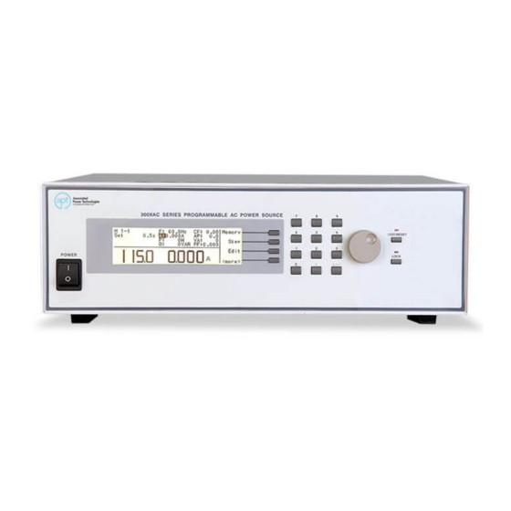
- Page 1 300XAC Series Modular AC Power Source Operation Manual for Models 310XAC 320XAC 340XAC 360XAC Ver. 1.24 PART # 39101...
- Page 2 Address: 28105 N. Keith Drive Lake Forest, IL 60045 USA Product Name: 300XAC Power Source Model Number: 310XAC, 320XAC Conforms to the following Standards: Safety: EN 61010-1:2010 EMC: EN 61326-1:2013 Class A EN 55011 :2009+A2 :2010 Group 1 Class A...
-
Page 3: Table Of Contents
Safety Precautions ................. 5 Service and Maintenance ............... 5 Getting Started ....................7 Unpacking and Inspection ..............7 Input/Output Power Considerations ............7 Output Current Capability ............... 9 Instrument Power Switch ..............11 Selecting the Appropriate Wire Gauge..........13 Power Cable ..................13 Supplied Input Accessories (360XAC Only) .......... - Page 4 4.4.2 Naming a Memory ................. 59 4.4.3 Selecting a Step ................60 Test Parameters Description ..............60 Editing Test Parameters ................ 65 4.6.1 Editing Start and End Angle (PROGRAM Mode only) ....66 4.6.2 Editing the Memory Cycle (PROGRAM Mode only) ...... 68 4.6.3 Editing the Memory (PROGRAM Mode only) ........
- Page 5 Initializing a Test in Parallel or Polyphase Mode ......... 104 Error Messages in Parallel and Polyphase Mode ....... 105 Displayed Messages .................. 106 OTP – Over Temperature Protection ..........106 OCP – Over Current Protection ............106 OPP – Over Power Protection ............106 OVP –...
- Page 6 Options ....................138 Opt. 02 – Grounded Neutral ............... 138 11.1 Opt. 03 – GPIB Card ................138 11.2 Opt. 04 – 7 Remote Memories Select ..........138 11.3 Opt. 06 – Ethernet Card..............138 11.4 11.4.1 Ethernet Card Setup ..............139 11.4.2 Saving New Settings ..............
-
Page 7: Introduction
This warranty does not cover accessories not of Associated Power Technologies, Inc. manufacture. Except as provided herein, APT, makes no warranties to the purchaser of this instrument and all other warranties, expressed or implied (including, without limitation, merchantability or fitness for a particular purpose) are hereby excluded, disclaimed and waived. -
Page 8: Glossary Of Terms
warranty can be extended for a full year at the cost of an annual calibration. Glossary of Terms Alternating Current (AC) - current that reverses direction on a regular basis (usually 60 times per second in the United States). Measured in amps. AC Power Source - An instrument that takes one AC voltage and frequency level and converts it into another AC voltage and frequency level. - Page 9 OC Fold - Over current fold back is a technology used in power sources that keeps output current constant by reducing the voltage in order to power loads that may have a high inrush current. Parallel Mode - up to 3x 300XAC modular AC power sources can be configured with their outputs tied in parallel, allowing for the system to output three times a single instrument's nominal output current rating.
- Page 10 SmartDetect - this feature automatically assigns the appropriate master/slave designation for each AC power source in a linked system without the need for the operator to reconfigure internal hardware. Steady State Current - A term used to describe the current when the load is running nominally after the inrush current.
-
Page 11: Safety Symbols
Safety Symbols 1.3. 1.3.1 Product Marking Symbols Product will be marked with this symbol when it is necessary to refer to the operation and service manual in order to prevent injury or equipment damage. Product will be marked with this symbol when hazardous voltages may be present. - Page 12 APT or its distributors. Service Interval The instrument must be returned at least once a year to an APT authorized service center for calibration and inspection of safety related components. APT will not be held liable for injuries suffered if the instrument is not properly maintained and safety checked annually.
-
Page 13: Getting Started
If the shipping carton is damaged, inspect the contents for visible damage such as dents, scratches, or broken display. If the instrument is damaged, notify the carrier and APT’s customer support department. Please save the shipping carton and packing material for the carrier’s inspection. - Page 14 Failure to assemble a quality line cord could result in fire or personal injury. Refer to the following graphs for input/output current requirements: 310XAC 320XAC...
-
Page 15: Output Current Capability
340XAC 360XAC Output Current Capability The following charts indicate the output current capability of each 300XAC model depending on the output voltage and the selected voltage range:... - Page 16 310XAC 320XAC...
-
Page 17: Instrument Power Switch
340XAC 360XAC Instrument Power Switch The power switch that is included in the instrument is not considered a disconnecting device. It only disconnects one current carrying conductor to power off the device. The user should configure the equipment with an external... - Page 18 switch or circuit breaker for disconnecting it from each operating energy supply source. In compliance with EN61010-1 for permanently connected equipment this switch should meet the following guidelines. It shall be included in the building installation. It shall be in close proximity to the equipment and within easy reach of the operator.
-
Page 19: Selecting The Appropriate Wire Gauge
Ground Line Neutral Ground Nsense Lsense Gauge 12 AWG 12 AWG 12 AWG 14 AWG 14 AWG 14 AWG 18 AWG 18 AWG 320XAC Input Output Terminal Line Neutral Ground Line Neutral Ground Nsense Lsense Gauge 12 AWG 12 AWG... - Page 20 Do not replace the power supply cord with an improperly rated cord. For North American: A UL listed and CSA labeled power cord must be used with the instrument in the United States and Canada. The power cord must include a NEMA5-15 style male plug, SVT or SJT cord sets, and be rated for at least 125VAC, 10A, number 16 gauge (or 125VAC, 15A, number 14 gauge) wire or larger, and the length of the cord does not exceed 2 m must be used.
-
Page 21: Supplied Input Accessories (360Xac Only)
Supplied Input Accessories (360XAC Only) Accessory: 1P2W 3P3W 3P4W Shorting Bar 39177 Shorting Bar 39178 Shorting Bar 39179 Screw 39243 Environmental Conditions Operating Environment Temperatures: 5º - 40º C (41º - 104º F) Relative humidity: 20% - 80% Altitude: 2,000 meters (6,562 feet) Do not block any ventilation openings to prevent over heating of the equipment. - Page 22 RMA number will result in additional fees for handling and storage. APT will not be responsible for any repair costs associated with shipping damage as a result of improper packaging. The customer is responsible for providing adequate shipping insurance coverage while shipping an instrument in the event...
-
Page 23: Specifications And Controls
Specifications and Controls Specifications INPUT 310XAC 320XAC 340XAC 360XAC 1Φ 1Φ or 3Φ Phase 1Φ: 200 - 240 V ± 10% 3Φ3W: 200 - 240 V ± 200 - 240 V ± Voltage 100 - 240 V ± 10% 10% 3Φ4W: 346 - 416 V ±... - Page 24 Accuracy ± 0.1 Hz @ 0.0 - 500 Hz ± 0.2 Hz @ 501 - 1000 Hz...
- Page 25 MEASUREMENT AC Cont. 310XAC 320XAC 340XAC 360XAC 0.005A - 2.400 Current (rms) Range 0.005 A - 1.200 A 1.00 A 13.00A 2.00 A - 26.00 A 0.05 A - 52.00 A 0.05 A - 78.00 A Resolution 0.001 A 0.01 A 0.01 A...
- Page 27 MEASUREMENT DC Cont. 310XAC 320XAC 340XAC 360XAC 1.00 A - 13.00 A 2.00 A - 26.00 A 0.05 A - 52.00 A 0.05 A - 78.00 A Resolution 0.001 A 0.01 A Accuracy ± (1% of reading + 5 counts) ±...
- Page 28 TEST SETTING PARAMETERS Cont. 310XAC 320XAC 340XAC 360XAC 0.0 W - 1000 W, 0.0 W - 2000 W, 0.0 W - 4000 W, 0.0 W - 6000 W, 0 = Power Lo-Lmt 0 = OFF 0 = OFF 0 = OFF Power Apparent Hi- 0.0 VA - 1000 VA,...
- Page 29 SYSTEM PARAMETERS 310XAC 320XAC 340XAC 360XAC Auto Run Program, Manual Output Mode Manual AC, DC Single Step Program ON, OFF Alarm 0 - 9, 0 = OFF, 9 = High Contrast 1 - 9, 9 = High Power Up ON, OFF, LAST...
- Page 30 OPTIONS 310XAC 320XAC 340XAC 360XAC Grounded Neutral Option All Models GPIB Card Option All Models 7 Remote Memories Select Option Input (Test, Reset, Recall Memory 1 - 7) Ethernet/RS- 232/Barcode Option All Models Linking Card Option All Models LINKING PARALLEL AC OUTPUT 1Φ2W...
- Page 31 LINKING PARALLEL DC OUTPUT 1Φ2W 310XAC 320XAC 340XAC 360XAC 2 - 3 Units, 1Φ2W (L1 - N ) Linked Units Voltage Line 5 - 420 V 5 - 420 V Power # Units 1.6 KVA 3.2 KVA 6.4 KVA 9.6 KVA 2.4 KVA...
- Page 32 MEASUREMENT (Total) LINKING PARALLEL 1Φ2W 310XAC 320XAC 340XAC 360XAC 0 W - 25200 Power Reactive (Q) Range 0 W - 2600 VAR 0 W -10400 VAR 0 W - 15600 VAR 0 W - 3900 VAR 0 W - 7800 VAR...
- Page 33 MEASUREMENT (Total) LINKING POLY-PHASE 3Φ4W 310XAC 320XAC 340XAC 360XAC (A+B+C)/√3 Voltage Range Resolution 0.1 V Accuracy (A+B+C)/3 , Calculated and displayed to one significant digit Frequency Range 0.0 - 1000.0 Hz Resolution 0.1 Hz Accuracy ± 0.1 Hz @ 0.0 - 500 Hz ±...
- Page 34 Why use the term “Counts”? Associated Power Technologies publishes some specifications using COUNTS which allows us to provide a better indication of the tester’s capabilities across measurement ranges. A COUNT refers to the lowest resolution of the display for a given measurement range.
-
Page 35: Instrument Controls
Instrument Controls 3.2.1 Front Panel Controls 1. Power Switch: Rocker style power switch with international ON ( | ) and OFF (0). Please refer to pg. 10 for proper installation of a disconnecting device. 2. Graphic LCD: 240 x 64 Monographic LCD. 3. -
Page 37: Rear Panel Controls
Interface Input port (in this case the instrument is automatically configured as a slave). 5. Input Terminal Power Block: provides input power to the instrument. Models 310XAC and 320XAC require 90-264 VAC 1Ø, 47-63 Hz. 5a. N: Neutral input screw terminal. - Page 38 5b. L: Line input screw terminal. 5c. G: Earth ground (chassis) connection. 6. Output Terminal Power Block: provides output power to the DUT. 6a. L: Line output screw terminal. 6b. G: Earth ground (chassis) connection. 6c. N: Neutral output screw terminal. 6d.
- Page 39 8. Output Terminal Power Block: provides output power to the DUT. 8a. L: Line output screw terminal. 8b. G: Earth ground (chassis) connection. 8c. N: Neutral output screw terminal. 9. External Sense Output Terminal Block: provides screw terminals for external voltage sense leads. 9a.
-
Page 40: Soft Keys
12. External Sense Output Terminal Block: provides screw terminals for external voltage sense leads. 12a. L: Line voltage sense screw terminal. 12b. N: Neutral voltage sense screw terminal. 3.2.3 Soft Keys The soft keys enable the operator to navigate through the instrument, change the meter display, name files, and change parameters. - Page 41 Soft Key Description Edit Allows you to enter a parameter screen to change a parameter Allows you to scroll through the list sequentially Prev Allows you to scroll to the previous parameter setting Next Allows you to scroll to the next parameter setting Change Allows you to open up the parameter for changing Result...
-
Page 42: Programming Instructions
Programming Instructions Powering on the Instrument Turn on the Power switch located on the lower left-hand corner of the front panel. The Initialization screen will appear. After a few seconds the Initialization screen will change to the Set screen. The Set screen will be displayed as follows when in PROGRAM Mode: If you press the <more>... -
Page 43: Set Screen Description
If you press the <more> soft key within the Set screen, the soft keys will change to Result, System, and <top> in the MANUAL Mode. 4.1.1 Set Screen Description When the instrument is in the Set screen the parameters indicate their current settings. -
Page 44: Security
CF: 0.00 Crest Factor Parall-Master Indicates the instrument is set up in Parallel mode as the master (Option 08 only) Parall-Slave Indicates the instrument is set up in Parallel mode as the slave (Option 08 only) 1Φ3W: L1-N Indicates the instrument is set up in 1Φ3W mode as L1-N (Option 08 only) 1Φ3W: L2-N Indicates the instrument is set up in 1Φ3W mode... -
Page 45: Lock
case, the key lockout on the front panel is enabled by pressing the Lock button. If the password has been set to anything but 0, a password entry pop-up screen will appear to access the Lock and Mem Lock parameters as well as key lockout on the front panel of the unit. -
Page 46: System Parameters Description
Highlight the Mem Lock parameter using the , soft keys. When the Mem Lock parameter is highlighted, you may turn the function ON and OFF by pressing the Change soft key. Press the Enter key to accept the new setting or the Esc key to cancel and return to the original setting. - Page 47 If the parameter is selected off the source will automatically sequence from one step the next regardless if a pass or failure has occurred for a particular step. 4. Alarm - controls the volume level of the alarm if a failure is detected. This setting is from 1 –...
- Page 48 12. Start Angle (MANUAL Mode) - provides the operator the flexibility to select the starting angle of the sine wave when the output voltage is generated. Start Angle is only selectable when the source is configured for AC output. 13. End Angle (MANUAL Mode) - provides the operator the flexibility to select the ending angle of the sine wave when output voltage is terminated.
-
Page 49: Editing System Parameters
21. Function (Option 08) - configures instruments for either Parallel, 1Φ3W or 3Φ4W operation when multiple AC power sources are interconnected. Parallel operation allows the operator to increase the total output current by connecting 2 or 3 sources in parallel. 1Φ3W operation allows the operator to increase the output voltage to 600 VAC using 2 sources outputting voltage at 180 degrees. -
Page 50: Editing Auto Run Mode
Use the , soft keys to navigate through the System parameters. Press the Edit soft key to select the parameter. The parameter will be highlighted black if it is available for editing. Press the Edit soft key to open up the system parameter for editing. -
Page 51: Editing Out Mode
4.3.2 Editing Out Mode Use the , soft keys to navigate to the Out Mode parameter. Pressing the Edit soft key will provide the following screen: Out Mode = indicates the instrument is configured to output AC or DC voltage. Output Mode: indicates the output mode that can be programmed into the instrument. -
Page 52: Editing Alarm
the parameter, press the Enter soft key. To cancel the editing of the Single Step Mode, press the Esc soft key. When the Enter soft key is pressed the Single Step Mode is accepted and you transition into the next system parameter: Alarm. 4.3.4 Editing Alarm Use the , ... -
Page 53: Editing Power Up
Contrast = indicates the status of the contrast setting that is programmed into the instrument. Contrast Range: indicates the contrast range that can be programmed into the instrument. Use the numeric keypad to enter in the contrast. The ranges available are 1 – 9, where 9 is the highest contrast or the darkest. -
Page 54: Editing Loop Cycle (Program Mode Only)
4.3.7 Editing Loop Cycle (PROGRAM Mode only) Use the , soft keys to navigate to the Loop Cycle parameter (only selectable for AC output). Pressing the Edit soft key will provide the following screen: Loop Cycle = indicates the number of loop cycles that will be performed when the output is active. -
Page 55: Editing F Hi-Lmt & F Lo-Lmt (Manual Mode Only)
V Hi-Lmt = indicates the voltage high limit that is programmed into the instrument. Voltage High Limit Range: indicates the voltage range that can be programmed into the instrument. V L-Lmt = indicates the voltage low limit that is programmed into the instrument. Voltage Low Limit Range: indicates the voltage range that can be programmed into the instrument. -
Page 56: Editing Start And End Angle (Manual Mode Only)
F Lo-Lmt = indicates the frequency low limit that is programmed into the instrument. Frequency Lo Limit Range: indicates the frequency range that can be programmed into the instrument To change the frequency high limit or low limit use the numeric keypad and type the frequency value. -
Page 57: Editing Results
Start Angle = indicates the start angle that is programmed into the instrument. Start Angle Range: indicates the start angle range that can be programmed into the instrument. End Angle = indicates the end angle that is programmed into the instrument. End Angle Range: indicates the end angle range that can be programmed into the instrument. -
Page 58: Editing Transient (Manual Mode Only)
Results = indicates the results mode that is programmed into the instrument. Results Mode: indicates the results mode that can be programmed into the instrument. The Results Modes available are ALL, P/F, or LAST. The ALL mode will show all the testing results after the test is completed. -
Page 59: Editing Oc Fold
The Transient Modes available are ON and OFF. Press the Change soft key to toggle the mode to ON or OFF. To save the parameter, press the Enter soft key. To cancel the editing of the Transient Mode press the Esc soft key. When the Enter soft key is pressed the Transient Mode is accepted and you transition into the next system parameter: Lock. -
Page 60: Editing Mem Lock
Lock = indicates the security lock that is programmed into the instrument. Lock Mode: indicates the lock mode that can be programmed into the instrument. The Lock Modes available are ON and OFF. Press the Change soft key to toggle the mode to ON or OFF. -
Page 61: Editing Volt Sense
To cancel the editing of the Mem Lock Mode, press the Esc soft key. The Mem Lock parameter will only initiate if Lock Mode is set ON. When the Enter soft key is pressed the Mem Lock Mode is accepted and you transition into the next system parameter: Volt Sense. -
Page 62: Editing Function (Option 08 Only)
Sync Signal = indicates the Synch signal that is programmed into the instrument. Sync Signal Mode: indicates the Sync signal mode that can be programmed into the instrument. The Synch Signal Modes available are OFF, ON, EVENT, and FREQ. Press the Change soft key to toggle the mode. -
Page 63: Using Memories And Steps (Program Mode Only)
instruments) or Parallel, 1Φ3W and 3Φ4W (three interconnected instruments). Press the Change soft key to toggle the mode. To save the parameter, press the Enter soft key. To cancel the editing of the Link Function Mode, press the Esc soft key. - Page 64 Two methods are available in selecting a memory. 1. Type in the memory number from the numeric keypad. Once you type in a number a shaded black box (■) will begin blinking acknowledging the parameter is being changed. You will also receive new text at the bottom of the display “Enter to save, Esc to cancel”.
-
Page 65: Naming A Memory
will look as follows: Now press the Load soft key, which will load the memory and bring you back to the set screen with the current memory and its parameters. If you press the Exit soft key you will be brought back to memory screen, and if you press the Exit soft key again you will go back to the Set screen. -
Page 66: Selecting A Step
Now press the <more> soft key which will bring you to the following screen: To save the memory under the current name you selected via the character map/numeric keypad press the Enter soft key. Pressing the Esc soft key versus the Enter soft key will bring you back to the main memory screen. - Page 67 display. These parameter settings when edited are not universal for each memory and step location. The operator must edit each individual memory location and step location if multiple test routines are required. 1. Start Angle (PROGRAM Mode only) - provides the operator the flexibility to select the starting angle of the sine wave when the output voltage is generated.
- Page 68 10. Timer Unit (PROGRAM Mode only) - determines the time increment that will be used for testing when the source is in PROGRAM Mode. The operator can select between Second/Minute/Hour. 11. Delay (PROGRAM Mode only) - gives the operator the flexibility to program a time delay, or warm up time.
- Page 69 19. Ap Hi-Lmt (PROGRAM Mode only) - gives the operator the flexibility to program a maximum peak current threshold or ceiling level. When this level is reached a failure will occur. Ap Hi-Lmt is only selectable when the source is configured for AC output. 20.
- Page 70 27. Q Hi-Lmt (PROGRAM Mode only) - gives the operator the flexibility to program a maximum reactive power threshold or floor level. When this level is reached a failure will occur. Q Hi-Lmt is only selectable when the source is configured for AC output.
-
Page 71: Editing Test Parameters
allow the operator to set the limits for the instrument providing the Phase A, B, C output voltage. Limits must be set for each phase in all steps (PROGRAM mode only). 34. Prompt (PROGRAM Mode only) - gives the operator the flexibility to program a message unique to a particular step. -
Page 72: Editing Start And End Angle (Program Mode Only)
If the Transient parameter is turned OFF you will not see the testing parameters for Trans-Volt, Trans-Site, Trans-Time, and Trans-Cycle. If the Transient parameter is turned ON you will not see the testing parameters for Ramp Up, Timer Unit, Delay, Dwell, Ramp Down, Step Cycle, A Hi-Lmt, A Lo-Lmt, P Hi-Lmt, P Lo-Lmt, Ap Hi-Lmt, Ap Lo-Lmt, CF Hi-Lmt, CF Lo-Lmt, PF Hi-Lmt, PF Lo-Lmt, VA Hi-Lmt, VA Lo-Lmt, Q Hi-Lmt, and Q Lo-Lmt. - Page 73 Start Angle = indicates the start angle that is programmed into the instrument. Start Angle Range: indicates the start angle range that can be programmed into the instrument. End Angle = indicates the end angle that is programmed into the instrument. End Angle Range: indicates the end angle range that can be programmed into the instrument.
-
Page 74: Editing The Memory Cycle (Program Mode Only)
degree value. Once you type in a number a shaded black box (■) will begin blinking acknowledging the parameter is being changed. Press the Enter soft key to accept the parameter, or press the Esc soft key to move back to the Start Angle or End Angle parameter screen. -
Page 75: Editing The Memory (Program Mode Only)
4.6.3 Editing the Memory (PROGRAM Mode only) Use the , soft keys to navigate to the Memory parameter. Pressing the Edit soft key will provide the following screen: Refer to section 4.3.1 for editing the Memory. If you wish to bypass editing this parameter and move to the next parameter you can press the Prev or Next soft key. -
Page 76: Editing Voltage
the next parameter: Voltage. If you wish to bypass editing this parameter and move to the next parameter you can press the Prev or Next soft key. 4.6.5 Editing Voltage Use the , soft keys to navigate to the Voltage parameter. Pressing the Edit soft key will provide the following screen: Voltage = indicates the voltage currently programmed into the instrument. -
Page 77: Editing Frequency
soft key to accept the range. To transition into the next parameter of frequency output you must press the Next soft key if you do not change the voltage setting. If you wish to bypass editing this parameter and move to the next parameter you can press the Prev or Next soft key. -
Page 78: Editing Trans-Volt* (Program Mode Only)
Transient = indicates the Transient mode that is programmed into the instrument. Transient Mode: indicates the Transient mode that can be programmed into the instrument. The Transient modes available are ON and OFF. Press the Change soft key to toggle the mode to ON or OFF. To save the parameter, press the Enter soft key. To cancel the editing of the Transient mode press, the Esc soft key. -
Page 79: Editing Trans-Site* (Program Mode Only)
programmed into the instrument. To change the Transient voltage, use the numeric keypad and type the voltage. Once you type in a number a shaded black box (■) will begin blinking acknowledging the parameter is being changed. Press the Enter soft key to accept the voltage, or press the Esc soft key to move back to the Trans-Volt parameter screen. -
Page 80: Editing Trans-Time* (Program Mode Only)
*Parameter is only available if the Transient parameter is turned ON. 4.6.10 Editing Trans-Time* (PROGRAM Mode only) Use the , soft keys to navigate to the Trans-Time parameter (only selectable for AC output). Pressing the Edit soft key will provide the following screen: Trans-Time = indicates the Transient time that is programmed into the instrument. - Page 81 Trans-Cycle = indicates the Transient mode that is programmed into the instrument. Transient Trig Mode: indicates the Transient trigger mode that can be programmed into the instrument. If the Transient Trig mode is ON the transient parameters previously programmed will trigger automatically once the test starts. This will continue to be active until the Trig.
-
Page 82: Editing Ramp Up (Program Mode Only)
When the Trig. soft key is hit one time while the Trans-Cycle is set to OFF, the waveform will look like this: When the Enter soft key is pressed the time is accepted and you transition into the next parameter: Prompt If you wish to bypass editing this parameter and move to the next parameter you can press the Prev or Next soft key. -
Page 83: Editing Timer Unit (Program Mode Only)
programmed into the instrument. To change the ramp up time, use the numeric keypad and type the time. Once you type in a number a shaded black box (■) will begin blinking acknowledging the parameter is being changed. Press the Enter soft key to accept the time, or press the Esc key to move back to the Ramp Up Time Parameter screen. -
Page 84: Editing Dwell (Program Mode Only)
Delay = indicates the delay time that is programmed into the instrument. Delay Time Range: indicates the delay time range that can be programmed into the instrument. To change the delay time, use the numeric keypad and type the time. Once you type in a number a shaded black box (■) will begin blinking acknowledging the parameter is being changed. -
Page 85: Editing Ramp Down (Program Mode Only)
type in a number a shaded black box (■) will begin blinking acknowledging the parameter is being changed. Press the Enter soft key to accept the time, or press the Esc soft key to move back to the Dwell Time Parameter screen. When the Enter soft key is pressed, the time is accepted and you transition into the next parameter: Ramp Down. -
Page 86: Editing A Hi-Lmt & A Lo-Lmt (Program Mode Only)
Step Cycle = indicates the step cycle that is programmed into the instrument. Step Cycle Range: indicates the step cycle range that can be programmed into the instrument. The ranges available are 0 – 9999, 0=Cont., 1=Off. The 0 – 9999 selection programs the instrument to repeat the test step cycle x number of times. -
Page 87: Editing P Hi-Lmt & P Lo-Lmt (Program Mode Only)
MANUAL Mode. A Lo-Lmt = indicates the current low limit that is programmed into the instrument. Current Low Limit Range: indicates the current range that can be programmed into the instrument. The A Lo-Lmt parameter setting is only available in the PROGRAM Mode. To change the current high limit or low limit, use the numeric keypad and type the current value. -
Page 88: Editing Ap Hi-Lmt & Ap Lo-Lmt (Program Mode Only)
P Lo-Lmt = indicates the power low limit that is programmed into the instrument. Power Low Limit Range: indicates the power range that can be programmed into the instrument. To change the Power High Limit or Low Limit, use the numeric keypad and type the power value. -
Page 89: Editing Cf Hi-Lmt & Cf Lo-Lmt (Program Mode Only)
programmed into the instrument. If you select the 0=OFF a high limit peak current range is turned OFF. Ap Lo-Lmt = indicates the peak current low limit that is programmed into the instrument. Peak Current Low Limit Range: indicates the peak current range that can be programmed into the instrument. -
Page 90: Editing Pf Hi-Lmt & Pf Lo-Lmt (Program Mode Only)
instrument. Crest Factor High Limit Range: indicates the crest factor range that can be programmed into the instrument. If you select the 0=OFF high limit crest factor range is turned OFF. CF Lo-Lmt = indicates the crest factor low limit that is programmed into the instrument. -
Page 91: Editing Va Hi-Lmt & Va Lo-Lmt (Program Mode Only)
PF Hi-Lmt = indicates the power factor high limit that is programmed into the instrument. Power Factor High Limit Range: indicates the power factor range that can be programmed into the instrument. If you select the 0=OFF a high limit power factor range is turned OFF. - Page 92 selectable for AC output). Pressing the Edit soft key will provide one of the following screens: VA Hi-Lmt = indicates the apparent power high limit that is programmed into the instrument. VA High Limit Range: indicates the apparent power range that can be programmed into the instrument.
-
Page 93: Editing Q Hi-Lmt & Q Lo-Lmt (Program Mode Only)
4.6.24 Editing Q Hi-Lmt & Q Lo-Lmt (PROGRAM Mode only) Use the , soft keys to navigate to the Q Hi-Lmt or Q Lo-Lmt parameter (only selectable for AC output). Pressing the Edit soft key will provide one of the following screens: Q Hi-Lmt = indicates the reactive power high limit that is programmed into the instrument. -
Page 94: Editing Prompt
can press the Prev or Next soft key. 4.6.25 Editing Prompt Use the , soft keys to navigate to the Prompt parameter. Pressing the Edit soft key will provide the following screen: Press the “Edit” soft key and a blinking shaded black box (■) will appear notifying you that characters can be inserted into the prompt field. -
Page 95: Editing Connect
4.6.26 Editing Connect Use the , soft keys to navigate to the Connect parameter. Pressing the Edit soft key will provide the following screen: Connect = indicates the status of the connect mode that is programmed into the instrument. Step Connect Mode: indicates the connect mode that can be programmed into the instrument. -
Page 96: Reviewing Test Results
Phase Set = indicates the Phase Setting mode for operating two instruments in a master-slave configuration. Phase Setting Mode: indicates the Phase Setting mode that can be programmed into the instrument. The Phase Setting Modes available are L1-N and L2-N (two interconnected instruments) or L1-N, L2-N and L3-N (three interconnected instruments). - Page 97 If you have multiple steps linked together you will have to use the navigation soft keys in order to toggle through each step to review the results. Press the Exit soft key to move back to the set screen.
-
Page 98: Test Modes
Test Modes Description of Test Modes Within the System Parameter settings of Auto Mode you have two selections available (PROGRAM/MANUAL). The PROGRAM Mode will run your testing routine according to the parameters that have been entered within the testing parameters screen when the TEST/RESET key is pressed. - Page 99 If you press the Meter soft key a shaded black box (■) will highlight the meter parameters of F:, A:, P:, Q:, CF:, Ap, VA:, PF:, and the display will read the output on the on the right side of the display. Every time the meter key is pressed it will toggle through the meter parameters.
-
Page 100: Dc Output
reset back to the set screen. 5.2.2 DC Output When the AUTO RUN parameter in the System Parameters menu is set to PROGRAM Mode the Set screen will be displayed as follows: To initialize the test press the Test/Reset key and the LED for the key will illuminate. - Page 101 move back to the test screen.
-
Page 102: Initializing A Test In Manual Mode
Initializing a Test in MANUAL Mode 5.3.1 AC Output When the AUTO RUN parameter in the System Parameters is set to the MANUAL Mode the Set screen will be displayed as follows: To initialize the test press the Test/Reset key and the LED for the key will illuminate. -
Page 103: Dc Output
If you press the Keypad soft key the display will show the text Voltage = above the voltage meter on the left hand of the display. A shaded black box (■) will be flashing waiting for a voltage value to be entered from the numeric keypad. Once the value has been typed into the instrument you must press the Enter soft key to accept the value. - Page 104 If you press the Meter soft key a shaded black box (■) will highlight the meter parameters P: or A: and the display will read the output on the right side of the display. Every time the meter key is pressed it will toggle between the two meter parameters.
-
Page 105: Multiple Instrument Operation
(1) or two (2) additional model 310XAC instruments. A model 310XAC cannot be interconnected with a different model such as the 320XAC. 6.1.1 Operating Mode Definitions When multiple instruments are connected together, the operator has the option to run the instruments in Parallel or Polyphase modes. -
Page 106: Output Wiring Diagrams
The operator does not need to adjust any settings on the instruments’ front panel. APT’s SmartConfig feature will automatically adjust the firmware to display the appropriate output modes depending on the number of sources that are interconnected. - Page 107 Polyphase Mode (1Φ3W) In this configuration, the operator must connect the Neutrals of both instruments together and utilize both Line outputs to achieve full voltage. See the figure below for the 1Φ3W output wiring diagram: Polyphase Mode (3Φ4W) In this configuration, the operator must connect the Neutrals of all sources together and utilize the Line outputs to achieve full voltage.
-
Page 109: Power Up Considerations In Parallel And Polyphase Mode
Power Up Considerations in Parallel and Polyphase Mode After making the appropriate output connections and verifying the interface cable(s) are connected correctly, turn on the power to all instruments. The initialization screen will be displayed: If a slave instrument fails to power on the alarm will sound and the following error message will be displayed: If multiple slave units are connected, the master will prompt the operator to enable the second slave. -
Page 110: Initializing A Test In Parallel Or Polyphase Mode
screen will appear as follows: If two (2) instruments are connected and set for Polyphase mode the Set screen will appear as follows: If three (3) instruments are connected and set for Polyphase mode the Set screen will appear as follows: Initializing a Test in Parallel or Polyphase Mode The front panel display(s) of the slave unit(s) will not be editable in Parallel or Polyphase modes. -
Page 111: Error Messages In Parallel And Polyphase Mode
phase, as well as total measurements. For detailed information on initializing a test, please refer to section 5. Test Modes. Error Messages in Parallel and Polyphase Mode If the power to the master instrument is turned off during operation or the interface cable is unplugged, the slave instrument display will show the following message: If the power to a slave instrument is turned off during operation or the interface... -
Page 112: Displayed Messages
Displayed Messages During any abnormal conditions, there are several error messages that could be indicated in the display. When an abnormal condition occurs the output will disable and the alarm will sound. The Test/Reset LED indicator will also begin flashing. Pressing the Test/Reset key will reset the audible alarm and the abnormal condition will be displayed. -
Page 113: Ovp - Output Voltage Protection
Displayed if the power source detects negative current feeding back into the source. RCP will trip when negative power exceeds 20W (310XAC), 40W (320XAC), 89W (340XAC) and 120W (360XAC) of the instrument’s power rating. The LED indicator the Test/Reset key will be blinking. -
Page 114: Remote Plc
Remote PLC Signal Output The rear panel connector of the 300XAC Series provides output signals to remotely monitor PASS, FAIL, and PROCESSING conditions via a 9-Pin D-type connector. When a terminal becomes active the relay closes thereby allowing the external voltage to operate an external device. The following table provides the conditions of each pin and the relay state. - Page 115 The following table provides the conditions of each pin and the relay state: Condition Pins Relay State TEST Connection between PIN 3 & PIN Momentary contact closure RESET Connection between PIN 2 & PIN Momentary contact closure Memory Input Control Selection of up to 7 memory locations is achieved by using a Normally Open (N.O) Momentary Button.
-
Page 116: Bus Remote Interface Usb/Gpib/Rs-232
Bus Remote Interface USB/GPIB/RS-232 This section provides information on the proper use and configuration of bus remote interface. The USB/RS-232 remote interface is standard on model 300XAC series but the GPIB (IEEE-488) interface option can be substituted for the USB/RS-232 interface. Please refer to the Option section of this manual for details on the 300XAC series options. -
Page 117: Connector
9.1.1 RS-232 Connector The RS-232 connection is configured as follows for a 9 pin Serial Port Interface. RD 2 2 RD TD 3 3 TD SIG 5 5 SIG 9.1.2 Communication Port Configuration The COM port should have the following configuration: ... -
Page 118: Gpib Interface
the controller has read it. When the strings or command has been sent it must be terminated with LF=(0AH), such as ”TEST”+LF. GPIB Interface 9.2.1 GPIB Connector Connection is usually accomplished with a 24-conductor cable with a plug on one end and a connector at the other end. -
Page 119: Usb/Gpib/Rs-232 Interface Command List
A GPIB read command must be sent after the command strings, to retrieve any data from a query command (?). The APT 300XAC series GPIB bus will not send any data to the controller without being queried. The USB/RS-232 bus will automatically send any response back to the controller’s input buffer. -
Page 120: Basic Commands And Query Commands
9.4.1 Basic Commands and Query Commands The following commands are used to control actual output voltage and current from the instrument. This command set also includes query commands. These query commands will retrieve data from the instrument. The GPIB bus application requires an IEEE-488 read command to be sent after the query command. - Page 121 RESET Turns the output voltage off or resets the instrument in the event of a failure. Read the active data being displayed on the LCD display while the test is in process. Will also read the last data taken when the test sequence has completed.
- Page 122 TDQ? Read the active reactive current value being displayed while a test is in process. TDCF? Read the active crest factor value being displayed while a test is in process. TDVA? Read the active apparent power value being displayed while a test is in process. TDTIMER? Read the active timer meter value being displayed while a test is in process.
-
Page 123: 3Φ4W Queries
9.4.2 3Φ4W Queries The following commands are used to query the instrument while in Polyphase mode. Command Description AC Program Mode AC Manual Mode TDA? Testing AØ meter data TDB? Testing BØ meter data TDC? Testing CØ meter data Memory, Step, Status, Freq, Testing ΣØ... -
Page 124: 1Φ3W Queries
RDE XX? Read the selected total (Phase A + B + C) results once a test has completed. Query only available in AC Program mode and AC Manual mode. 9.4.3 1Φ3W Queries The following commands are used to query the instrument while in Parallel mode. AC Manual DC Manual COMMAND... - Page 125 of the parameter requires that the unit not be included with the value, only the numeric value should be included with the command. Also, when the query commands are sent, the response will not include the unit characters. AC Manual DC Program DC Manual Command...
- Page 126 DELAY TIME DELAY XXXX XXX.X=0.1~999.9 XXX.X=0.1~999.9 s/m/h XXXX DELAY? DELAY TIME? 0.1~999.9 0.1~999.9 s/m/h DWELL TIME XXXX=0.0~999.9 ,0=Con XXXX=0.0~999.9 ,0= DWELL XXXX s/m/h XXXX Const DWELL? DWELL TIME? 0.0~999.9 0.0~999.9 s/m/h RAMP DOWN RAMPDOWN XXXX XXX.X=0.1~999.9 XXX.X=0.1~999.9 TIME XXXX RAMP DOWN RAMPDOWN? 0.1~999.9 0.1~999.9...
- Page 127 CONNECT? CONNECT?
-
Page 128: System Commands And Companion Queries
Note1 Note2 Note3 Note4 Voltage Range = Low Voltage Range = Low 310XAC=0.0-1000 Voltage Range = Low 310XAC=0.000-9.20 310XAC=0.000-4.80 320XAC=0.0-2000 310XAC=0.0-36.8 320XAC=0.000-18.40 320XAC=0.000-9.60 340XAC=0-4000 320XAC=0.0-73.6 340XAC=0.00-36.80 340XAC=0.00-19.20 360XAC=0-6000 340XAC=0.0-147.2 360XAC=0.00-55.20 360XAC=0.00-28.80 360XAC=0.0-220.8 Voltage Range = High Voltage Range = High Voltage Range = High 310XAC=0.000-4.60... -
Page 129: Ieee 488.2 Common Commands
FHI? FREQ HI? 40.0~1000 FREQ LO FLO XXXX XXXX=40.0~1000 XXXX FLO? FREQ LO? 40.0~1000 START SAG XXXX XXXX=0-359 ° ANGLE XXXX START SAG? 0-359 ° ANGLE? END ANGLE EAG XXXX ° XXXX=0-359 XXXX EAG? ° END ANGLE? 0-359 RESULTS X RESULTS X X=0-2, 0=ALL,1=P/F,2=LAST °... - Page 130 Register...
- Page 131 Service Request Enable Query 0 - 255 1 = Power-on clear enable registers *PSC {1|0} Power-On Status 0 = Power-on load previous enable registers *PSC? Power-On Status Query returns value = 0 or 1 *IDN? Read the instrument identification string. Company = APT.
- Page 132 *RST Reset the instrument to original power on configuration. Does not clear Enable register for Standard Summary Status or Standard Event Registers. Does not clear the output queue. Does not clear the power-on-status-clear flag. *TST? Performs a self test of the instrument data memory. Returns 0 if it is successful or 1 if the test fails.
- Page 133 be used to generate a service request when the bit value = 1. *SRE? Queries the Service Request enable register. Returns the decimal value of binary-weighted sum of bits. *PSC {1|0} Sets the power-on status clear bit. When set to 1 the Standard Event Enable register and Status Byte Enable registers will be cleared when power is turned ON.
-
Page 134: Calibration Procedure
10. Calibration Procedure All Associated Power Technologies, Inc. instruments have been calibrated at the factory prior to delivery. The recommended calibration cycle for all APT instruments is every 12 months. 10.1 Hardware Verification and Calibration Procedure This instruction sheet covers the hardware calibration procedure for the 300XAC series power supply. -
Page 135: Adjust The Amplifier Inverter Dc Bus Voltage
4. Power the instrument OFF then disconnect the DVM. Note: APT adjusts the control voltage before the instrument leaves our factory. The control voltage value is stable for a long time, so we don’t suggest our customers adjust it. 10.4 Adjust the Amplifier Inverter DC Bus Voltage 1. -
Page 136: Adjust Wattmeter Offset
output of the instrument. 5. Adjust VR4 on the ANG66000 board so that the DVM measures “0” volts +\- 10mV. 6. Remove the DVM from the output. 7. Connect the 475kΩ resistor in series with the 10uf capacitor and connect the DVM and load to the instrument as illustrated in the following diagram: 8. -
Page 137: Adjust Hardware Ocp Set Point
1. Connect the load resistor to the output of the instrument. Model Resistance 11Ω, 1125Watt (minimum) resistor 310XAC 5.5Ω, 2250Watt (minimum) resistor 320XAC 2.75Ω, 4500Watt (minimum) resistor 340XAC 1.8Ω, 6750Watt (minimum) resistor 360XAC 2. Rotate VR1 of the CON61000 board fully clockwise. -
Page 139: Enter Calibration Mode
100 Ω /50 W Resistor & 24 Ω /400 W Resistor for 310XAC Model 50 Ω /100 W Resistor & 12 Ω /1000 W Resistor for 320XAC Model 25 Ω /200 W Resistor & 6 Ω /2000 W Resistor for 340XAC Model ... -
Page 140: Calibration Of Voltage 300.0V
Follow the prompt message provided on the display, and press the Test/Reset button to move into the calibration screen for voltage. If you press the Exit soft key at this screen you return to the calibration mode screen. Enter the voltage reading from the voltmeter with the numeric keypad. When the value has been selected press the Enter soft key and you will be moved to the next calibration parameter Voltage 300.0V. -
Page 141: Calibration Of High And Low Current Range
Enter the voltage reading from the voltmeter with the numeric keypad. When the value has been selected press the Enter soft key and you will be moved to the next calibration parameter Current xx.xA. If you press the Esc soft key you will be returned to the calibration mode screen. -
Page 142: Calibration Of Peak Current
Follow the prompt message provided on the display, and press the Test/Reset button to move into the calibration screen for wattage. If you press the Exit soft key at this screen you return to the calibration mode screen. Enter the power reading from the wattmeter with the numeric keypad. When the value has been selected press the Enter soft key and you will be moved to the next calibration parameter. - Page 143 key at this screen you return to the calibration mode screen. Enter the current reading from the ammeter with the numeric keypad. When the value has been selected press the Enter soft key and you will be moved to the next calibration parameter Volt 150.0V.
-
Page 144: Options
The port labeled “Barcode” is a PS/2-type connector that is used for the connection of a barcode scanner. The Ethernet port is for use with a standard CAT-5 Ethernet cable and may be connected to any compatible PC. The 9-pin D- type subminiature connector labeled “RS232” is for connection of the APT... -
Page 145: Ethernet Card Setup
300XAC to an RS-232 communication bus. RS-232 Interface The protocol for interfacing and communicating using the RS-232 interface can be found in section 9. Bus Remote Interface USB/GPIB/RS-232 of this manual. Ethernet Interface The Ethernet interface provides all of the function control of the standard USB/RS-232 interface. - Page 146 Associated Power Technologies, Inc. Ethernet Card Communications Information (To be completed by Network Administrator) Ethernet Card Address: ______:______:______:______:______ Device Name: _____________________ Device IP Address: _______._______._______._______ Gateway IP Address: _______._______._______._______ Subnet Mask: _______._______._______._______...
-
Page 147: Saving New Settings
“Requesting IP Address. . .” message will appear. 11.4.3 Power Up The Ethernet Card will be installed with the default options listed above. After the APT 300XAC initially powers up, the following pop-up message will appear:... - Page 148 If the APT 300XAC fails to receive an IP Address after approximately 20 seconds, the following pop-up message will be displayed: Press the Exit soft key to remove the pop-up message and return to the APT 300XAC’s Perform Tests screen.
-
Page 149: Ethernet Card Menu
Highlight the IP Setup parameter using the , soft keys. When the IP Setup parameter is highlighted, press the Edit soft key. IP Setup is used to determine how the APT 300XAC will request an IP address from the server to which it is connected. When AUTO is selected, the APT 300XAC will attempt to automatically request an IP Address from the server upon power up. -
Page 150: Ip Address
11.4.6 IP Address Highlight the IP Address parameter using the , soft keys. When the IP Address parameter is highlighted, press the Edit soft key. A specific IP Address must be entered into this field if the IP Setup parameter is configured to MANUAL. -
Page 151: Device Name
From this screen you may enter a Device Name for the APT 300XAC. The Device Name is used to identify the APT 300XAC on your server and may be used in place of a dedicated IP Address. Use the arrow keys to highlight a letter and press the Select soft key to select the highlighted letter. -
Page 152: Mac Address
When the Device Name has been entered, press the Enter soft key to save the new settings. The Device Name parameter is only active when the IP Setup is set to AUTO. 11.4.10 MAC Address View the MAC address of the Ethernet Card here. This parameter is not adjustable. - Page 153 Product A has barcode “123456789”, then the test file that the user would like to run when testing Product A should be named “123456789”. When the product’s barcode is scanned, the APT 300XAC will immediately execute the test associated with that barcode. The test file name is limited to 10 characters.
-
Page 154: Autostart
If the Barcode INPUT is set to PRODUCT#, scan the barcode once to input it into the APT 300XAC. The APT 300XAC will then search for a test file name that matches the product number barcode string. If the APT 300XAC finds a match, it will load the file into RAM. -
Page 155: Ethernet Card Settings Commands And Companion Queries
PRODUCT#. The Autostart feature will not work with the SERIAL# setting. The Autostart feature will enable the instrument’s output once the product number barcode is scanned a second time when in the PRODUCT# and SER/PROD modes. Do not touch the DUT at any time when using this feature in order to avoid potential shock or serious injury. - Page 156 However, the presence of this response does not mean that the instrument (in the case of these commands only) completed the command. These commands require a restarting of the hardware that controls the Ethernet Protocols. Because of this, the user must wait before the Ethernet Card will respond to another command.
-
Page 157: Ethernet Card Settings Command Wait Times
11.4.14 Ethernet Card Settings Command Wait Times IP Mode Command Wait Time After Command is Sent* SIA, SGA, SSM 8 seconds Manual SIM 0 14 seconds 14 seconds Auto SIM 1 8 seconds *Wait times are approximate and can vary based on the user’s network. 11.5 Opt. -
Page 158: Service And Maintenance
12. Service and Maintenance User Protection To avoid electrical shock do not dismantle the cover of the instrument. When any abnormal symptom happens with the instrument, please contact Associated Power Technologies, Inc. or the authorized distributor for assistance. Consistency of Service The instrument’s internal circuits and all related parts are required to be checked and calibrated at least once every year. -
Page 159: Replacement Parts List
Power Switch 2P 10A/250V 39220 EVR1 Rotary Encoder 38973 Rotary Knob 38274 Button Keypad Rect. 9.8 x 8.0mm 38275 Button Keypad Rect. 9.8 x 4.9mm 38101 Feet Kit w/o Rubber Inserts (310XAC, 320XAC, 340XAC) 38102 Rubber Insert for Feet (310XAC, 320XAC, 340XAC) - Page 160 39119 CON61000 Main Control Board 39120 ANG66000 Analog Board 39121 AMP61000 Amplifier Board (310XAC) 39122 1-(320XAC) AMP61000 Amplifier Board (320XAC, 340XAC, 2-(340XAC) 360XAC) 3-(360XAC) 39123 DDC61000 DC to DC Converter Board (310XAC) 39124 1-(320XAC) DDC61000 DC to DC Converter Board...
- Page 161 39128 PFC61000 PF Correct Board (360XAC) 39129 FLY61000 FLY Back Board (310XAC, 320XAC) 39130 FLY61000 FLY Back Board (340XAC, 360XAC) 39131 FLY61040 FLY Back Board (340XAC, 360XAC) Part Number Qty. Ref. Description Designator 39132 OPT61000 Output Board (310XAC) 39133 OPT61000...
Need help?
Do you have a question about the 320XAC and is the answer not in the manual?
Questions and answers