
Related Manuals for APT 8500 Series


Summary of Contents for APT 8500 Series
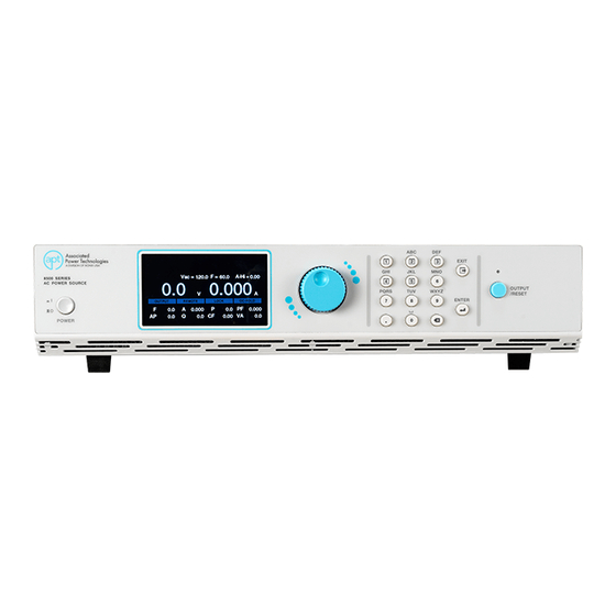
- Page 1 Via Acquanera, 29 22100 Como tel. 031.526.566 (r.a.) fax 031.507.984 info@calpower.it www.calpower.it 8500 Series Programmable AC Power Source Operation Manual for Models 8505, 8512, 8520, 8540 V1.00 Part # 40237...
- Page 2 Associated Power Technologies, a Division of Ikonix USA Address: 28105 N Keith Drive Lake Forest, IL 60045 Product Name: APT 8500 Series Power Source Model Number: 8505, 8512, 8520 & 8540 Conforms to the following Standards: Safety: EN 61010-1:2010 EMC:EN 61326-1:2013 Class A, IEC 61000-3-1 1:2000, IEC 61000-3-12:201 1, EN 61326-2-1:2013, IEC 61000-...
-
Page 3: Table Of Contents
Table of Contents This manual is an interactive PDF. Click each heading below to jump directly to the topic you need. Web addresses are also interactive. 1. Introduction 1.1 Warranty 1.2 Glossary 1.3 Safety Symbols 1.4 Safety Percaution 1.5 Service and Maintence 2. - Page 4 8 Options 8.1 Option 01 – Programmable 8.2 Option 03 – GPIB Interface 9. Calibration Procedure 80-87 9.1 Enter Calibration Screen 80-81 9.2 Calibration of Voltage Setting and Measurement (Low Range) 81-84 9.3 Calibration of Voltage Setting and Measurement (High Range) 9.4 Calibration of Current Measurement 85-86 9.5 View Calibration Data...
-
Page 5: Introduction
This warranty does not cover accessories not of Associated Power Technologies, a Division of Ikonix USA manufacture. Except as provided, herein APT makes no warranties to the purchaser of this instrument. All other warranties, expressed or implied (including, without limitation, merchantability or fitness for a particular purpose), are hereby excluded, disclaimed and waived. -
Page 6: Glossary
1.2 Glossary of Terms Alternating Current (AC) - Current that reverses direction on a regular basis (usually 60 times per second in the United States). Measured in amps. AC Power Source - An instrument that takes one AC voltage and frequency level and converts it into another AC voltage and frequency level. -
Page 7: Safety Symbols
Safety Agency Listing - A safety mark given to a product that has met stringent benchmarks as classified by the autho- rized agency. Steady State Current - A term used to describe the current when the load is running nominally after the inrush current. Switching Power Source - A power source that uses switching technology (integrated circuits and components) in order to generate the AC voltage, current, frequency, and power. -
Page 8: Safety Percaution
APT or its distributors. Service Interval The instrument must be returned at least once a year to an APT authorized service center for calibration and inspection of safety related components. APT will not be held liable for injuries suffered if the instrument is not properly maintained and safety checked annually. -
Page 9: Getting Started
2. Getting Started This section contains information for the unpacking, inspection, preparation for use, and storage of your APT product. 2.1 Unpacking and Inspection Your instrument was shipped in a protective shipping carton designed to protect the instrument through the shipping process. -
Page 10: Instrument Power Switch
Be sure to select the appropriate wire gauge for use with the APT 8500 AC power source. The line cord and all applicable fixturing must be capable of handling the output current produced by the AC power source. -
Page 11: Environmental Conditions
or H03 sheathed flexible cord according to IEC 60227, designation H03 VV-F VVH2-F (for equipment mass not exceeding 3 kg), or H05 VV-F or H05 VVH2-F2 (for equipment mass exceeding 3 kg), and be rated for at least 3G 0.75 mm² (for rated current up to 10 A) or 3G 1.0mm²... -
Page 12: Packaging
Failure to ship your instrument without an RMA number will result in additional fees for handling and storage. APT will not be responsible for any repair costs associated with shipping damage as a result of improper packaging. The customer is responsible for providing adequate shipping insurance coverage while shipping an instrument in the event of loss or damage while in transit. - Page 13 8505 8512 8520 8540 Models DC Output Power Rating 300W 750W 1200W 2400W 0 - 210V 3.0A 7.5A 12.0A 24.0A Max. Current (*2) 0 - 420V 1.5A 3.75A 6.0A 12.0A < 700mV < 800mV Ripple & Noise (rms) (*6) Range <...
- Page 14 8505 8512 8520 8540 Models Measurement 0.1 - 999.9s, 0 = OFF Range Ramp Up 0.1s Resolution (Programmable Option) ± (0.1% + 1 Cycle) at Output frequency ≤ 10Hz Accuracy ± (0.1% + 0.1 sec) at Output frequency > 10Hz 0.0~1200Hz Range 0.1Hz / 1Hz...
- Page 15 8505 8512 8520 8540 Models Measurement Range 0.0 - 20.0Apk 0.0 - 50.0Apk 0.0 - 80.0Apk 0.0 -160.0Apk Peak Current Resolution 0.1A Measurement Accuracy ± (0.5% of reading ± (0.5% of reading (Programmable Option) +8 counts) +12 counts) Reactive Power Range 0.0 - 75.0VAR 0.0 - 300.0VAR...
- Page 16 Standard: USB & LAN, Optional: GPIB Interface SCPI bus commands for full instrument control. (Programmable Option) Mimic Mode option for APT 6000, 7000 & 300XAC series power sources. Alarm Volume Setting Range: 0-9; 0=OFF, 1 is softest volume, 9 is loudest volume Graphic Display 4.3”...
- Page 17 8505 8512 8520 8540 Models System Parameters & Features Models ≥74% (at Full load) ≥81% (at Full load) ≥84% (at Full load) ≥84% (at Full load) Efficiency (*1 1) Count 0 - 50000, 0 = Continuous Power Up ON, OFF, LAST Test Results List mode only (Programmable Option)
- Page 18 8505 8512 8520 8540 Models Standard Accessories Interlock Disable Key (1505) USB Cable Shorting bar Input/Output Terminal Protection Box Power Cord (125Vac/10A) Rack Mount (2U) Rack Mount (4U) Handle for Rack (2U) Why use the term “Counts”? Associated Power Technologies publishes some specifications using COUNTS which allows us to provide a better indication of the tester’s capabilities across measurement ranges.
-
Page 19: Output Power, Power Factor And Output Current Considerations
3.2 Output Power, Power Factor and Output Current Considerations The reactive output power specification of APT 8500 series, models 8505, 8512, and 8520 change depending on the power factor of the load. While the 8505, 8512 and 8520 are specified as 400VA, 800VA and 1.6kVA units respectively, they can actually output up to 25% more reactive power based on the power factor of the load, thus keeping the real power under the specified limit. -
Page 20: Instrument Controls
Model 8520 Model 8540 3.3 Instrument Controls 3.3.1 Front Panel Controls (All models) 1. Power Switch - Power switch to power the source ON ( | ) and OFF (0). 2. Graphic Display - 480 x 272 TFT LCD. 3. Rotary Knob - Multifunctional rotary knob. 4. - Page 21 3.3.2 Rear Panel Controls Model 8505 Models 8512 and 8520 © Ikonix USA...
- Page 22 3.3.2 Rear Panel Controls Model 8540 1. Thermal Fans - Used to cool the instrument. Automatically controlled. 2. Signal Input/Output Connectors a. Signal Input: 9-Pin D-type subminiature male connector for remote control of OUTPUT ON, OUTPUT OFF/RESET, Output Verify, File Recall, Trigger, and REMOTE INTERLOCK DISABLE functions. b.
- Page 23 3.3.3 Functional Keys The multi-functional keys on the front panel keypad enable you to navigate through the instrument, change the meter display, name files, and change parameters. Below is a list of all multi-functional keys. Soft Keys Description All keys Press any key on the keypad (except for the OUTPUT/RESET key) to drop down the main menu.
-
Page 24: Programming Instructions
Programming Instructions 4.1 Powering on the Instrument Turn on the Power switch located on the lower left-hand corner of the front panel. The initialization screen will appear. After a few seconds the initialization screen will change to the test screen. The test screen will be displayed as follows: *Note –... -
Page 25: System
If you press any key on the keypad within the test screen a drop-down menu will appear on the top of the screen displayed as follows: The drop-down menu will display Mode, File, Meter, and System. The output mode and test file name will also be displayed on this screen (marked in the red box) on the image above. - Page 26 Lock ON/OFF state press and hold the Exit key on the keypad until your hear a beep. Allows you to set the APT 8500 Series source in compatibility mode to mimic the bus 300XAC/6000/7000/ Mode command structure of APT models 300XAC, 6000 and 7000.
-
Page 27: Editing System Parameters
System Parameter Setting/ Description Range Allows you to restore default factory settings (requires a password). This function is for troubleshooting purposes. Contact us for more information. Factory Default Performing Factory Default will delete all test files and restore all system settings. Allows you to select a maximum voltage threshold, or ceiling level, for the AC output Calibration voltage programmed in the test parameters. -
Page 28: Mode And File
5. Rotate the knob or use the keypad to change 6. Press the rotary knob or the ENTER key on the the parameter to the desired value: keypad to save the value. The parameter will be saved and the next parameter will be highlighted. 7. - Page 29 4.4.1 Create Test File – Manual Mode 1. From the Mode menu press the number 2. Once the Mode has been set to Manual press 1 key on the keypad to change the Mode to any key to drop down the menu bar then press Manual.
- Page 30 7. The next screen will display a field with a 8. Use the keypad to enter a name for the test blinking cursor to enter a name for the file: file (23 character limit): 9. After entering the file name press the ENTER 10.
- Page 31 4.4.2 Manual Mode - Test Parameters The Manual Mode allows you to program an AC, DC or AC+DC (coupled) output. Along with the standard Sine wave, you can also choose from Triangle, Square and Clipped output waveform. Detailed descriptions of all the available test parameters in Manual Mode are listed in the following table Manual Mode - Test Parameters Parameter Setting/Range...
- Page 32 Manual Mode - Test Parameters Parameter Setting/Range Description Sets the power source for a square output waveform: SQUARE (0 - 219V, 0 - 310 V) WAVE Sets the power source for a clipped-sine waveform: CSIN (0 - 155V, 0 - 310V) Sets the power source in an Auto Range mode.
- Page 33 4.4.3 Create Test File – List Mode 1. From the Mode menu press the number 2 2. Once the mode has been set to List press any key on the keypad to change the mode to List. key to drop down the menu bar and press the The next screen displayed will reflect the mode number 2 key on the keypad to enter the File as List, along with a test file name or a “No File...
- Page 34 7. After entering the file name press the ENTER 8. Use the rotary knob to highlight Program key on the keypad to save the file name and Setup or the first sequence parameters. To edit display the Program Setup along with the first the parameters you can do one of the following: sequence.
- Page 35 The Program Setup and sequence parameters can be edited in the exact same manner as described in the previous sections, using a combination of rotary knob and keypad. 2. When choosing to copy a sequence the 1. To Add a new sequence press the number 1 message on the screen below will be displayed.
- Page 36 The previous waveform was generated using the following parameters of the List Mode sequences: SEQ 1 SEQ 2 SEQ 3 Wave Wave Wave Sine Sine Sine Start Angle Start Angle Start Angle Time unit Time unit Time unit Time Time Time Detailed descriptions of all the available test parameters in the List Mode are listed in the following table: List Mode - Sequence Parameters...
- Page 37 List Mode - Additional Metering Parameter Setting/Range Description See Specifications Provides the flexibility to program a maximum current threshold or ceiling A-Hi in section 3.1 level. When this level is reached a failure will occur. Provides the flexibility to program a minimum current threshold or floor See Specifications level.
- Page 38 List Mode - Program Setup List Mode Program Setup parameters only apply when Trigger is set to Manual. These parameters determine what happens before you trigger the first sequence of the List Mode output. If the Trigger is set to Auto and you start the test these parameters will not matter since the first sequence starts right away.
- Page 39 4.4.5 Create Test File – Step Mode 1. From the Mode menu press the number 3 2. Once the Mode has been set to Step press key on the keypad to change the Mode to Step. any key to drop down the menu bar and press The next screen displayed will reflect the Mode the number 2 key on the keypad to enter the as Step, along with a test file name or a “No File...
- Page 40 7. After entering the file name press the ENTER 8. The test parameters can be edited in the key on the keypad to save the file name and exact same manner as the system parameters, display the test parameters for editing: using a combination of the rotary knob and keypad.
- Page 41 Detailed descriptions of all the available test parameters in Step Mode are indexed in the following table: Step Mode - Test Parameters Parameter Setting/Range Description Count 0 – 50000 0=Off Sets the number of counts. Trigger Auto/Manual Sets the trigger to auto or manual for triggering the counts. Base Time/Cycle Sets the base to time or cycle.
- Page 42 4.4.7 Create Test File – Pulse Mode 1. From the Mode menu press the number 2. Once the Mode has been set to Pulse, press 4 key on the keypad to change the Mode to any key to drop down the menu bar and press Pulse.
- Page 43 7. After entering the file name, press the ENTER 8. The test parameters can be edited in the key on the keypad to save the file name and exact same manner as the system parameters display the test parameters for editing: using a combination of the rotary knob and keypad.
- Page 44 Detailed descriptions of all the available test parameters in the Pulse Mode are listed in the following table: Step Mode - Test Parameters Parameter Setting/Range Description Count 0 – 50000 0=Off Sets the number of counts. Trigger Auto/Manual Sets the trigger to auto or manual for triggering the counts. Sets the power source in an Auto Range mode.
-
Page 45: Edit, Copy, Delete, And Load Test File
4.5 Edit, Copy, Delete, and Load Test File After creating test files the user has the option to edit, delete, copy, or load the test file to start testing. 4.5.1 Edit 1. To edit an existing test file the user must 2. - Page 46 4.5.2 Copy 2. The selections in the menu bar will change and 1. When the File menu appears press the number the option to select Copy, Delete, or Next will 4 key on the keypad to view the Next page: appear: 4.
- Page 47 4.5.3 Delete 1. To Delete a test file select the Mode and go to 2. Use the rotary knob to select the file to be the File menu to view the list of test files. Press deleted. The Delete selection will appear on the the number 4 key on the keypad to view the next menu bar, press the number 2 key on the keypad page:...
-
Page 48: Perform Test
5. Perform Test Once a test file is loaded, the power source is ready to start outputting. Make all of the necessary test connections to the DUT (Device Under Test) and perform all safety measures before performing the test. Pressing the OUTPUT/ RESET key will start a test. -
Page 49: List Mode
5.3 List Mode 1. The List Mode test screen will appear similar to 2. The user can press the OUTPUT/RESET key at the following: any time during the test to end/abort the test. 5.4 Step Mode 1. The Step Mode test screen will appear similar to 2. -
Page 50: Results
5.6 Results 1. The test results are available for viewing in List 2. The Results screen will appear and the rotary Mode only. Users can view the test results once knob can be used to view the results: the test has ended by pressing any key on the keypad to drop down the menu bar and pressing the number 4 key on the keypad: *Note –... -
Page 51: Perform Test Screen Considerations
5.7 Perform Test Screen Considerations The Perform Test screen displays a few select System Parameters if they were enabled by the user prior to performing a test. If the power source is controlled using a PC an icon appears on the screen to indicate PC control. -
Page 52: Error And Failure Messages
5.8 Error and Failure Messages The APT 8500 Series power sources can display several error or failure messages during an abnormal condition. When an abnormal condition occurs, the output will disable and the alarm will sound. The OUTPUT/RESET LED indicator will also begin flashing. See sections 3.1 Specifications and 4.2 System for details on the available ranges for all test and system parameters. - Page 53 Process to Clear Press EXIT key Wait 5sec, Reboot. If error Contact Code Description Press EXIT key message repeats Manufacturer contact manufacturer • Displayed when the output voltage measurement is greater than the output voltage setting by 5V in the VSENSE_INT_OVP Lo range and 10V in the Hi range.
- Page 54 Process to Clear Press EXIT key Wait 5sec, Reboot. If error Contact Code Description Press EXIT key message repeats Manufacturer contact manufacturer • Displayed when the voltage value for AC+DC coupling SET_FAIL is greater than the voltage range: Hi – 438V, Lo – 219V •...
- Page 55 Process to Clear Press EXIT key Wait 5sec, Reboot. If error Contact Code Description Press EXIT key message repeats Manufacturer contact manufacturer • • Displayed when the maximum current during the power factor correction is as follows: PFC_OCP Model 8505 > 10Arms Model 8512 >...
- Page 56 Process to Clear Press EXIT key Wait 5sec, Reboot. If error Contact Code Description Press EXIT key message repeats Manufacturer contact manufacturer • Displayed when the reactive Q-Hi power value exceeds the Q-Hi setting. • Displayed when the reactive Q-Lo power value stays below the Q-Lo setting.
-
Page 57: Remote Plc
Signal Output The rear panel Signal Output connector of the APT 8500 Series provides output signals to remotely monitor PASS, FAIL, and PROCESSING conditions via a 9-Pin D-type connector. When a terminal becomes active the relay closes thereby allowing the external voltage to operate an external device. These are normally open free contacts and will not provide any voltage or current. - Page 58 Signal Input The rear panel Signal Input connector of the APT 8500 Series can be used to control any test operation via remote. The 9-Pin D-Type connector enables remote operation for OUTPUT, RESET, Remote Interlock, File Recall and Trigger functions. Remote functions will be activated once the PLC Remote parameter from the System menu is turned on.
- Page 59 Memory Input Control Selection of up to 7 test file locations is achieved by using a Normally Open (N.O) Momentary Button. The truth table below provides the pin locations needed in order to select the memories. File Location PIN 1 PIN 9 PIN 8 ©...
-
Page 60: Bus Remote Interface Usb/Lan/Gpib (Programmable Option Only)
This section provides information on the proper use and configuration of bus remote interface. The USB and LAN interfaces are standard on 8500 series models, an optional GPIB (IEEE-488) interface is also available. Please refer to Section 10 Options of this manual for details on the 8500 series options. -
Page 61: Lan Configuration
LAN Configuration Default Settings The default settings for the Ethernet interface are as follows: IP Setup: AUTO IP Address: 010.000.000.000 Mask Addr: 255.000.000.000 Gateway Addr: 000.000.000.000 The communication port for the TCP on LAN connections is 10001. Manual setup of LAN configurations is also available. The LAN Config parameter can be accessed from the second page of the System menu: 7.3 SCPI (Standard Commands for Programable Instruments) Basics This section describes how SCPI information is organized and presented in this manual. - Page 62 Special Characters in Command Character Meaning Example OUTPut:MODE MANual|LIST|PULSe|STEP A vertical bar between keywords indicates alternative choices between parameters. MANual, LIST, PULe or STEP are the choices OUTPut:CURRent[:LIMit]:HIGH <numeric_value> Square brackets indicate an optional keyword. These implied keywords will LIMIt is an optional item. execute even if they are omitted.
-
Page 63: Scpi Command Tree
SCPI Command TREE Program Commands and Companion Queries These commands are used to modify individual test parameters within each file and/or sequence. Many of these commands require a parameter value to be included with the command. The companion query command will read the parameter. The writing of the parameter requires that the unit not be included with the value and only the numeric value should be included with the command. - Page 64 7.4.2 Measure Subsystem BASE KEYWORD DESCRIPTION VALUE Voltage, Vac voltage, Vdc voltage, Current, AC current, MEASure :ALL? Query Meter Data DC current, Frequency, Power, Pfactor, APEAK, Reactive, Crestfactor, Apparent OFF, ON, TRIG TO TEST, Ramp Up , Ramp Down , OVP_PEAK , OCP_PEAK , OPP_PEAK , OVP , OCP , OPP , FAN_FAIL , DA_OTP , MCU_FAIL ,...
- Page 65 7.4.3 Mode and File Subsystem A) Manual Mode Commands and Companion Queries These commands are used to modify test parameters for the Manual mode on the instrument. The operating mode of the unit should be put in Manual mode for the commands below to work successfully. These commands require a parameter value to be included with the command.
- Page 66 © Ikonix USA...
- Page 67 BASE KEYWORD DESCRIPTION VALUE LIST :SEQuence:COPY <value> Copy Sequence :SEQuence:DELete <value> Delete Sequence :SEQuence:TOTal? Query Sequence Total :SEQuence:WAVE SINE, TRIangle, SQUare, Set Output Waveform :SEQuence:WAVE? CLIPped :SEQuence:THD <value> Set THD Value *Clipped wave only :SEQuence:THD? :SEQuence:ANGLe[:STARt] Set Start Angle 0 – 359° :SEQuence:ANGLe[:STARt]? :SEQuence:VOLTage:AC:STARt <value>...
- Page 68 BASE KEYWORD DESCRIPTION VALUE :SEQuence:CREStfactor[:LIMit]:HIGH Set Crest Factor High Limit 0.00 – 10.00, 0 = OFF :SEQuence:CREStfactor[:LIMit]:HIGH? :SEQuence:CREStfactor[:LIMit]:LOW Set Crest Factor Low Limit 0.00 – 10.00, 0 = OFF :SEQuence:CREStfactor[:LIMit]:LOW? :SEQuence:APParent[:LIMit]:HIGH Set Apparent Power High 0 – 1250 VA, 0 = OFF* :SEQuence:APParent[:LIMit]:HIGH? Limit See Specs...
- Page 69 BASE KEYWORD DESCRIPTION VALUE :SEQuence:ANGLe[:STARt] Set Start Angle 0 – 359° :SEQuence:ANGLe[:STARt]? :VOLTage:AC <value> Set Output AC Voltage 0.0 – 310.0 VAC :VOLTage:AC? VOLTage:DC <value> Set Output DC Voltage 0.0 – 420.0 VDC :VOLTage:DC? :FREQuency Set Frequency 5 – 1200 Hz :FREQuency? :TIME[:DWELl] <value>...
- Page 70 BASE KEYWORD DESCRIPTION VALUE :FILE:TOTal? Query File Total :FILE:INDex <value> Edit or Open File :FILE:INDex? :FILE:INDex? Set File Index :FILE:NAME? Query File Name :COUNt Count 0 – 50000, 0 = OFF :COUNt? :TRIGger <value> Set Trigger Mode AUTo, MANual :TRIGger? :RANGe <value>...
- Page 71 7.4.5 Result Subsystem Result Queries These commands are used to query results data from the instrument. The query command will read the parameter that is stored for each Sequence in the List Mode operation. For other output modes, use MEASURE Subsystem commands to query live data while the unit is outputting. BASE KEYWORD DESCRIPTION...
- Page 72 BASE KEYWORD DESCRIPTION VALUE :CREStfactor? Query Crest Factor 0.0 – 10.00 :APParent? Query Apparent Power *See Specifications 7.4.6 System Subsystem System Commands and Companion Queries These commands are used to modify the system parameters for the instrument. The parameters below control the global system parameter that applies in all Output Modes of this power supply.
- Page 73 Execution Time Restrictions The following commands require a higher amount of processing time which may be higher than the rest of the commands list. Allow the listed “Execute Time” as the minimum time in order to successfully execute the command. COMMAND TIMING LIST Command Execute Time...
-
Page 74: Gpib Interface
Each device on the GPIB (IEEE-488) interface must have a unique address. You can set the address of the 8500 series to any value between 0 and 30. The address can only be set from the front panel. The address is stored in non-volatile memory and does not change when the power has been turned off or after a remote reset. - Page 75 Interface Functions The capability of a device connected to the bus is specified by its interface functions. These functions provide the means for a device to receive, process, and send messages over the bus. The interface functions are listed in the chart below: Interface Function Subset Description...
-
Page 76: Gpib/Usb/Lan Interface Sample Command List
A GPIB read command must be sent after the command strings, to retrieve any data from a query command (?). The APT 8500 series GPIB bus will not send any data to the controller without being queried. The USB/LAN bus will automatically send any response back to the controller’s input buffer. Each command string should be terminated with the ASCII control code, New Line <NL>, OAh or the end of line... - Page 77 MEASure:ALL? Reads the active data being displayed on the LCD display while the test is in process. This command will also read the last data taken when the test sequence has completed. Each parameter is separated by commas and includes frequency value, voltage value, current value, power value, peak current value, power factor value and timer metering.
- Page 78 METer? Reads the selected meter value. Returns meter name. <Current>,<Adccurrent>,<Frequency>,<Power>,<Pfactor>,<APEAK>,<Reactive>,<Crestfactor>, <Apparent> Each meter will contain only the value and not the units. 7.6.2 IEEE 488.2 Common Commands System Commands and Companion Queries These commands are required by the IEEE-488.2 standard with the exception of *PSC, *PSC?. Most of these commands are not available over the USB/RS-232 bus except for the *IDN? command which can be used to retrieve the instrument identification information, and the four status reporting commands *ESR?, *ESE, *ESE? and *STB?.
- Page 79 Power-On Status Query returns value = 0 or 1 *IDN? Reads the instrument identification string. Company = APT. *RST Resets the instrument to original power on configuration. Does not clear Enable register for Standard Summary Status or Standard Event Registers. Does not clear the output queue. Does not clear the power- on-status-clear flag.
- Page 80 *TST? Performs a self test of the instrument data memory. Returns 0 if it is successful or 1 if the test fails. *CLS Clears the Status Byte summary register and event registers. Does not clear the Enable registers. *OPC Sets the operation complete bit (bit 0) in the Standard Event register after a command is completed successfully.
- Page 81 7.6.3 Status Subsystem Operation and Questionable Status Registers STATus:OPERation[:EVENt]? Command Format STATus:CONDition? STATus:OPERation:ENABle <numeric_value> Description Operation Status Registers Enable and Query Example STATus:CONDition? STATus:OPERation[:EVENt]? Command Format STATus:CONDition? STATus:OPERation:ENABle <numeric_value> Description Operation Status Registers Enable and Query Example STATus:CONDition? Item Name Value STAT:OPER:COND? Operation Status Register Query...
- Page 82 7.6.3 Status Subsystem © Ikonix USA...
-
Page 83: Options
8. Options This section contains a list and descriptions of available factory installed options. The list of options contains an option code number along with a description of the option: Option Code Option Name Programmable GPIB Interface 8.1 Option 01 – Programmable This option provides programmable capability to the instrument. -
Page 84: Calibration Procedure
9. Calibration Procedure All Associated Power Technologies (APT) instruments have been calibrated at the manufacturing factory prior to delivery. The recommended calibration cycle for all APT instruments is every 12 months. The following meters and accessories will be required to calibrate this instrument: •... -
Page 85: Calibration Of Voltage Setting And Measurement (Low Range)
9.2 Calibration of Voltage Setting and Measurement (Low Range) Connect Meter Connect the outputs of APT 85XX to DVM. DVM is adjusted to Vdc measurement. From the calibration main screen use the rotary Use the rotary knob to highlight 155V Offset knob to highlight Voltage Setting &... - Page 86 Connect 210VDC voltage meter. Observe the voltage measurement on the DVM, then input the “negation value” of the measurement (e.g. DVM Vdc= 1234mV, input the value “-1234” , press the . key to enter the +/- symbol). Do NOT press the ENTER key after inputting the value.
- Page 87 Input the Vdc measurement of the DVM. This calibration item has been completed Press the 1 key to save the correction value Press the ENTER key to enter the next page. Adjust Meter DVM is adjusted to Vrms measurement. Use the rotary knob to highlight 155V AC Voltage Connect 155VAC voltage meter.
-
Page 88: Calibration Of Voltage Setting And Measurement (High Range)
Input the DVM measured Vrms value. This calibration item has been completed Press the 1 key to save the correction value. (This item is 1000 Hz AC measurement correction) 9.3 Calibration of Voltage Setting and Measurement (High Range) From the calibration main screen use the rotary knob to highlight the Voltage Setting &... -
Page 89: Calibration Of Current Measurement
Calibration of Current Measurement From the Calibration main screen use the Rotary Use the Rotary knob to highlight the Current knob to highlight the Current Measurement Offset selection. Press the ENTER key to enter the selection. Press the ENTER key to enter the next next page. - Page 90 Confirm that there is a connection to the load. Press the 1 key to confirm. Reference the selection. Press the ENTER key to view the next page. following table for proper resistive load values for each of the four different APT 8500 models: Model Amp Meter Load 8505 10Ω...
-
Page 91: View Calibration Data
9.5 View Calibration Data After the calibration is completed successfully the user can view the calibration data. Access the calibration selection from the Use the rotary knob to view page 1 of calibration System menu and enter password 8080 to view data. -
Page 92: Service And Maintence
10. Service and Maintenance User Protection To avoid electrical shock do not dismantle the cover of the instrument. When any abnormal symptom happens with the instrument, please contact Associated Power Technologies or the authorized distributor for assistance. Consistency of Service The instrument’s internal circuits and all related parts are required to be checked and calibrated at least once every year. -
Page 93: Replacement Parts List
11. Replacement Parts List Part Number Quantity Ref Designator Description Supplied Accessories 33189 8505 Input Power Cable 39534 Romex cable strain relief 1" 40291 Romex cable strain relief 1/2" 40257 Interlock Key 40280 2U Rack Mount Handle 40281 2U Rack Mount Bracket 40290 Protective Junction Box for Output Terminals (2U) 40338... - Page 94 Part Number Quantity Ref Designator Description PCB Assemblies 40238 AMP8020 Main Amplifier Board Assembly PCB (8505) 40239 DDC8020 DC to DC Converter Board Assembly PCB (8505) 40245 AMP8020 Main Amplifier Board Assembly PCB (8512) 40248 DDC8020 DC to DC Converter Board Assembly PCB (8512) 40247 AMP8020 Main Amplifier Board Assembly PCB (8520)
Need help?
Do you have a question about the 8500 Series and is the answer not in the manual?
Questions and answers