Cleveland Convotherm Combination Oven-Steamer Gas 20.20 Service And Parts Manual
Combination oven-steamer
Hide thumbs
Also See for Convotherm Combination Oven-Steamer Gas 20.20:
- Specification sheet (2 pages) ,
- Buyer's manual (7 pages)
Table of Contents

Related Manuals for Cleveland Convotherm Combination Oven-Steamer Gas 20.20


Summary of Contents for Cleveland Convotherm Combination Oven-Steamer Gas 20.20
- Page 1 Service & Parts Manual Convotherm Combination Oven-Steamer MODELS: Gas 20.20 OGS-20.20 OGB-20.20 1333 East 179th St., Cleveland, Ohio, U.S.A. 44110 Phone: (216) 481-4900 Fax: (216) 481-3782 Enodis Visit our web site at www.clevelandrange.com 0706...
-
Page 2: Table Of Contents
Installation Operating Instructions Cleaning Instructions Service Parts Maintenance For the Installer ..........1 Warranty . -
Page 3: For Your Safety
Failure to disconnect power can result in death, injury, and property damage. ALL SERVICE MUST BE PERFORMED BY A QUALIFIED CLEVELAND RANGE AUTHORIZED TECHNICIAN. Do not connect the Combi Oven-Steamer drain connection to any drain material that cannot sustain 140 Using drain material that cannot withstand 140 result in injury, equipment damage, and property damage. -
Page 4: Warranty
CLEVELAND RANGE agrees to repair or replace, at its option, f.o.b. factory, any part which proves to be defective due to defects in material or workmanship during the warranty period, providing the equipment has been unaltered, and has been PROPERLY INSTALLED, MAINTAINED, AND OPERATED IN ACCORDANCE WITH THE CLEVELAND RANGE OWNER’S MANUAL. -
Page 5: General Information
GENERAL INFORMATION ABOUT COMBIS A. PRODUCT INFORMATION Cleveland Range, LLC assigns two product identification numbers to each Combi: a model number and a serial number. The model number identifies the product characteristics. The serial number identifies the individual Combi. 1. Model Number a. -
Page 6: Installation Instructions
Combi can result in DEATH, INJURY, EQUIPMENT DAMAGE, and void the warranty. NEVER install damaged Combis. ALWAYS have qualified Cleveland Range authorized personnel install and service Combis. 5. Inspect the Combi for shipping damage. a. Check carton and packing for shipping damage. - Page 7 3. Position and level the Combi. 4. Connect the utility lines after positioning and leveling the Combi. 5. Call Cleveland Range at 216-481-4900 for the Free Start-Up Program’s Performance Checkout. 6. After Setup and Performance Checkout, the Combi should provide years of reliable operation.
-
Page 8: Instructions For Casters
5. Follow the separate instructions included with the Stand, Stacking Kit, or Caster Kit. 6. Make sure the Stand, Stacking Kit, or Caster Kit matches the Combi(s). 7. Use only genuine Cleveland Range Stands, Stacking Kits, Caster Kits, and replacement parts. -
Page 9: Ogb-20.20
ITEM NUMBER __________________________________________ JOB NAME / NUMBER __________________________________ Short Form Specifications Shall be Cleveland Model: OGB-20.20 Combination Convection Oven / Steamer with simple to operate electronic programmable controls for Hot Air, Convection Steam, and Combination cooking modes, "Cook & Hold" and "Delta T"... -
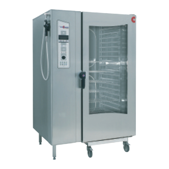
Page 10: Front View
Cleveland Range reserves right of design improvement or modification, as warranted. Many regional, state and local codes exist and it is the responsibility of the owner and installer to comply with the codes. Cleveland Range equipment is built to comply with applicable standards for manufacturers. 2.80"... -
Page 11: Ogs-20.20
ITEM NUMBER __________________________________________ JOB NAME / NUMBER __________________________________ Short Form Specifications Shall be Cleveland Model: OGS-20.20 Combination Convection Oven / Steamer with simple to operate electronic programmable controls for Hot Air, Convection Steam, and Combination cooking modes, "Cook & Hold" and "Delta T"... - Page 12 Cleveland Range reserves right of design improvement or modification, as warranted. Many regional, state and local codes exist and it is the responsibility of the owner and installer to comply with the codes. Cleveland Range equipment is built to comply with applicable standards for manufacturers. 2.80"...
-
Page 13: Control Panel Basic Operation
CONTROL PANEL BASIC OPERATION A. QUICK START GUIDE ALWAYS PRE-HEAT THE OVEN CHAMBER! 1. Switch on with key (1). 2. Select cooking mode with keys (2-5). 3. Press key (6) to start. 1. Press key (18) and rotate Selector Dial (23) to set oven temperature. -
Page 14: Control Panel Detail View
B. CONTROL PANEL DETAIL VIEW Note: Item numbers correspond to numbers on the control panels in Figure 4-1b 1. ON/OFF When the Combi is turned ON: • Self-diagnosis is performed. • Oven light turns on. • Steam generator fills and heats (OEB and OGB models). - Page 15 Function Indicators • Light up when function or activity is engaged: 10. Reduced Power 11. Burner or Electric Heating ON 12. Reduced Fan Speed 13. Cooking Mode Engaged 14. Button Lock 15. Crisp & Tasty Engaged 16. Program Protection 17. Display •...
-
Page 16: At The End Of The Day Or Shift
Combi oven chamber. h. Do NOT spray water into a hot oven chamber. Use only genuine Convotherm by Cleveland and Cleveland Range cleaning and descaling products. Follow the instructions and heed and obey the warnings on the labels. Other products can cause injury, present heath hazards, and damage the Combi. - Page 17 If U-Shaped racks become bent then remove the Combi from service and contact your qualified Cleveland Range authorized service representative at once. c. Clean the interior of the of the double glass doors daily.
- Page 18 To remove this deposit, use vinegar and a soft cloth. • Ask your qualified Cleveland Range authorized service representative about adding or setting a water treatment system. Drain Cover and Drain...
-
Page 19: Semi- Automatic Cleaning Of Oven Chamber
B. Semi-Automatic Cleaning of the Oven Chamber NOTE: Do NOT press the Start/Stop key while using the Semi-automatic Cleaning process. This stops the cleaning process. The Semi-Automatic Cleaning process is designed to be started when the oven chamber temperature is at or below 158°F. Death, injury, and equipment damage can result from starting the Semi-Automatic Cleaning process when the oven chamber is above 158°F. - Page 20 a. The third step is Steam mode at 86°F for 1 minute. No action is needed. b. The fourth step is Steam at 212°F for 10 minutes, followed by a Signal Tone. 15. Turn OFF the Combi when the Signal Tone sounds. 16.
-
Page 21: Convoclean Automatic Cleaning System (Optional)
C. CONVOClean Automatic Cleaning System (optional): NOTES: • Do NOT interrupt the automatic cleaning process. Interrupting and restarting the Automatic Cleaning System with the ON/OFF key may start a 6 minute forced rinsing of the oven chamber to remove any CONVOClean and CONVOCare residue when the ON/OFF key is turned back ON. - Page 22 “Strong Soiling” ‘Strong Soiling – Shining+” 8. Press the Smart Key. 9. “Food inside oven?” appears in the display. 10. If the oven is empty, then answer “No.” 11. Confirm by pressing the Smart Key. 12. “Start auto-cleaning?” appears in the display. 13.
-
Page 23: Descale Steam Generator
Spent material is considered non- hazardous and may be disposed of in a sewer system with water flush. The liquid solution in Cleveland Range Descaler Solution Part No. 106174, “ can be harmful if not handled properly. - Page 24 Do NOT heat the Combi during descaling. Death, injury, equipment and property damage can result. This procedure is slightly different depending on the model being descaled. This entire procedure should be read and fully understand as it applies to the model being descaled, before beginning the actual descaling operation.
- Page 25 • While adding liquid to the steam generator through the descaler inlets, pour slowly to avoid overflow. • Wipe up any spills at once to avoid etching. 6. After the automatic fill cycle has ended, turn OFF the Combi with the ON/OFF key, and at the Control Power Service Disconnect switch located below the hand shower.
- Page 26 2020 GAS GENERATOR W CLEANING Washer Arm C2611068 Spray Handle Shut Off Valve C6014003 Light Gasket C6015020 Lamp C5005043 Condensate Box o-ring C6015000 Spray Handle Bracket C2002042 C3216313 B 0706...
- Page 27 2020 GAS GENERATOR W CLEANING I I T T E E M M Q Q T T Y Y P P A A R R T T N N 0 0 . . D D E E S S C C R R I I P P T T I I O O N N C2114828 ASSEMBLY/WELDMENT, TOP, INTERMEDIATE, 12.20/20.20 C2115487...
- Page 28 2020 GAS INJ W CLEANING Washer Arm C2611068 light Gasket C6015020 Lamp C5005043 Condensate Box o-ring C6015000 Spray Handle Bracket C2002042 Spray Handle Shut Off Valve C6014003 C3216313 B 0706...
- Page 29 2020 GAS INJ W CLEANING I I T T E E M M Q Q T T Y Y P P A A R R T T N N 0 0 . . D D E E S S C C R R I I P P T T I I O O N N C2114828 ASSEMBLY/WELDMENT, TOP, INTERMEDIATE, 12.20/20.20 C2115487...
- Page 30 COMPONENT PANEL ASSEMBLY, GAS OGB 20.20 MODELS 300504 A 0706...
- Page 31 COMPONENT PANEL ASSEMBLY, GAS OGB 20.20 MODELS I I T T E E M M Q Q T T Y Y P P A A R R T T N N 0 0 . . D D E E S S C C R R I I P P T T I I O O N N C5115405 PLATE, ELECTRICAL MOUNTING 20.20 C4014012...
- Page 32 ASSEMBLY, CONTROL PANEL, WITH PICTO ALL MODELS I I T T E E M M Q Q T T Y Y P P A A R R T T N N 0 0 . . D D E E S S C C R R I I P P T T I I O O N N C2114297 WELDMENT, CONTROL PANEL C5019101...
- Page 33 ASSEMBLY, OUTER BASE OGB 20.20 MODELS Pressure Switch C5009055 Agent Pump 300352 I I T T E E M M Q Q T T Y Y P P A A R R T T N N 0 0 . . D D E E S S C C R R I I P P T T I I O O N N 100413 FOOT ASS'Y, ADJUSTABLE (FOR 1.250 SQ.
-
Page 35: All Models
ASSEMBLY, WATER HOSE SYSTEM, CONDENSER ALL MODELS I I T T E E M M Q Q T T Y Y P P A A R R T T N N 0 0 . . D D E E S S C C R R I I P P T T I I O O N N C6015215 ELBOW, HOSE CONNECTION, 3/8"... - Page 36 ASSEMBLY, WATER VALVE ALL 20.20 MODELS I I T T E E M M Q Q T T Y Y P P A A R R T T N N 0 0 . . D D E E S S C C R R I I P P T T I I O O N N 300453 VALVE ASSEMBLY, 3WAY 240VAC 300363...
- Page 37 ASSEMBLY, WATER VALVE OGB 20.20 MODELS I I T T E E M M Q Q T T Y Y P P A A R R T T N N 0 0 . . D D E E S S C C R R I I P P T T I I O O N N 300456 VALVE ASSY.
- Page 38 ASSEMBLY, WATER VALVE OGS 20.20 MODELS I I T T E E M M Q Q T T Y Y P P A A R R T T N N 0 0 . . D D E E S S C C R R I I P P T T I I O O N N C6015401 BARB, 1/2 R X 3/8 HOSE C5001085...
-
Page 39: Burner Insert, Hl, Pre-Mounted All Gas Models
BURNER INSERT, HL, PRE-MOUNTED ALL GAS MODELS I I T T E E M M Q Q T T Y Y P P A A R R T T N N 0 0 . . D D E E S S C C R R I I P P T T I I O O N N C2010050 BURNER INSERT HL, 6.10/6.20, WELDMENT C2010052... - Page 42 ASSEMBLY, BURNER INSERT, AIR, LP & NAT GAS ALL GAS MODELS I I T T E E M M Q Q T T Y Y P P A A R R T T N N 0 0 . . D D E E S S C C R R I I P P T T I I O O N N C2616521 BURNER INSERT, HL, PRE-MOUNTED, 6.10/6.20 C2616522...
-
Page 45: Pump, Steam Generator, Gas, 110V All Gas Models
PUMP, STEAM GENERATOR, GAS, 110V ALL GAS MODELS I I T T E E M M Q Q T T Y Y P P A A R R T T N N 0 0 . . D D E E S S C C R R I I P P T T I I O O N N C6015101 C6015100 DRAIN ELBOW FOR STEAM GENERATOR... -
Page 46: Door (20.20 Models)
DOOR COMPLETE 20.20 MODELS Complete Door C2514356 Cross Gasket C7001077 I I T T E E M M Q Q T T Y Y P P A A R R T T N N 0 0 . . D D E E S S C C R R I I P P T T I I O O N N C2514363 ASSEMBLY, OUTER DOOR, 20.20 C2514394... - Page 47 SLIDING PLATE, COMPLETE ALL 6.20, 10.10 MODELS & 20.20 MODELS Siding Plate 20.20 C2614804 I I T T E E M M Q Q T T Y Y P P A A R R T T N N 0 0 . . D D E E S S C C R R I I P P T T I I O O N N C2614806 CARRIAGE PLATE, WELDED, 6.20...
- Page 48 SLIDING PLATE, COMPLETE ALL 6.20, 10.10 MODELS & 20.20 MODELS DETAIL B DETAIL C SECTION E-E DETAIL A 14 21 Page 2 of 2 19 20 SECTION D-D C2614801 B, C2614802 B & C2614804 P1 13 21 11 21 0706...
- Page 49 EXTERIOR SHEETING ALL 20.20 MODELS I I T T E E M M Q Q T T Y Y P P A A R R T T N N 0 0 . . D D E E S S C C R R I I P P T T I I O O N N C2514356 DOOR, 20.20, COMPLETE C2114657...
-
Page 50: Sequence Of Operations
CLEVELAND RANGE OGB 20.20 SEQUENCE OF OPERATIONS When using these instructions refer to the OGB 6.20 wiring schematic. 1 When 120 VAC is applied to the combi, it is sent to the Power Control Switch (S1). 2 When the Power Control Switch (S1) is closed The red light in the switch is energized. - Page 51 • If the condensate box is heated to 140 degrees F at the B3probe, 120 VAC is sent from terminal 5 of connector X12 to the condenser valve (Y1) until the temperature drops. b The display will show the set temperature and set time when the flush is done or a negative reply is made to the “Generator Flush?”.
- Page 52 (b) 24 VAC is sent from terminal 2 of connector X2 on the Steam Burner Control Module (N21) to the hot surface igniter (R20). (c) The gas valve is energized allowing gas and air into the burner chamber to be ignited by the hot surface igniter. (d) The Steam Burner Control Module (N21) senses between 0.5 and 4.0 micro-amps DC from the flame sensor (P1) at terminal 3 of connector X2 (within 4 seconds) and sends a signal from terminal 2 of connector...
- Page 53 • A request for heat is sent from terminal 3 of connector X21 on the Gas Board (A20) to terminal 10 on connector X1 on the Steam Burner Control Module (N21) ◊ 24 VAC is sent from terminal 2 of connector X2 on the Steam Burner Control Module (N21) to the hot surface igniter (R20).
- Page 54 ◊ Every 120 seconds the rotation of the motor reverses. ◊ NOTE: If the temperature is less than 212 degrees F than fan will be pulsed on for 2 seconds every 60 seconds after the cabinet set temp (B6) and the bypass probe (B5) are satisfied. Hot air heat circuit is energized •...
- Page 55 • 120 VAC is sent from terminal 6 of connector X12 on the Control Board (A10) to the Dehumidification Valve (Y2) to pull the humidity out of the cabinet down the drain. ◊ In the light and medium modes (one and two drops in the display) the Y2 valve will be energized until the bypass probe (B5) is satisfied.
- Page 56 • When the heat circuit is energized the heat symbol will be energized • The cooking mode symbol will be energized. • The time display will invert and begin to count down. b The fan circuit is energized by the Control Board (A10) transmitting and receiving a signal from terminals 5,6,7 and 8 on connector X10 to terminals 3,4,5 and 6 of connector X28 on the Gas Board (A20) •...
- Page 57 THIS DESIGN DESCRIBES A PROPRIETARY ITEM AND IS THE PROPERTY OF CLEVELAND RANGE. TITLE THIS DRAWING IS NOT TO BE COPIED OR USED WITHOUT THE APPROVAL OF CLEVELAND RANGE. CLEVELAND RANGE, LLC 1333 East 179th St., Cleveland, Ohio 44110-2574 VOLTAGE:...
-
Page 58: Wiring Diagram
(JUMPER) THIS DESIGN DESCRIBES A PROPRIETARY ITEM AND IS THE PROPERTY OF CLEVELAND RANGE. TITLE THIS DRAWING IS NOT TO BE COPIED OR USED WITHOUT THE APPROVAL OF CLEVELAND RANGE. CLEVELAND RANGE, LLC 1333 East 179th St., Cleveland, Ohio 44110-2574... - Page 59 /2.E3 THIS DESIGN DESCRIBES A PROPRIETARY ITEM AND IS THE PROPERTY OF CLEVELAND RANGE. TITLE THIS DRAWING IS NOT TO BE COPIED OR USED WITHOUT THE APPROVAL OF CLEVELAND RANGE. CLEVELAND RANGE, LLC 1333 East 179th St., Cleveland, Ohio 44110-2574...
- Page 60 GAS BOARD THIS DESIGN DESCRIBES A PROPRIETARY ITEM AND IS THE PROPERTY OF CLEVELAND RANGE. TITLE THIS DRAWING IS NOT TO BE COPIED OR USED WITHOUT THE APPROVAL OF CLEVELAND RANGE. CLEVELAND RANGE, LLC 1333 East 179th St., Cleveland, Ohio 44110-2574...
- Page 61 BU 18 THIS DESIGN DESCRIBES A PROPRIETARY ITEM AND IS THE PROPERTY OF CLEVELAND RANGE. TITLE THIS DRAWING IS NOT TO BE COPIED OR USED WITHOUT THE APPROVAL OF CLEVELAND RANGE. CLEVELAND RANGE, LLC 1333 East 179th St., Cleveland, Ohio 44110-2574...
- Page 62 BU 18 THIS DESIGN DESCRIBES A PROPRIETARY ITEM AND IS THE PROPERTY OF CLEVELAND RANGE. TITLE THIS DRAWING IS NOT TO BE COPIED OR USED WITHOUT THE APPROVAL OF CLEVELAND RANGE. CLEVELAND RANGE, LLC 1333 East 179th St., Cleveland, Ohio 44110-2574...
- Page 63 BU 18 THIS DESIGN DESCRIBES A PROPRIETARY ITEM AND IS THE PROPERTY OF CLEVELAND RANGE. TITLE THIS DRAWING IS NOT TO BE COPIED OR USED WITHOUT THE APPROVAL OF CLEVELAND RANGE. CLEVELAND RANGE, LLC 1333 East 179th St., Cleveland, Ohio 44110-2574 WIRING DIAGRAM /3.D6...
-
Page 64: Ladder Diagrams
W2/YE THIS DESIGN DESCRIBES A PROPRIETARY ITEM AND IS THE PROPERTY OF CLEVELAND RANGE. TITLE THIS DRAWING IS NOT TO BE COPIED OR USED WITHOUT THE APPROVAL OF CLEVELAND RANGE. CLEVELAND RANGE, LLC 1333 East 179th St., Cleveland, Ohio 44110-2574... - Page 66 THIS DESIGN DESCRIBES A PROPRIETARY ITEM AND IS THE PROPERTY OF CLEVELAND RANGE. TITLE THIS DRAWING IS NOT TO BE COPIED OR USED WITHOUT THE APPROVAL OF CLEVELAND RANGE. CLEVELAND RANGE, LLC 1333 East 179th St., Cleveland, Ohio 44110-2574 PRESSURE SWITCH CLEANING...
-
Page 67: Sequence Of Operations
CLEVELAND RANGE OGS 20.20 SEQUENCE OF OPERATIONS When using these instructions refer to the OGS 20.20 wiring schematic. 1 When 120 VAC is applied to the combi, it is sent to the Power Control Switch (S1). 2 When the Power Control Switch (S1) is closed The red light in the switch is energized. - Page 68 The front display will include a lighted bar under the steam symbol • When the heat circuit is energized the heat symbol will be energized • The cooking mode symbol will be energized. • The time display will invert and begin to count down. b The fan circuit is energized by the Control Board (A10) transmitting and receiving a signal from terminals 5,6, and 7 on connector X10 to connector X12 on the Motor Drive Board (U10).
- Page 69 5 With the combi in the Hot Air mode with time on the timer, the door closed and the start switch is depressed The front display will include a lighted bar under the Hot Air symbol • When the heat circuit is energized the heat symbol will be energized •...
- Page 70 ◊ In the full mode (3 drops in the display) the Y2 valve will be energized continuously. When the timer counts to 0 or the core temp probe (B10) reaches the set amount the cycle . 6 With the combi in the Combi mode with time on the timer, the door closed and the start switch is depressed The front display will include a lighted bar under the Combi symbol •...
- Page 71 • If the bypass probe (B5) drops below the set level the steam circuit will start again. When the condensate box is heated to 140 degrees F at the B3probe, 120 VAC is sent from terminal 5 of connector X12 to the condenser valve (Y1) until the temperature drops.
- Page 72 ◊ The gas valve is energized allowing gas and air into the burner chamber to be ignited by the hot surface igniter. ◊ The Hot Air Burner Control Module (N20) senses at least 1.5 micro amps DC from the flame sensor (P1) at terminal 3 of connector X2 and sends a signal from terminal 2 of connector X1 to terminal 12 of connector X15 on the Control Board (A10) •...
- Page 73 THIS DESIGN DESCRIBES A PROPRIETARY ITEM AND IS THE PROPERTY OF CLEVELAND RANGE. TITLE THIS DRAWING IS NOT TO BE COPIED OR USED WITHOUT THE APPROVAL OF CLEVELAND RANGE. CLEVELAND RANGE, LLC 1333 East 179th St., Cleveland, Ohio 44110-2574 VOLTAGE:...
-
Page 74: Wiring Diagrams
(JUMPER) THIS DESIGN DESCRIBES A PROPRIETARY ITEM AND IS THE PROPERTY OF CLEVELAND RANGE. TITLE THIS DRAWING IS NOT TO BE COPIED OR USED WITHOUT THE APPROVAL OF CLEVELAND RANGE. CLEVELAND RANGE, LLC 1333 East 179th St., Cleveland, Ohio 44110-2574... - Page 75 /2.F8 THIS DESIGN DESCRIBES A PROPRIETARY ITEM AND IS THE PROPERTY OF CLEVELAND RANGE. TITLE THIS DRAWING IS NOT TO BE COPIED OR USED WITHOUT THE APPROVAL OF CLEVELAND RANGE. CLEVELAND RANGE, LLC 1333 East 179th St., Cleveland, Ohio 44110-2574...
- Page 76 GAS BOARD THIS DESIGN DESCRIBES A PROPRIETARY ITEM AND IS THE PROPERTY OF CLEVELAND RANGE. TITLE THIS DRAWING IS NOT TO BE COPIED OR USED WITHOUT THE APPROVAL OF CLEVELAND RANGE. CLEVELAND RANGE, LLC 1333 East 179th St., Cleveland, Ohio 44110-2574...
- Page 77 BU 18 THIS DESIGN DESCRIBES A PROPRIETARY ITEM AND IS THE PROPERTY OF CLEVELAND RANGE. TITLE THIS DRAWING IS NOT TO BE COPIED OR USED WITHOUT THE APPROVAL OF CLEVELAND RANGE. CLEVELAND RANGE, LLC 1333 East 179th St., Cleveland, Ohio 44110-2574...
- Page 78 BU 18 THIS DESIGN DESCRIBES A PROPRIETARY ITEM AND IS THE PROPERTY OF CLEVELAND RANGE. TITLE THIS DRAWING IS NOT TO BE COPIED OR USED WITHOUT THE APPROVAL OF CLEVELAND RANGE. CLEVELAND RANGE, LLC 1333 East 179th St., Cleveland, Ohio 44110-2574 WIRING DIAGRAM /3.D6...
-
Page 79: Ladder Diagrams
W2/YE THIS DESIGN DESCRIBES A PROPRIETARY ITEM AND IS THE PROPERTY OF CLEVELAND RANGE. TITLE THIS DRAWING IS NOT TO BE COPIED OR USED WITHOUT THE APPROVAL OF CLEVELAND RANGE. CLEVELAND RANGE, LLC 1333 East 179th St., Cleveland, Ohio 44110-2574... - Page 80 THIS DESIGN DESCRIBES A PROPRIETARY ITEM AND IS THE PROPERTY OF CLEVELAND RANGE. TITLE THIS DRAWING IS NOT TO BE COPIED OR USED WITHOUT THE APPROVAL OF CLEVELAND RANGE. CLEVELAND RANGE, LLC 1333 East 179th St., Cleveland, Ohio 44110-2574 FLAMECHECK...
- Page 81 THIS DESIGN DESCRIBES A PROPRIETARY ITEM AND IS THE PROPERTY OF CLEVELAND RANGE. TITLE THIS DRAWING IS NOT TO BE COPIED OR USED WITHOUT THE APPROVAL OF CLEVELAND RANGE. CLEVELAND RANGE, LLC 1333 East 179th St., Cleveland, Ohio 44110-2574 PRESSURE SWITCH CLEANING...
Need help?
Do you have a question about the Convotherm Combination Oven-Steamer Gas 20.20 and is the answer not in the manual?
Questions and answers