Table of Contents
Advertisement
Quick Links
Advertisement
Table of Contents

Related Manuals for Saluki SE2031


Summary of Contents for Saluki SE2031
- Page 1 SE2031 Digital Lock-in Amplifier User Manual Saluki Technology Inc.
- Page 2 Tel: 886. 909 602 109 Email: sales@salukitec.com www.salukitec.com The document applies to following models: SE2031 DSP Lock-in Amplifier (1 mHz to 3 MHz) Standard Pack: 1 × Main Machine 1 × Power Cord 1 × USB Cable ...
- Page 3 Saluki. Saluki Tech owns the copyright of this document which should not be modified or tampered by any organization or individual or reproduced or transmitted for the purpose of making profit without its prior permission, otherwise Saluki will reserve the right to investigate and affix legal liability of infringement.
-
Page 4: Table Of Contents
Tel: 886. 909 602 109 Email: sales@salukitec.com www.salukitec.com Content 1 Lock-in Amplifier Basics............................6 1.1 Introduction................................. 6 1.2 Functional Diagram.............................8 1.3 Reference Channel.............................. 8 1.4 Phase Sensitive Detectors............................9 1.5 Time Constants and DC Gain..........................10 1.6 DC Outputs and Scaling............................ 12 1.7 Dynamic Reserve.............................. - Page 5 6.6 Frequency Accuracy............................96 6.7 Sine Output Amplitude Accuracy and Flatness....................96 6.8 DC Outputs and Inputs............................97 6.9 Input Noise................................ 99 6.10 SE2031 Performance Test Record........................99 7 Operation Examples..............................104 7.1 Simple Signal Measurements.......................... 104 7.2 Harmonics Measurements..........................108 7.3 Optical Spectral Measurements........................112...
-
Page 6: Lock-In Amplifier Basics
Tel: 886. 909 602 109 Email: sales@salukitec.com www.salukitec.com 1 Lock-in Amplifier Basics 1.1 Introduction The Lock-in amplifier is a device used to detect very small signals, which are always obscured by noise sources many thousands of times lager. The lock-in amplifier can extract these small signals from noises and measure their values accurately. - Page 7 Tel: 886. 909 602 109 Email: sales@salukitec.com www.salukitec.com sin( sin( sin( cos( cos( sin( In the time region, the output of the PSD consists three parts: The first part is a DC signal.
-
Page 8: Functional Diagram
The phase difference is defined as: 1.2 Functional Diagram The functional block diagram of the SE2031 DSP Lock-In Amplifier is shown in Fig.4. On the whole, the SE2031 includes signal conditioners, reference signal generators, an algorithm module and a system control module and so on. -
Page 9: Phase Sensitive Detectors
PSD, the output is not a single frequency but a distribution of frequencies about the true reference frequency. In fact, phase noise in the SE2031 is very low and generally has no effect. In applications that requiring no phase jitter, the internal reference mode should be chose. -
Page 10: Time Constants And Dc Gain
To the digital PSD's, the dynamic reserve is limited by the quality of the A/D conversion. Once the input signal is digitized, no further errors are introduced. Practically, the dynamic reserve of SE2031 can exceed 120dB. The performance of a lock-in amplifier is largely determined by the performance of its PSD's. Almost in all respects, the digital PSD outperforms the analog one. - Page 11 Nevertheless, the synchronous filter only filters out the harmonic component of the reference frequency, and the followed filters filter the noise. The SE2031 provides time constants as long as 3000s when the reference frequency is below 200 Hz, which can satisfy most requirements of measurements.
-
Page 12: Dc Outputs And Scaling
CH1 and CH2 on the front panel, including the value of X, Y, R, θ of the test signal. The display interface of SE2031 is shown in Fig.6. SE2031 can display the value of CH1 and CH2 through bars in addition to numbers. To discover the changes of data, you can observe the data in the time region. - Page 13 X, Y and R Output Offset and Expand The SE2031 has the ability to offset the X, Y and R outputs, which is useful when measuring deviations in the signal around some nominal value. The output can be offset to zero by setting the offset. Then changes in the output can be read directly from the display or output voltages.
-
Page 14: Dynamic Reserve
When the signal is amplified by PSD, the output signal will contain noises. If the noise is very high, it will result in large output noise. Otherwise, if the external noise is very low, the output is mainly affected by the noise of SE2031. -
Page 15: Signal Input Amplifier And Filters
Input noise works in the same way. For sensitivities below 5μV, the value of input noise determines the output noise. ENBW depends on the time constant and filter roll off. For example, suppose the SE2031 is set to <5 μV> full scale, <100 ms>... -
Page 16: Input Connections
There are two notch filters in the signal amplifier chain in SE2031. They are pre-tuned to the line frequency and twice the line frequency. When the largest noise signals are at the power line frequencies, these filters can remove noise signals at these frequencies. -
Page 17: Intrinsic Noise Sources
Tel: 886. 909 602 109 Email: sales@salukitec.com www.salukitec.com In the first method, the lock-in uses the A input in a single-ended mode. The lock-in detects the signal as the voltage between the center and outer conductors of the A input only. However, there are two disadvantages of this mode. Generally, the low level is a constant of 0V. - Page 18 Tel: 886. 909 602 109 Email: sales@salukitec.com www.salukitec.com At 300°K, a resistor of 10 kΩ is connected to the input of the amplifier. The voltmeter is connected to the output of the amplifier. The open-circuit effective voltage of the filter which has a 10 kHz bandwidth is 1.3 μV. The amplitude of Johnson noise is unpredictable in normal cases.
-
Page 19: External Noise Sources
Tel: 886. 909 602 109 Email: sales@salukitec.com www.salukitec.com Total Noise Johnson noise and shot noise are all unreducible. Any resistors with the same resistance have the same Johnson noise. Shot noise relies on the special manufacture of resistors, including its material and package technology and so on. For example, among winding resistor, metal film, carbon resistor and pure carbon, the winding resistor has the minimum resistance. - Page 20 Tel: 886. 909 602 109 Email: sales@salukitec.com www.salukitec.com gives rise to a changing magnetic field which induces voltage. The larger the frequency, the larger the electromotive force, the greater the measurement error. Cures for inductively coupled noise include: 1) Remove or turn off the interfering noise source. 2) Reduce the area of the pick-up loop by using twisted pairs or coaxial cables.
-
Page 21: Aux In/Out
Aux In/Out There are four 16-bit high-precision AUX-ADC input channels in SE2031. The input voltage ranges from - 10 V to + 10 V and the minimum resolution is 0.3 mV. The sampling rate was 108 KSPS. This 4 ADC channels can clamp the input signal and amplify the internal differential signal. -
Page 22: Harmonic Wave Measurement
Tel: 886. 909 602 109 Email: sales@salukitec.com www.salukitec.com 1.14 Harmonic Wave Measurement Harmonics represent these waves at multiple frequencies. Any periodic function can be described as the linear combination of one constant and many sine or cosine functions with the base frequency and the multiple frequencies. The constant is the DC component. -
Page 23: Interfaces
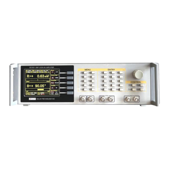
Fig.9 Front Panel of SE2031 Display The SE2031 uses a 5.6-inch TFT-LCD for display and interactive control. The resolution of the display screen. And the display screen has 8 levels background brightness which can set in the [SYSTEM] submenu. The large area in left screen is used for displaying the measurement results of input signal. -
Page 24: Rear Panel
2.2 Rear Panel The rear panel of SE2031 is shown in Fig.10. It includes a cooling fan, a power connector, a power switch, an USB interface and extended functional interfaces. The extended functional interfaces include AUX IN, AUX OUT, TRIG IN, TTL OUT, and MONITOR. -
Page 25: Main Display
Tel: 886. 909 602 109 Email: sales@salukitec.com www.salukitec.com 2.3 Main Display The main display is divided into 4 parts, including status bars, data bar, monitoring bar and function bar. (1) Status Bars As is shown in Fig.11 and Fig.12, the status bars indicate the current settings of the system or the results of measurement. If [Display] is lighted, see the Status 1. - Page 26 Tel: 886. 909 602 109 Email: sales@salukitec.com www.salukitec.com Fig.12 Main Interface: Status Bar 2 (2) Data Bar Fig.13 Main Interface: Data Bar Users can choose which to display among <X>, <Y>, <R>, <θ> in [DISPLAY] submenu, as shown in Fig.13. How to display is also optional, such as number chart, bar chart, XY coordinate graph and pole coordinate graph.
- Page 27 Tel: 886. 909 602 109 Email: sales@salukitec.com www.salukitec.com If there are both an input overload and amplification overload, it shows <Overload: INPUT GAIN>. In this case, reduce the input as soon as possible to prevent over-voltage damage to the instrument. <Freq>...
- Page 28 Tel: 886. 909 602 109 Email: sales@salukitec.com www.salukitec.com As is shown in Fig.15, users can choose different functions in the function bar. It’s operated by 5 soft keys which are make different sense in different submenu. This is the basic way to control the system.
-
Page 29: Menus
Tel: 886. 909 602 109 Email: sales@salukitec.com www.salukitec.com 3 Menus The MENUs consists of ten parts: [INPUT/FILTERS], [REF/PHASE], [GAIN/TC], [DISPLAY], [SAVE/LOAD], [CHANNEL OUTPUT], [SAMPLE], [AUX OUTPUT], [SYSTEM] and [AUTO SET]. Press one button and then the interface will switch to the corresponding sub menu display. 3.1 [INPUT/FILTERS] You can enter this submenu by choosing the [INPUT/FILTERS] in menus of front panel, as is shown in Fig.16.. -
Page 30: Ref/Phase]
Tel: 886. 909 602 109 Email: sales@salukitec.com www.salukitec.com between the signal and instrument ground and the input current ability of the signal ground is strong, it is necessary to use <Float> and make the signal ground float. This can also limit current to protect the system circuit. 3.1.4 <... - Page 31 Tel: 886. 909 602 109 Email: sales@salukitec.com www.salukitec.com Fig.18 [REF/PHASE] Submenu-<Internal> Fig.19 [REF/PHASE] Submenu-<Internal Sweep> 3.2.1 < Ref. phase >: Setting the Reference Phase Spinning the knob or press the two buttons under the knob to set the phase difference between two orthogonal reference signals.
- Page 32 Tel: 886. 909 602 109 Email: sales@salukitec.com www.salukitec.com <Internal Sweep> The internal reference signal sweep. In this mode, the signal generator will conduct internal sweep according to the parameters set by users. As is shown in Fig.19, <Sweep> can be set. 3.2.3 <...
- Page 33 Tel: 886. 909 602 109 Email: sales@salukitec.com www.salukitec.com <Sweep Type> Setting frequency sweep type. <Linear> linear sweep type <Log> logarithm sweep type In the <Linear> mode, the step type is frequency by adding the frequency with the setting step frequency. In the <Log>...
- Page 34 3.2.7 < Sine Output>: Setting the Sine Output SE2031 can output sine wave whose amplitude range is from 0.001Vpp to 10Vpp through the “Sine Out” BNC connector on front panel. <Fixed> fixed amplitude output, <Linear> linear sweep amplitude output or <Log>...
- Page 35 When using the <External> reference, <Sine Output> provides a sine signal which locks phase with external reference. When using the <Internal> reference, the reference signal is generated by the oscillator in SE2031. The “TTL OUT” BNC connector on rear panel will output TTL signal which is synchronous with the <Sine Output>.
-
Page 36: Gain/Tc]
When start from <Single> sweep, SE2031 does an internal amplitude sweep according to the settings of users. After that, the status jumps back to <Stop> automatically. When start from <Loop > sweep, SE2031 does constant loop sweep until users switch the status to <Stop> manually. - Page 37 Tel: 886. 909 602 109 Email: sales@salukitec.com www.salukitec.com Fig.24 [GAIN/TC] Submenu 3.3.1 < Sensitivity>: Setting the Full Scale Sensitivity Choose an appropriate full-scale sensitivity according to the amplitude of the input signal. Adjust the value through the soft keys or spin knob. Table 1.
- Page 38 Tel: 886. 909 602 109 Email: sales@salukitec.com www.salukitec.com <Sensitivity> and <Reserve> can be combined into different dynamic reserve and input gain, the relationship is shown in Table 2. Table 2. Dynamic Reserves and Gain relation table Dynamic Reserves(dB) Gain Sensitivity Low Noise Normal High Reserve Low Noise Normal...
-
Page 39: Display]
Tel: 886. 909 602 109 Email: sales@salukitec.com www.salukitec.com Table 3. Time Constants 10 μs 3 ms 300 s 30 μs 10 ms 1000 s 100 μs 30 ms 10 s 3000 s 300 μs 100 ms 30 s 1 ms 300 ms 100 s The greater the time constant is, the smaller the ENBW is, the longer the system response is and the higher the... - Page 40 Tel: 886. 909 602 109 Email: sales@salukitec.com www.salukitec.com Fig.25 [DISPLAY] Submenu 3.4.1 < Monitor >: Setting Status Bar Display <Settings> The current setting parameters and status will be shown in the status bar at the top left of the screen, such as <Sensitivity>, <Filter>...
- Page 41 Tel: 886. 909 602 109 Email: sales@salukitec.com www.salukitec.com Fig.27 <Full>-<Chart> Display Fig.28 <Full>-<List> Display <Area>: Setting Display Area <Full> Full display mode displays in the whole dynamic area. It has 4 display types, including <Polar>, <Chart>, <FFT> and <List>. 1) <Polar>: polar chart The graphical pointer can change its length according to the actual <R>...
- Page 42 Tel: 886. 909 602 109 Email: sales@salukitec.com www.salukitec.com Fig.29 <Top>-<Bar> Display Fig.30 <Top>-<Chart> Display <Top> Only choose the top area to set. When <Type> or <Trace> is changed, the display way of top area will change, as is shown in Fig.29 and Fig.30. There are two choices in <Type>, including <Bar>...
- Page 43 Tel: 886. 909 602 109 Email: sales@salukitec.com www.salukitec.com and Equation. <X> The X value of fundamental wave of the input signal. <Y> The Y value of fundamental wave of the input signal. <R> The R value of fundamental wave of the input signal. <θ>...
- Page 44 Tel: 886. 909 602 109 Email: sales@salukitec.com www.salukitec.com Fig.31 <Equation> Secondary Submenu <Equation> Setting equation parameters. The value of A, B and C in equation 1 ~ 4=A*B/C can be changed through soft keys. There are 4 numeric options, including fundamental wave, harmonic wave, frequency and constant parameter, as is shown in Fig.31.
-
Page 45: Save/Recall]
Tel: 886. 909 602 109 Email: sales@salukitec.com www.salukitec.com Fig.32 <Disp More> Secondary Submenu <Range> Setting display range <Range> is used to set the largest scale of <Bar>, <Chart> and <Polar> chart. The input range of <Range> is 1 nV to 1 V. This range will change in sync with the change of <Sensitivity>. -
Page 46: Channel Output]
Tel: 886. 909 602 109 Email: sales@salukitec.com www.salukitec.com Fig.33 [SAVE/RECALL] Submenu [SAVE/RECALL] menu is mainly used to save and recall the setting parameters and status. Users can save in <S1>, <S2>, <S3> and <S4> according to their individual favorites. As is shown in Fig.33, <Save & Recall> choose <Save>, <Channel>... - Page 47 Tel: 886. 909 602 109 Email: sales@salukitec.com www.salukitec.com Signal(sou rce) offset Expand Output Sens 2. When source is <θ>, <θh1>, <θh2> Signal(sou rce) Output 3. When source is <E1> to <E4> (Equation), there are other options as below: a) AUX_IN1~AUX_IN4: the output voltage is equal to the input voltage.
- Page 48 Tel: 886. 909 602 109 Email: sales@salukitec.com www.salukitec.com <X>: the corresponding analog level of the channel output X <Y>: the corresponding analog level of the channel output Y <R>: the corresponding analog level of the channel output R <θ>: the corresponding analog level of the channel output θ <Xh1>: the corresponding analog level of the channel output Xh1 <Yh1>:...
-
Page 49: Sample]
Tel: 886. 909 602 109 Email: sales@salukitec.com www.salukitec.com 3.6.3 < Speed >: Setting the Output Speed Choose the < Offset & Expand> and enter the secondary submenu, as is shown in Fig.35. <Slow> the data output speed of channel CH1 & CH2 is 10 Hz <Fast>... - Page 50 <Buffer1~4> Setting the 4 sampling buffers There are 4 internal <Buffer> in SE2031. Each buffer can store 16384 34-bits-data. Each buffer can store any one of the following parameter, including <R>, <X>, <Y>, <θ>, <R>, <X>, <Y>, < θ>, <R>, <X>, <Y>, < θ>, <Noise>, <E1>, <E2>, <E3>, <E4>, <A1>, <A2>, <A3>, <A4>...
-
Page 51: Aux Output]
The forth channel output of AUX DAC, corresponding to AUX_DAC4 on rear panel. [SYSTEM] [SYSTEM] submenu includes the system information and settings of SE2031, like instrument information, screen brightness and the settings of RS232 communications, as is shown in Fig.39. - Page 52 3.9.1 < Info >: Setting the Parity Mode Choose <Info> to enter a secondary submenu shown in Fig.40. This submenu displays related information about the R&D unit of the instrument. Fig.40 <INFO>-Submenu Choose <Version> and the interface displays the version of SE2031, as is shown in Fig.41.
- Page 53 Tel: 886. 909 602 109 Email: sales@salukitec.com www.salukitec.com Fig.41 <INFO>-Version Choose <Contact> and the interface displays contact information as is shown in Fig.42. Fig.42 <INFO> -Contact Information 3.9.2 < Screen > Submenu Fig.43 <Screen> Submenu-<Style 1>...
- Page 54 Tel: 886. 909 602 109 Email: sales@salukitec.com www.salukitec.com Fig.44 <Screen> Submenu-<Style 2> Choose <Screen> to enter this interface, as is shown in Fig.43 and Fig.44. This submenu includes two function settings, <Window Color> and <Backlight>. setting the window color <Window Color> the window main color is yellow <Style 1>...
-
Page 55: Auto Set]
<ODD> <NONE> nothing Note that using <USB> and <RS232>, the local SE2031 can communicate with another SE2031 or the PC. More details are talked at ‘CHAPTER 4 REMOTE PROGRAMMING’. 3.9.4 < Reset? >: The Lock-in Reset Press the corresponding soft key and the system will be restarted. -
Page 56: Control]
R. The principle is that the system should choose an appropriate <Sensitivity> but no more than the maximum sensitivity. The < Auto Gain > function in SE2031 needs some response time (generally less than 5s). If the current R fluctuates a lot, the setting for <... - Page 57 Tel: 886. 909 602 109 Email: sales@salukitec.com www.salukitec.com If press the [PAUSE] button when the sampling is executing. Sampling will be paused. In this case, press the [START/CONT] button and the sampling will be continued. 3.11.2 < PAUSE/CLEAR >: Pause Sampling or Clear Sampling Data The [PAUSE/CLEAR] button has two functions.
-
Page 58: Remote Programming
The SE2031 has a 256-character input buffer and processes commands in the order received. If the buffer fills up, the new commands will cover the oldest and processed commands. - Page 59 Tel: 886. 909 602 109 Email: sales@salukitec.com www.salukitec.com Note that all numeric variables can be expressed in integer, floating point or exponential formats (i.e., the number five can be 5, 5.0, or .5E1). Strings are sent as a sequence of ASCII characters. 4.2.1 Reference and Phase Commands PHAS(?){x} The PHAS command sets or queries the reference phase shift.
- Page 60 Tel: 886. 909 602 109 Email: sales@salukitec.com www.salukitec.com parameter j should make j*f≤3MHz. If the value of j harmonic is more than 3MHz, then j will be set to the maximum value that meets this condition. SLVL(?){x} The SLVL command sets or queries the amplitude of the output synchronous sine wave. The parameter x determines the amplitude of voltage (real number, unit: V).
- Page 61 Tel: 886. 909 602 109 Email: sales@salukitec.com www.salukitec.com θ θh1 θh2 Noise Freq For example, send command “ EQCD 2,0,17 ” and then the Equation 2 will be set as: E2=R*C1/Freq. The EQCD? i command queries the configuration parameters of Equation i. Values are returned as the serial number corresponding to A, B, C with the values separated by commas.
- Page 62 Tel: 886. 909 602 109 Email: sales@salukitec.com www.salukitec.com ICPL(?){i} The ICPL command sets and queries the input coupling. The parameter i selects AC (i=0) or DC (i=1). ILIN(?){i} The ILIN command sets and queries the notch filter status. The parameter i selects to close notch filters (i=0), open the 50Hz notch filter (i=1), open the 50Hz and 100Hz notch filter at the same time (i=2) or open the 100Hz notch filter (i=3).
- Page 63 4.2.5 Display and Output Commands FPOP(?)i{,j} The FPOP command sets and queries the output channel on the front panel of SE2031. The parameter i must be set when sending this command. The parameter i selects CH1 (i=1) or CH2 (i=2) as the output channel. The FPOP i, j command sets output i to quantity j.
- Page 64 Tel: 886. 909 602 109 Email: sales@salukitec.com www.salukitec.com Parameter Noise The parameter x is used to set the offset and the range is -100.00≤x≤100.00. The parameter j is used to set expand and the range is 1 ≤ x ≤ 256. For example, send command “ OEXP 2,50.00,2”...
- Page 65 Tel: 886. 909 602 109 Email: sales@salukitec.com www.salukitec.com (i=4) and Default (i=5). 4.2.7 Auto Set Commands AGAN The AGAN command performs the Auto Gain function. It is the same as pressing the [Auto Gain] key. Auto Gain may take some time if the time constant is long. ARSV The ARSV command performs the Auto Reserve function.
- Page 66 Tel: 886. 909 602 109 Email: sales@salukitec.com www.salukitec.com θh1 θh2 Noise Freq STRG(?){i} The STRG? command sets or queries the trigger way of data sampling. The parameter i selects inner trigger mode <INT> (i=0) or outer trigger mode <EXT> (i=1). SPRM(?){i} The SPRM? command sets or queries the mode of data sampling.
- Page 67 Tel: 886. 909 602 109 Email: sales@salukitec.com www.salukitec.com θh1 θh2 Noise Freq Values are returned as ASCII floating point numbers with units of Volts, degrees or Hz. This command is a query only command. SNAP?i,j,{k,l,m The SNAP? command records the values of no more than 13 parameters at a single instant. ,n,o,p,q,r,s,t,u} For example, SNAP? is a way to query values of <X>, <Y>, <R>, <θ>...
- Page 68 16384 which is the maximum number of data stored in the buffer. 4.2.10 Reset and IDN Commands The RST command is used to reset SE2031 to its default configurations. All internal status and parameters are set to their default conditions and values. Data stored in the buffers will be lost.
-
Page 69: Computer Operation
Now, use a USB cable to connect the PC and the SE2031. If the driver is OK, the connection successes. Note: Win10 system does not need to install USB2.0 driver, directly insert USB cable can successfully connect... - Page 70 1) You need to open the first file “SE2031_Console Drivers” in Fig.47 and start to install just as shown in Fig 50. 2) Double-click the file “ setup.exe ” and start to install the VISA driver of SE2031. Generally, just install it according to the default configuration.
-
Page 71: Software Guide
You can click the button to switch between these two statuses. Note that before the program runs, the Baud rate of the SE2031 should set to 921600bd. Fig.53 (left) Program is running (right) Program stops 2. Connection This part shows you how to connect the PC and the SE2031. - Page 72 Fig.55 Connection Succeeds Wait for a few seconds. If the interface pops up a prompt box like Fig.56, it means that the connection between PC and SE2031 fails. Fig.56 Connection Succeeds Click the button [YES] to check the status of the connection. Now the right of the status window will display the wrong information, as is shown in Fig.57.
- Page 73 Choose the right COM number. If the COM is right, the connection will success after few seconds. Note that when the PC is connected to SE2031 with USB, you can go to “Device Manager” to search “COM and LPT”. In this case, you can know which COM is used to connect currently.
- Page 74 Tel: 886. 909 602 109 Email: sales@salukitec.com www.salukitec.com Fig.59 The Configuration Area of Input Signal Table 3. Input Configuration Input Source Single-Ended Voltage Differential Voltage Current Current Impedance 1MOhm Current Gain (when the input signal is small, the gain is 10 V/A ) 100MOhm Current Gain (when the input signal is small, the gain is 10 V/A)
- Page 75 Tel: 886. 909 602 109 Email: sales@salukitec.com www.salukitec.com After changing the settings, you need to click to finish this configuration. Otherwise the settings are void. 4. Reference and Frequency Sweep Configuration Reference Signal Configuration: The configuration area of reference signal is shown in the red box in Fig.60. The details of configuration are shown in Table 4.
- Page 76 Tel: 886. 909 602 109 Email: sales@salukitec.com www.salukitec.com Frequency Sweep Configuration: Choose the button to configure internal frequency sweep as is shown in Fig 61. The details of configuration are shown in Table 5. Fig.61 The Configuration Area of Internal Frequency Sweep Table 5.
- Page 77 Tel: 886. 909 602 109 Email: sales@salukitec.com www.salukitec.com 5. Dynamic Reserve and Sensitivity Configuration The configuration area of Dynamic Reserve and Sensitivity is in the red box in Fig.62. The details of configuration are listed on the Table 6. Fig.62 The Configuration Area of Dynamic Reserve and Sensitivity Table 6.
- Page 78 The button will switch to be processing after click the button . This means the SE2031 is executing the auto function. After finishing this process, this button will reset to the start status . And then the “dynamic reserve” and “sensitivity” will refresh to the value that SE2031 returns.
- Page 79 The configurations of “Sync Filter” is relatively independent. Click the corresponding not the button to close or open the auto function. The button will switch to when click the button .This means the SE2031 is executing the auto function. If you need to close the...
- Page 80 Tel: 886. 909 602 109 Email: sales@salukitec.com www.salukitec.com sync filter, click this button again and it will reset to the start status . This means you have closed the sync filter successfully. 8. Output Configuration The output configuration is in the red box in the Fig.65. The details of configuration are shown in Table 9. Fig.65 The Configuration Area of Output Channel Table 9.
- Page 81 Tel: 886. 909 602 109 Email: sales@salukitec.com www.salukitec.com After changing the settings, you need to click to finish this configuration. Otherwise, the settings are void. 9. Aux Output Configuration The sine output configuration is in the red box in the Fig.66. The details of configuration are shown in Table 10. Fig.66 The Configuration Area of Aux Output Channel Table 10.
- Page 82 Tel: 886. 909 602 109 Email: sales@salukitec.com www.salukitec.com Fig.67 The Configuration Area of Equation Table 11. Equation Configuration Options Equation The output of Equation can be E1/E2/E3/E4. The input can be the X/Y/R/ θ of signal or signal harmonic, the ADC1/ADC2/ADC3/ADC4 of AUX_ADC input, noise, frequency and C1/C2.
- Page 83 Tel: 886. 909 602 109 Email: sales@salukitec.com www.salukitec.com Fig.68 The Configuration Area of Sine Output Table 12. Sine Output Configuration Options Sine Out Mode Fixed Linear Sine Out Voltage (Vrms) The Sine Out Mode is Fixed manually. The peak-peak voltage is 1mVrms to 5Vrms, the minimum resolution is 1mVrms.
- Page 84 12. Save Data The software has the function of data storage. Users can choose to save the data or not that SE2031 collects in a period. The saved data contains the X/Y/R/θ of measure signal or signal harmonic, frequency, noise and the ADC1/ADC2/ ADC3/ADC4 of 4 AUX_ADC inputs.
-
Page 85: Usage Examples
This example will show how to use SE2031 PC software to configure parameters, and observe and record the value of R/X/Y/θ. First, connect the SE2031 and PC according to the software usage guidance in 5.2 and then you can start to configure. - Page 86 If you use “ Auto Phase ” to set phase shift angle automatically, you need to click the corresponding button . When this button is clicked and it displays “being progressing”. The SE2031 will execute the auto phase function. After finishing this function, this button will reset to the original status .
- Page 87 If you use sync filter, click the corresponding button . When this button is clicked and it displays “Open”, the SE2031 has started the sync filter function. Click this button again and it will reset to the original status “...
- Page 88 Use “ ” to set sensitivity. Click the button in Auto Sensitivity option. Then this button displays “Processing…” This means the SE2031 is executing auto sensitivity function. And after finishing . Now the “ ” and this function, this button will reset to the original status “...
- Page 89 Tel: 886. 909 602 109 Email: sales@salukitec.com www.salukitec.com Compare the two SE2031 interfaces before and after configuration as is shown in Fig.76 and Fig.77, and you will see the configurations are successful. Fig.79 <SENS> is 100 mV before configuration Fig.80 <SENS> is 50 mV before configuration 5.
- Page 90 As is shown in Fig.78, click the button in the red box. When this button is clicked and it displays “ ”. This means the SE2031 is saving data, as is shown in Fig.79. Fig.79 The data saving is executing...
-
Page 91: Performance Tests
6 Performance Tests Introduction The performance tests are designed for users to prove that the SE2031 can operate normally and enhance users’ confidence to our instrument. Each test can be recorded on the Performance Test Record form at the final section of this chapter. -
Page 92: Self-Test
Tel: 886. 909 602 109 Email: sales@salukitec.com www.salukitec.com Accuracy ≤ 0.005 % Recommended KEITHLEY 2100 3.DC Voltage Source Voltage Range ≥ 10 V Accuracy < 10mVpp Recommended RIGOL DP831A 4.Feedthrough Terminations Impedance 50 Ω Front Panel Display First, turn on the power switch on the rear panel to start the device. Second, Test check whether the display is lighted or not. -
Page 93: Common Mode Rejection
Tel: 886. 909 602 109 Email: sales@salukitec.com www.salukitec.com <Ref. Source> Set to <Internal> <Ref. Frequency> Set to 1Hz <Sensitivity> Set to <1mV> through the spinning knob 3. Wait 10 seconds, then record the value of R. 4. Change the setting: <Coupling>... -
Page 94: Amplitude Accuracy And Flatness
Tel: 886. 909 602 109 Email: sales@salukitec.com www.salukitec.com 6.4 Amplitude Accuracy and Flatness This test measures the amplitude accuracy and frequency response. Device Use the function signal generator to provide an accurate frequency and a sine wave. Use one cable with BNC connector to connect the output of the function signal generator to the A input of the lock-in. -
Page 95: Amplitude Linearity
Tel: 886. 909 602 109 Email: sales@salukitec.com www.salukitec.com 96 kHz 120 kHz a) Set <Sensitivity> of the lock-in to <200 mV>. b) Set the frequency of the function signal generator to 1 kHz and the amplitude to 200.00mVrms. c) Set the frequency of the function signal generator in the upper sequence. d) Wait 10 seconds, then record <R>, then test the next frequency. -
Page 96: Frequency Accuracy
Tel: 886. 909 602 109 Email: sales@salukitec.com www.salukitec.com a) Set the output amplitude of the function signal generator. b) Wait 10 seconds, then record <R>, then test next amplitude. c) Repeat from 3)-a) to 3)-b) until all amplitudes are tested over. 4. -
Page 97: Dc Outputs And Inputs
Tel: 886. 909 602 109 Email: sales@salukitec.com www.salukitec.com b) Set <Sensitivity>. c) Wait 10 seconds, then record <R>, then test next group of Sensitivity-Sine Output. 4. Repeat from 3)-a) to 3)-c) until all the Sensitivity-Sine Output are tested over. Frequency response is checked at frequencies above 1 kHz. - Page 98 Tel: 886. 909 602 109 Email: sales@salukitec.com www.salukitec.com 0.00 -50.00 -100.00 c) Waiting for 10 seconds and record the reading of the DVM. Then, test next group data. d) Repeat steps 3-b) to 4-c) until finishing the tests for CH1. Then, connect the DVM to CH2 and continue to finish the tests for CH2.
-
Page 99: Input Noise
3. Wait until the reading is steady, and then record the maximum value of noise. 4. End the test and fill the result in the performance test form. 6.10 SE2031 Performance Test Record SE2031 Performance Test Record Serial Number Tested By... - Page 100 Tel: 886. 909 602 109 Email: sales@salukitec.com www.salukitec.com 3. Common Mode Rejection Frequency Reading Upper Limit 100Hz 30μV 4. Amplitude Accuracy and Flatness Sensitivity Amplitude Lower Limit Reading Upper 1.0000Vrms 0.9800V 1.0200V 200mV 200.00Vrms 198.99mV 202.00mV 100mV 100.00Vrms 98.00mV 102.00mV 20mV 20.000Vrms 19.60mV...
- Page 101 Tel: 886. 909 602 109 Email: sales@salukitec.com www.salukitec.com SINE OUT Frequency Lower Limit Reading Upper Limit 2.000Vpp 24 kHz 0.6859V 0.7283V (0.7071Vrms) 48 kHz 0.6859V 0.7283V 72 kHz 0.6859V 0.7283V 96 kHz 0.6859V 0.7283V 8. DC Outputs and Inputs Output Offset Lower Limit Reading...
- Page 102 Tel: 886. 909 602 109 Email: sales@salukitec.com www.salukitec.com 0.00 -0.020V 0.020V -5.00 -5.100V -4.900V -10.00 -10.300V -9.700V Output Voltage Lower Limit Reading Upper Limit AUX OUT 4 10.00 9.700V 10.300V 5.00 4.900V 5.100V 0.00 -0.020V 0.020V -5.00 -5.100V -4.900V -10.00 -10.300V -9.700V Input...
- Page 103 Tel: 886. 909 602 109 Email: sales@salukitec.com www.salukitec.com Input Noise Frequency Sensitivity Reading Upper Limit 1 kHz 100nV 15 nV/ √Hz...
-
Page 104: Operation Examples
7.1 Simple Signal Measurements This example will show how the SE2031 measure the value of R, X, Y, θ. You need two BNC cables to input the measurement signal and the reference signal. In this case, we use the function signal generator to generate a 80mVrms, 1kHz sine signal and use the SE2031 to measure it. - Page 105 When the input of the preamplifier is overload, you should decrease the output amplitude of the function signal generator. If the output gain is overload, you should increase the sensitivity of the SE2031 (the input of the preamplifier will be overload when the peak value is larger than 1.7V or the valley value is lower than -1.7V). The default sensitivity is <100mV>.
- Page 106 Tel: 886. 909 602 109 Email: sales@salukitec.com www.salukitec.com Press the knob to choose <Sens> and then <Sens> will be lighted. Spin the knob to change <Sens> so that there is no overload and the full scale is the maximum. In this case, you need to adjust these parameters like Fig.84. The result of measurement is: R=80.08 mV, θ=0.18°.
- Page 107 Tel: 886. 909 602 109 Email: sales@salukitec.com www.salukitec.com Soft Key 1 Soft Key 2 Soft Key 3 Soft Key 4 Soft Key 5 Fig.86 [DISPLAY] Menu Interface You can change the display way according to steps below. Change the display <R> in top area to display the <θ> with XY Coordinates Chart. First, press the [soft key 2] to choose <Top>;...
-
Page 108: Harmonics Measurements
Use a BNC cable to connect the output of the function signal generator and the A/I input of the SE2031. Use another BNC cable to connect the reference signal of the function signal generator and the REF IN of the SE2031, as is shown in Fig.89. - Page 109 Tel: 886. 909 602 109 Email: sales@salukitec.com www.salukitec.com Fig.90 Measured Signal Parameter 4. Press [REF PHASE] in front panel and set <Harmonic> to the required order, as is shown in Fig.91. Fig.91 [REF PHASE] Submenu...
- Page 110 Tel: 886. 909 602 109 Email: sales@salukitec.com www.salukitec.com Soft Key 1 Soft Key 2 Soft Key 3 Soft Key 4 Soft Key 5 Fig.92 REF PHASE Submenu Set the harmonic number in <Harmonic> secondary submenu and use keyboard to choose times. The operation method of measuring the first and third harmonic of the input square wave is below, as is shown in Fig.92.
- Page 111 Tel: 886. 909 602 109 Email: sales@salukitec.com www.salukitec.com Fig.94 The 3 Harmonic Measurement Result How to get the amplitude of the n harmonics How to calculate the harmonic theoretical value of the square wave: suppose that the peak-peak value of square value is E and the angular frequency is ω.
-
Page 112: Optical Spectral Measurements
Use a BNC cable to connect the Sync out f1 of the optical chopper and the REF IN of the SE2031. Use a BNC cable to connect the data collection platform and the CH1 OUT of the SE2031. The sketch is shown in Fig.95. - Page 113 Fig.95 Spectral Measurement Platform Diagram Fig.96 Spectral Measurement Platform Physical Connection 4. Start the spectral measurement and collect data from the data collection platform. Then, you will get an uncalibrated spectral curve as is shown in Fig.97. Fig.104 Spectrum Curve measured by SE2031...
-
Page 114: Serial Communication
Note that this software can set the communication mode, the receiver mode, the transfer mode. The default Baud rate of the SE2031 is 921600. The SE2031 has no parity bit, 8 data bits and 1 stop bit. The port number choose the COM number automatically assigned by the PC. - Page 115 Tel: 886. 909 602 109 Email: sales@salukitec.com www.salukitec.com Fig.99 “CommUart Assistant” Software Display After these settings are completed, if you see a black circle like , you need to click the button to make it red like . If you cannot make it red, please check the port number and repeat the connection. If the connection id OK, you will see Fig.101.
- Page 116 Tel: 886. 909 602 109 Email: sales@salukitec.com www.salukitec.com The port number is COM5 Fig.100 Check the port number at “Device Manager” Select COM5 port number Select the default baud rate 921600 Open and close buttons Fig.101 USB connection succeeds...
- Page 117 Tel: 886. 909 602 109 Email: sales@salukitec.com www.salukitec.com 4. Transfer commands to communicate with the SE2031. (1) The commands consist of four upper mnemonics, option parameters and a terminator. Several commands at the same line are separated by semicolons. More details please see Chapter 4 Remote Programming. The terminator can be a carriage return <cr>...
- Page 118 Tel: 886. 909 602 109 Email: sales@salukitec.com www.salukitec.com Hex display, return the parameters with 0X0D. Hex display can see the return parameter after the 0X0D. Selecting this item will cause the ASC II in the send area to be converted to a hex format display. After the instruction to be added 0X0D.
- Page 119 Tel: 886. 909 602 109 Email: sales@salukitec.com www.salukitec.com Can return parameters normally. Select the fixed byte, set the value to 0D. No additional carriage return 0xD is required. Fig.104 Setting the checksum (3) Multiple commands are separated by “,”, such as “SENS 24;FMOD 1;FREQ 1000;SENS ?;FMOD ?; FREQ ?”, as is shown in Fig.105.
- Page 120 Fig.106 and Fig.107. Note that when use this software to control the SE2031, the LCD display will refresh at the same time. For example, if <Sens: 100mV> is corresponding to the “25” command. <Sens> will change to <Sens: 50mV> when the SE2031 receives the “24”...
- Page 121 Tel: 886. 909 602 109 Email: sales@salukitec.com www.salukitec.com Continuously receives the returned R value data Set the data cyclic to send The transmission interval is set to 200ms Send an instruction to read the R value Fig.106 Read the single R value continuously...
- Page 122 Tel: 886. 909 602 109 Email: sales@salukitec.com www.salukitec.com Continuously return the value of X,Y,R,θ Send multiple values read instruction, Separated the parameters by comma. Fig.107 Read the Values of X, Y, R, θ and Freq continuously --END OF DOCUMENT--...
Need help?
Do you have a question about the SE2031 and is the answer not in the manual?
Questions and answers