Table of Contents
Advertisement
Quick Links
Advertisement
Table of Contents

Related Manuals for Saluki SE1201


Summary of Contents for Saluki SE1201
- Page 1 SE1201 Digital Lock-in Amplifier User Manual Saluki Technology Inc.
- Page 2 Tel: 886. 909 602 109 Email: sales@salukitec.com www.salukitec.com The document applies to following models: SE1201 DSP Lock-in Amplifier (50 mHz to 120 kHz) Standard Pack: 1 × Main Machine 1 × Power Cord 1 × USB Cable ...
- Page 3 Saluki. Saluki Tech owns the copyright of this document which should not be modified or tampered by any organization or individual or reproduced or transmitted for the purpose of making profit without its prior permission, otherwise Saluki will reserve the right to investigate and affix legal liability of infringement.
-
Page 4: Table Of Contents
Tel: 886. 909 602 109 Email: sales@salukitec.com www.salukitec.com Content 1 Lock-in Amplifier Basics............................6 Introduction..............................6 Functional Diagram............................8 Reference Channel............................8 Phase Sensitive Detectors..........................9 Time Constants and DC Gain........................10 DC Outputs and Scaling..........................11 Dynamic Reserve............................13 Signal Input Amplifier and Filters........................14 Input Connections............................16 1.10 Intrinsic Noise Sources..........................16 1.11 External Noise Sources.......................... - Page 5 Tel: 886. 909 602 109 Email: sales@salukitec.com www.salukitec.com Common Mode Rejection..........................62 Amplitude Accuracy and Flatness........................62 Amplitude Linearity............................. 64 Frequency Accuracy.............................65 Sine Output Amplitude Accuracy and Flatness................... 65 DC Outputs and Inputs..........................66 Input Noise..............................67 7 Operation Examples...............................70 Simple Signal Measurements........................70 Harmonics Measurements..........................
-
Page 6: Lock-In Amplifier Basics
Tel: 886. 909 602 109 Email: sales@salukitec.com www.salukitec.com 1 Lock-in Amplifier Basics 1.1 Introduction The Lock-in amplifier is a device used to detect very small signals, which are always obscured by noise sources many thousands of times lager. The lock-in amplifier can extract these small signals from noises and measure their values accurately. - Page 7 Tel: 886. 909 602 109 Email: sales@salukitec.com www.salukitec.com sin( sin( sin( cos( cos( sin( In the time region, the output of the PSD consists three parts: The first part is a DC signal.
-
Page 8: Functional Diagram
1.2 Functional Diagram The functional block diagram of the SE1201 DSP Lock-In Amplifier is shown in Fig.4. On the whole, the SE1201 includes signal conditioners, reference signal generators, an algorithm module and a system control module and so on. -
Page 9: Phase Sensitive Detectors
PSD, the output is not a single frequency, but a distribution of frequencies about the true reference frequency. In fact, phase noise in the SE1201 is very low and generally has no effect. In applications that requiring no phase jitter, the internal reference mode should be chose. -
Page 10: Time Constants And Dc Gain
To the digital PSD's, the dynamic reserve is limited by the quality of the A/D conversion. Once the input signal is digitized, no further errors are introduced. Practically, the dynamic reserve of SE1201 can exceed 120dB. The performance of a lock-in amplifier is largely determined by the performance of its PSD's. Almost in all respects, the digital PSD outperforms the analog one. -
Page 11: Dc Outputs And Scaling
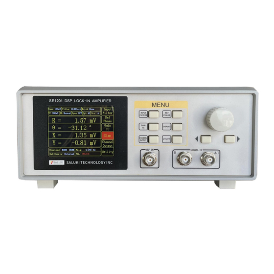
The SE1201 has Channel 1 and Channel 2 outputs (CH1 and CH2) on the front panel. CH1 and CH2 Outputs and Display The output range of CH1 and CH2 is from ±5V. The output signal is proportional to the value of the test signal and the setting scale. Otherwise, the SE1201 shows the... - Page 12 CH1 and CH2 on the front panel, including the value of X, Y, R, θ of the test signal. The display interface of SE1201 is shown in Fig.6. SE1201 can display the value of CH1 and CH2 through bars in addition to numbers. To discover the changes of data, you can observe the data in the time region.
-
Page 13: Dynamic Reserve
Tel: 886. 909 602 109 Email: sales@salukitec.com www.salukitec.com Fig.7 [Channel Output] Submenu 1.7 Dynamic Reserve The definition of dynamic reserve is the ratio of the largest tolerable noise signal to the full scale signal, expressed in dB, which is defined as: Dynamic reserve = 20Lg(OVL/FS)(dB) Here OVL is the total dynamic range of the input signal. -
Page 14: Signal Input Amplifier And Filters
Input noise works in the same way. For sensitivities below 5μV, the value of input noise determines the output noise. ENBW depends on the time constant and filter roll off. For example, suppose the SE1201 is set to <5 μV> full scale, <100... - Page 15 Notch Filters There are two notch filters in the signal amplifier chain in SE1201. They are pre-tuned to the line frequency and twice the line frequency. When the largest noise signals are at the power line frequencies, these filters can remove noise signals at these frequencies.
-
Page 16: Input Connections
Tel: 886. 909 602 109 Email: sales@salukitec.com www.salukitec.com 1.9 Input Connections Noises always exist in all circuits. Even if the signal is not very weak, noises exist and decrease the accuracy of measurement. There are many methods to reduce noise. Minimizing the various noise sources can increase the accuracy of the measurement. - Page 17 Tel: 886. 909 602 109 Email: sales@salukitec.com www.salukitec.com Every resistor generates a noise voltage across its terminals due to thermal fluctuations in the electron density within the resistor itself. This is Johnson noise. The spectrum of the Johnson noise is flat, so the noise power is almost the same in different frequency band (of course there is an upper limit frequency).
-
Page 18: External Noise Sources
Tel: 886. 909 602 109 Email: sales@salukitec.com www.salukitec.com is caused by the random value of contact resistance between two conductors. The current amplitude of 1/f noise follows the Gaussian distribution, and the power spectrum density is proportional to 1/f which is given by: ... - Page 19 Tel: 886. 909 602 109 Email: sales@salukitec.com www.salukitec.com 1) Remove or turn off the noise source. 2) Design the experiment to measure voltages with low impedance for most of low frequency noise sources. 3) Install capacitive shielding by placing the experiment and detector in one metal box. Inductive Coupling An AC current in a nearby piece of apparatus can couple to the experiment via a magnetic field.
-
Page 20: Harmonic Detection
The base frequency component is the base wave. The multiple frequencies are harmonics. The SE1201 can only measure the base wave or one component of the harmonics at one time. The settings of harmonic detection are at <Harmonic> in [REF/PHASE] menu. -
Page 21: Interfaces
2.2 Rear Panel The rear panel of SE1201 is shown in Fig.9. It includes a cooling fan, a power connector, a power switch, an USB interface, a RS232 interface and four BNC connectors. The four BNC connectors are named [SINE OUT], [CH1 OUT],... -
Page 22: Main Display
The SE1201 can communicate with the PC or another SE1201 through a RS232 interface. If it is connected with the PC, the PC can control the SE1201 and read data directly from it. If it is connected with another SE1201, the master SE1201 can read data from the slave SE1201. - Page 23 Tel: 886. 909 602 109 Email: sales@salukitec.com www.salukitec.com <DR> The status of dynamic reserve. <Sync> The status of synchronous filter. <Cpl> The couple mode. <Src> The input mode. <X> The X value of input signal. <Y> The Y value of input signal. <R>...
- Page 24 Tel: 886. 909 602 109 Email: sales@salukitec.com www.salukitec.com current menu. Fig.12 Function bar 1 in [DISPLAY] menu Fig.13 Function bar 2 in [Input Filter] menu (3) Monitoring Bar The monitoring bar is at the bottom of the screen as is shown in Fig.14.
- Page 25 Tel: 886. 909 602 109 Email: sales@salukitec.com www.salukitec.com Fig.14 The highlighted [Disp] bar <Overload> To indicate an input overload or amplification overload. If there is no overload, it shows <Overload: NONE NONE>; If an input overload, it shows <Overload: INPUT NONE>; If an amplification overload, it shows <Overload: NONE GAIN>;...
- Page 26 Tel: 886. 909 602 109 Email: sales@salukitec.com www.salukitec.com Fig.15 The Menu bar at the left portion of the main display...
-
Page 27: Menus
Tel: 886. 909 602 109 Email: sales@salukitec.com www.salukitec.com 3 Menus The MENUs consists of six parts: [INPUT/FILTERS], [REF/PHASE], [GAIN/TC], [DISPLAY], [CHANNEL OUTPUT] and [UTLITY]. 3.1 [INPUT/FILTERS] When press the [INPUT/FILTERS] button, you will enter this following submenu, as is shown in Fig.16. There are 5 function settings in this submenu, including <Source>, <Current Gain>, <Grounding>, <Coupling>... -
Page 28: Ref/Phase]
Tel: 886. 909 602 109 Email: sales@salukitec.com www.salukitec.com Generally, choose <Ground> when the current of the input signal is not large. It prevent signal drift caused by floating. Choose <Float> when there is a large potential difference between the signal ground and chassis ground and a strong current injection. - Page 29 Tel: 886. 909 602 109 Email: sales@salukitec.com www.salukitec.com Users can set the phase shift between two orthogonal reference signals through the keyboard. The accuracy of phase is 0.01°and the range is from -180° to +180°. For phase, it’s meaningful only when there is a reference. In the system, the default reference phase is the phase of REF IN after locked by a high precision PLL.
-
Page 30: Gain/Tc]
Tel: 886. 909 602 109 Email: sales@salukitec.com www.salukitec.com 3.3 [GAIN/TC] Press [GAIN/TC] button, then enter the submenu as is shown in Fig.18. There are 5 function settings in the submenu, including <Sens>, <DR>, <TC>, <Filter > and <Sync>. Fig.18 [GAIN/TC] Submenu 3.3.1 <... -
Page 31: Display]
Tel: 886. 909 602 109 Email: sales@salukitec.com www.salukitec.com 3.3.3 < TC >: Setting the Time Constants The range of time constant is from 10 us to 3000 s. Adjust the value through the left and right buttons and the spin knob. -
Page 32: Channel Output]
Tel: 886. 909 602 109 Email: sales@salukitec.com www.salukitec.com Fig.19 [Disp] Display Submenu [CHANNEL OUTPUT] Press [CHANNEL OUTPUT] button and enter the submenu as is shown in Fig.20. The two BNCs CH1 and CH2 can output R, X, Y and θ that users wanted by setting in the [CHANNEL OUTPUT] submenu. The output offset and expand is set in <Offset &... -
Page 33: Utility]
3.6.5 < Sine Output >: Setting the Sine Output Amplitude SE1201 provides a sine from 0V to ±1V through the “SINE OUT” BNC on the rear panel. The sine out amplitude is adjusted through the knob and the left and right buttons. The available range is from 0.100Vrms to 1.000Vrms with the resolution of 0.001Vrms. - Page 34 Tel: 886. 909 602 109 Email: sales@salukitec.com www.salukitec.com Fig.21 [Utility] Submenu 3.6.1 < StoreRecall>: Store or Recall the Settings of Parameters Choose <StoreRecall> in <UTILITY> and enter the submenu in Fig.22. There are 3 function settings in this submenu, including <StoreRecall>, <Channel> and <Execute>. Fig.22 [StoreRecall] Submenu <StoreRecall>...
- Page 35 Tel: 886. 909 602 109 Email: sales@salukitec.com www.salukitec.com <Default> The default archive. Valid only for <Recall>. <Execute> Settings of executing <YES> Executes the current setting Always off (It switches to <NO> automatically when complete executing the current setting.) <NO> Do not execute the current setting. 3.6.2 <...
- Page 36 <Slave> The local SE1201 is set as the slave. Note that use <USB> and <RS232>, the local SE1201 can communicate with another SE1201 or the PC. More details are talked at ‘CHAPPER 4 REMOTE PROGRAMMING’. 3.6.4 < System>: Systems Settings Choose <System>...
- Page 37 Spin the knob to change the brightness from <Level1> to <Level8>. 3.6.5 < Info>: Information View Choose <info> in <UTILITY> and enter the submenu in Fig.26. It shows the version, serial number of this SE1201 and the R&D units’ contact information.
-
Page 38: Remote Programming
The SE1201 has an input buffer that can store up to 50 instructions and processes commands in the order received. When the input buffer is full, errors may occur. Thus, it is better to use no more than 50 commands. - Page 39 Tel: 886. 909 602 109 Email: sales@salukitec.com www.salukitec.com The variables are defined as follows. i, j, k, l, m, n, o, p, q, r, s, t, u integers real numbers frequency Note that all numeric variables can be expressed in integer, floating point or exponential formats (i.e., the number five can be 5, 5.0, or .5E1).
- Page 40 Tel: 886. 909 602 109 Email: sales@salukitec.com www.salukitec.com or DC (i=1). ILIN(?){i} The ILIN command sets and queries the notch filter status. The parameter i selects to close notch filters (i=0), open the 50Hz notch filter (i=1), open the 100Hz notch filter (i=2) or open the 50Hz and 100Hz notch filter at the same time (i=3).
- Page 41 4.2.4 Output Commands FPOP(?)i{,j} The FPOP i command sets and queries the output channel on the front panel of SE1201. The parameter i must be set when sending this command. The parameter i selects CH1 (i=1) or CH2 (i=2) as the output channel. The parameter j is used to select the type of output source.
- Page 42 4.2.8 IDN Commands *IDN? The IDN? command queries the ID of the SE1201. The result returns as “SSI LIA-SE1201, SNXXXXXX, VerXXX”. Here, the first is the model name, such as SE1201. The second is the serial number, such as SN000001. The third is the version number, such as Ver1.00.
-
Page 43: Computer Operation
Tel: 886. 909 602 109 Email: sales@salukitec.com www.salukitec.com 5 Computer Operation 5.1 Install Software The required software is provided with the CD disk as below in Fig.27. Fig.27 Software files 1. Install the UART to USB Driver (1) Double-click “FT232_drive.exe” in Fig. 28 in the fourth file “Uart Driver” in Fig.27 and then you can see the Fig.29, which shows the installation is running. - Page 44 Now, use a USB cable to connect the PC and SE1201. If the driver is OK, they will be linked automatically. Note that if the PC is online, the PC will search the proper driver online when you connect the PC and SE1201. And the installation will run automatically.
-
Page 45: How To Use The Software
In Fig.34, if you see [Connecting] as (left), it means the program is running. If you see [Connect] as (right), it shows the program is broke down. You can click the button to switch between these two statuses. Note that before the program runs, the Baud rate of the SE1201 should set to 921600bd. - Page 46 Fig.34 (left) Program is running (right) Program stops 2. Connection This part shows you how to connect the PC and the SE1201. As is shown in Fig.35, click the button Fig.35 Current Connection Status The program begins to run and search for the proper COM automatically. If the connection succeeds, you will see the version information in Fig.36.
- Page 47 Choose the right COM number. If the COM is right, the connection will success after few seconds. Note that when the PC is connected to SE1201 with USB, you can go to “Device Manager” to search “COM and LPT”. In this case, you can know which COM is used to connect currently.
- Page 48 Tel: 886. 909 602 109 Email: sales@salukitec.com www.salukitec.com The program configuration area of input signal is as shown in the red box in Fig.40. The details of the configuration are listed on Table 3. Fig.40 The Configuration Area of Input Signal Table 3.
- Page 49 Tel: 886. 909 602 109 Email: sales@salukitec.com www.salukitec.com After changing the settings, you need to click to finish this configuration. Otherwise the settings are void. 4. Reference and Frequency Sweep Configuration The configuration area of reference signal is shown in the red box in Fig.41. The details of configuration are shown in Table 4.
- Page 50 Tel: 886. 909 602 109 Email: sales@salukitec.com www.salukitec.com 5. Dynamic Reserve and Sensitivity Configuration The configuration area of Dynamic Reserve and Sensitivity is in the red box in Fig.42. The details of configuration are listed on the Table 5. Fig.42 The Configuration Area of Dynamic Reserve and Sensitivity Table 5.
- Page 51 Tel: 886. 909 602 109 Email: sales@salukitec.com www.salukitec.com 6. Harmonic Configuration The harmonic configuration is in the red box in the Fig.43. The harmonic order is set manually from 1 to 32767. The harmonic frequency is no more than 120 kHz. Fig.43 The Configuration Area of Harmonic Configuration 7.
- Page 52 Tel: 886. 909 602 109 Email: sales@salukitec.com www.salukitec.com Table 6. Filter Configuration Time Constant 10μs 300s 30μs 10ms 1000s 100μs 30ms 3000s 300μs 100ms 300ms 100s Filter Slope 6dB/oct 12dB/oct 18dB/oct 24dB/oct SYNC Filter Disable Enable Note that: The SYNC Filter configuration is controlled by a single button .
- Page 53 Fig.46 The Configuration Area of Sine Out Channel 10. Data Storage The software has the function of data storage. Users can choose to save the data or not that SE1201 collects in a period. The saved data contains the value of X, Y, R, θ and Freq.
-
Page 54: Usage Examples
This example will show how to use SE1201 PC software to configure parameters, and observe and record the value of R/X/Y/θ. First, connect the SE1201 and PC according to the software usage guidance in 5.2 and then you can start to configure. - Page 55 Tel: 886. 909 602 109 Email: sales@salukitec.com www.salukitec.com Reference Source External reference, 1000Hz Reference Signal Trigger Way TTL rising edge trigger Phase Shift Angle Time Constant of Low Pass Filter 300ms Filter Slope 12 dB/oct Sampling Rate 10Hz The step to finish the configuration in table 8 are as follows: 1.
- Page 56 If you don’t use sync filter, do not click the corresponding button |Close| and just keep it. If you use sync filter, is clicked and it displays “ Open ” , the SE1201 has click the corresponding button . When this button started the sync filter function.
- Page 57 “ Sensitivity ” with other options in default, as is shown in Fig.51. At last, click the button finish the configurations. Fig.51 Reserve & Sensitivity Configuration Compare the two SE1201 interfaces before and after configuration as is shown in Fig.52 and Fig.53, and you will see the configurations are successful. Fig.52 <SENS> is 100 mV before configuration...
- Page 58 Fig.53 <SENS> is 50 mV before configuration 5. These configurations of SE1201 are finished. Other options are in default. Then uses can collect and save data. Fig.54 The data saving is paused As is shown in Fig.54, click the button in the red box.
- Page 59 Tel: 886. 909 602 109 Email: sales@salukitec.com www.salukitec.com Fig.55 The data saving is executing...
-
Page 60: Performance Tests
6 Performance Tests Introduction The performance tests are designed for users to prove that the SE1201 can operate normally and enhance users’ confidence to our instrument. Each test can be recorded on the Performance Test Record form at the final section of this chapter. -
Page 61: Self-Test
Tel: 886. 909 602 109 Email: sales@salukitec.com www.salukitec.com Accuracy ≤ 0.005 % Recommended KEITHLEY 2100 3. DC Voltage Source Voltage Range ≥ 10 V Accuracy < 10mVpp Recommended RIGOL DP831A 4. Feedthrough Terminations Impedance 50 Ω Front Panel Display Test First, turn on the power switch on the rear panel to start the device. -
Page 62: Common Mode Rejection
Tel: 886. 909 602 109 Email: sales@salukitec.com www.salukitec.com <Ref. Frequency> Set to 1Hz <Sensitivity> Set to <1mV> through the spinning knob 3. Wait 10 seconds, then record the value of R. 4. Change the setting: <Coupling> Set to <DC> 5. Wait 10 seconds, then record the value of R. 6. - Page 63 Tel: 886. 909 602 109 Email: sales@salukitec.com www.salukitec.com Device Use the function signal generator to provide an accurate frequency and a sine wave. Use one cable with BNC connector to connect the output of the function signal generator to the A input of the lock-in.
-
Page 64: Amplitude Linearity
Tel: 886. 909 602 109 Email: sales@salukitec.com www.salukitec.com b) Set the frequency of the function signal generator to 1 kHz and the amplitude to 200.00mVrms. c) Set the frequency of the function signal generator in the upper sequence. d) Wait 10 seconds, then record <R>, then test the next frequency. e) Repeat from 4)-c) to 4)-d) until all the frequencies are tested over. -
Page 65: Frequency Accuracy
Tel: 886. 909 602 109 Email: sales@salukitec.com www.salukitec.com 4. End the test and fill the results in the performance test form. 6.6 Frequency Accuracy This test measures the frequency accuracy of the lock-in. Device Use the function signal generator to provide the reference signal. Use one cable with BNC connector to connect the reference signal of the function signal generator to the REF IN of the lock-in. -
Page 66: Dc Outputs And Inputs
Tel: 886. 909 602 109 Email: sales@salukitec.com www.salukitec.com 4. Repeat from 3)-a) to 3)-c) until all the Sensitivity-Sine Output are tested over. Frequency response is checked at frequencies above 1 kHz. Set <Ref. Frequency> in the following sequence: Test Frequencies 24 kHz 48 kHz 72 kHz... -
Page 67: Input Noise
Check the result 3. Wait until the reading is steady, and then record the maximum value of noise. 4. End the test and fill the result in the performance test form. SE1201 Performance Test Record Serial Number Tested By Firmware Revision... - Page 68 Tel: 886. 909 602 109 Email: sales@salukitec.com www.salukitec.com 2. DC Offset Input Coupling Reading Upper Limit 0.500mV 0.500mV 3. Common Mode Rejection Frequency Reading Upper Limit 100Hz 30μV 4. Amplitude Accuracy and Flatness Sensitivity Amplitude Lower Limit Reading Upper Limit 1.0000Vrms 0.9800V 1.0200V...
- Page 69 Tel: 886. 909 602 109 Email: sales@salukitec.com www.salukitec.com 0.800Vrms 72kHz 0.776V 0.824V 0.800Vrms 96kHz 0.776V 0.824V 0.800Vrms 120kHz 0.776V 0.824V 8. DC Outputs Output Offset Lower Limit Reading Upper Limit 100.00 4.850V 5.150V 50.00 2.376V 2.625V 0.00 -0.050V 0.050V -50.00 -2.625V -2.375V -100.00...
-
Page 70: Operation Examples
7.1 Simple Signal Measurements This example will show how the SE1201 measure the value of R, X, Y, θ. You need two BNC cables to input the measurement signal and the reference signal. In this case, we use the function signal generator to generate a 80mVrms, 1kHz sine signal and use the SE1201 to measure it. - Page 71 When the input of the preamplifier is overload, you should decrease the output amplitude of the function signal generator. If the output is overload, you should increase the sensitivity of the SE1201. The default sensitivity is <100 mV>. So in this case it will not overload. If you need to adjust the sensitivity, you should take the steps below.
- Page 72 Tel: 886. 909 602 109 Email: sales@salukitec.com www.salukitec.com Fig.60 GAIN/TC Menu Interface 2. Press [DISPLAY] as below to see <X>, <Y>, <R> and <θ> as Fig.61. Fig.61 [DISPLAY] Menu Interface 3. Press any other buttons except [DISPLAY] to see <X>, <Y>, <R> and <θ> at the upper region of the display as Fig.62.
-
Page 73: Harmonics Measurements
Use a BNC cable to connect the output of the function signal generator and the A/I input of the SE1201. Use another BNC cable to connect the reference signal of the function signal generator and the REF IN of the SE1201, as is shown in Fig.63. - Page 74 Tel: 886. 909 602 109 Email: sales@salukitec.com www.salukitec.com Fig.64 Measured Signal Parameter 4. Press [REF PHASE] in front panel and enter the corresponding submenu, as is shown in Fig.66. Fig.65 [REF PHASE] Submenu Fig.66 [REF PHASE] Submenu Set the harmonic number in <Harmonic> secondary submenu and use the keyboard to input the required order.
- Page 75 Tel: 886. 909 602 109 Email: sales@salukitec.com www.salukitec.com First, press the knob and then spin it to change the harmonic order. For example, the order is set to 3 in Fig.67. Fig.67 Cubic harmonic measurement of square wave How to get the amplitude of the n harmonics How to calculate the harmonic theoretical value of the square wave: suppose that the peak-peak value of square value is E and the angular frequency is ω.
-
Page 76: Optical Spectral Measurements
Use a BNC cable to connect the Sync out f1 of the optical chopper and the REF IN of the SE1201. Use a BNC cable to connect the data collection platform and the CH1 OUT of the SE1201. The sketch is shown in Fig.68. - Page 77 Fig.70 Spectrum Curve measured by SE1201 5. Use the SR830 instead of the SE1201 to measure. Repeat the steps above to run the same experiment. Then you will get another spectral curve as is shown in Fig.71. You can see that these two curves measured by SE1201 and...
-
Page 78: Serial Communication
Note that this software can set the communication mode, the receiver mode, the transfer mode. The default Baud rate of the SE1201 is 921600. The SE1201 has no parity bit, 8 data bits and 1 stop bit. The port number choose the COM number automatically assigned by the PC. - Page 79 Tel: 886. 909 602 109 Email: sales@salukitec.com www.salukitec.com Fig.72 “CommUart Assistant” Software Display After these settings are completed, if you see a black circle like , you need to click the button to make it red like . If you cannot make it red, please check the port number and repeat the connection. If the connection id OK, you will see Fig.74.
- Page 80 The port number is COM5 Fig.73 Check the port number at “Device Manager” Select COM5 port number Select the default baud rate 921600 Open and close buttons Fig.74 USB connection succeeds 4. Transfer commands to communicate with the SE1201.
- Page 81 Enter key, then click the ‘Send’ button, the command will be sent. As shown in Fig.75 and Fig.76. SE1201 Returns the value. Enter the order, with a carriage return at the end. Send and receive bytes.
- Page 82 Tel: 886. 909 602 109 Email: sales@salukitec.com www.salukitec.com Hex display, return the parameters with 0X0D. Hex display can see the return parameter after the 0X0D. Selecting this item will cause the ASC II in the send area to be converted to a hex format display. After the instruction to be added 0X0D.
- Page 83 Tel: 886. 909 602 109 Email: sales@salukitec.com www.salukitec.com Can return parameters normally. Select the fixed byte, set the value to 0D. No additional carriage return 0xD is required. Fig.77 Setting the checksum (3) Multiple commands are separated by “,”, such as “SENS 24;FMOD 1;FREQ 1000;SENS ?;FMOD ?; FREQ ?”, as is shown in Fig.78.
- Page 84 Fig.79. Note that when use this software to control the SE1201, the LCD display will refresh at the same time. For example, if <Sens: 100mV> is corresponding to the “25”command. <Sens> will change to <Sens: 50mV> when the SE1201 receives the “24”...
- Page 85 Tel: 886. 909 602 109 Email: sales@salukitec.com www.salukitec.com Continuously receives the returned R value data Set the data cyclic to send The transmission interval is set to 200ms Send an instruction to read the R value Fig.79 Read the single R value continuously --END OF DOCUMENT--...
Need help?
Do you have a question about the SE1201 and is the answer not in the manual?
Questions and answers