Table of Contents
Advertisement
Quick Links
Advertisement
Table of Contents

Related Manuals for Saluki SE1022D


Summary of Contents for Saluki SE1022D
- Page 1 SE1022D Digital Lock-in Amplifier User Manual Saluki Technology Inc.
- Page 2 Tel: 886. 909 602 109 Email: sales@salukitec.com www.salukitec.com The document applies to following models: SE1022D DSP Lock-in Amplifier (1 mHz to 102 kHz) Standard Pack: 1 × Main Machine 1 × Power Cord 1 × USB Cable ...
- Page 3 Saluki. Saluki Tech owns the copyright of this document which should not be modified or tampered by any organization or individual or reproduced or transmitted for the purpose of making profit without its prior permission, otherwise Saluki will reserve the right to investigate and affix legal liability of infringement.
-
Page 4: Table Of Contents
Tel: 886. 909 602 109 Email: sales@salukitec.com www.salukitec.com Content 1 Lock-in Amplifier Basics............................6 Introduction..............................6 Functional Diagram............................8 Reference Channel............................8 Phase Sensitive Detectors..........................9 Time Constants and DC Gain........................10 DC Outputs and Scaling..........................12 Dynamic Reserve............................13 Signal Input Amplifier and Filters....................... 14 Input Connections............................ - Page 5 Amplitude Linearity............................. 99 Frequency Accuracy..........................100 Sine Output Amplitude Accuracy and Flatness..................100 Outputs of Dual Channels and 4 AUX Inputs....................101 Input Noise..............................102 6.10 SE1022D Performance Test Record......................103 7 Operation Examples............................108 Simple Signal Measurements........................108 Harmonics Measurements..........................112 Optical Spectral Measurements......................... 115...
-
Page 6: Lock-In Amplifier Basics
Tel: 886. 909 602 109 Email: sales@salukitec.com www.salukitec.com 1 Lock-in Amplifier Basics 1.1 Introduction The Lock-in amplifier is a device used to detect very small signals, which are always obscured by noise sources many thousands of times lager. The lock-in amplifier can extract these small signals from noises and measure their values accurately. - Page 7 Tel: 886. 909 602 109 Email: sales@salukitec.com www.salukitec.com sin( sin( sin( cos( cos( sin( In the time region, the output of the PSD consists three parts: The first part is a DC signal.
-
Page 8: Functional Diagram
The phase difference is defined as: 1.2 Functional Diagram The functional block diagram of the SE1022D DSP Lock-In Amplifier is shown in Fig.4. On the whole, the SE1022D includes signal conditioners, reference signal generators, an algorithm module and a system control module and so on. -
Page 9: Phase Sensitive Detectors
PSD, the output is not a single frequency, but a distribution of frequencies about the true reference frequency. In fact, phase noise in the SE1022D is very low and generally has no effect. In applications that requiring no phase jitter, the internal reference mode should be chose. -
Page 10: Time Constants And Dc Gain
To the digital PSD's, the dynamic reserve is limited by the quality of the A/D conversion. Once the input signal is digitized, no further errors are introduced. Practically, the dynamic reserve of SE1022D can exceed 120dB. The performance of a lock-in amplifier is largely determined by the performance of its PSD's. Almost in all respects, the digital PSD outperforms the analog one. - Page 11 Nevertheless, the synchronous filter only filters out the harmonic component of the reference frequency, and the followed filters filter the noise. The SE1022D provides time constants as long as 3000s when the reference frequency is below 200 Hz, which can satisfy most requirements of measurements.
-
Page 12: Dc Outputs And Scaling
X, Y and R Output Offset and Expand The SE1022D has the ability to offset the X, Y and R outputs, which is useful when measuring deviations in the signal around some nominal value. The output can be offset to zero by setting the offset. Then changes in the output can be read directly from the display or output voltages. -
Page 13: Dynamic Reserve
When the output does not exceed the full scale, the SE1022D can expand the output by multiplying with the expansion factor from 1 to 256. The output with offset and expand is:... -
Page 14: Signal Input Amplifier And Filters
A/D converter without degrading the signal to noise ratio (SNR). The analog gain of the SE1022D ranges from roughly 7 to 1000 times. Higher gains do not improve the SNR. - Page 15 Input noise works in the same way. For sensitivities below 5μV, the value of input noise determines the output noise. ENBW depends on the time constant and filter roll off. For example, suppose the SE1022D is set to <5 μV> full scale, <100 ms>...
-
Page 16: Input Connections
102 kHz to 154 kHz and achieves an attenuation of at least 100dB above 154 kHz. Input Impedance The input impedance of SE1022D is 10 MΩ. If a higher input impedance is desired, the SE1022D remote preamplifier must be used so that the SE1022D has the maximum input impedance of 100 MΩ. -
Page 17: Intrinsic Noise Sources
Tel: 886. 909 602 109 Email: sales@salukitec.com www.salukitec.com Differential Connection (A-B) The second method of connection is the differential mode. This mode has two signals cables which connect the signal source and the lock-in's inputs. There are two high impedance power amplifiers in the lock-in. The lock-in measures the voltage difference between the center conductors of the A and B inputs, which can avoid common voltage problems since the shields are ignored. - Page 18 Tel: 886. 909 602 109 Email: sales@salukitec.com www.salukitec.com Because of the discrete nature of the charge carriers, electric current has noise. Noise is generated in the current since there is always some non-uniformity in the electron flow. This noise is called shot noise. It appears as voltage noise when current is passed through a resistor, or as noise in a current measurement.
-
Page 19: External Noise Sources
Tel: 886. 909 602 109 Email: sales@salukitec.com www.salukitec.com 1.11 External Noise Sources In addition to the intrinsic noise sources discussed previously, there are different kinds of external noise sources. Most of these noise sources are asynchronous and not related to the reference. They do not occur at the reference frequency or its harmonics. - Page 20 Tel: 886. 909 602 109 Email: sales@salukitec.com www.salukitec.com These grounding methods can act as a big loop wire. They pick up noises from the environment and generate voltages in the grounding system. The 50 Hz magnetic field of the AC power is a normal noise source that the ground loop always pickup.
-
Page 21: Aux In
Aux In There are four 16-bit high-precision AUX-ADC input channels in SE1022D. The input voltage ranges from - 10 V to + 10 V and the minimum resolution is 0.3 mV. These 4 ADC channels can clamp the input signal and amplify the internal differential signal. -
Page 22: Interfaces
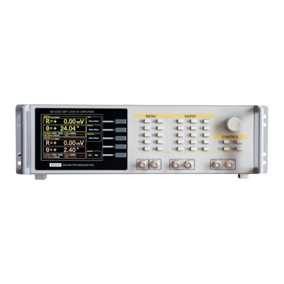
Fig.8 Front Panel of SE1022D Display The SE1022D uses a 5.6-inch TFT-LCD for display and interactive control. Display resolution is 640×480. 8 levels of background brightness are available, which is set in the [SYSTEM] sub-menu. The measurement results are displayed at the left of the screen. -
Page 23: Rear Panel
2.2 Rear Panel The rear panel of SE1022D is shown in Fig.9. It includes a cooling fan, a power connector, a power switch, an USB interface and extended functional interfaces. The extended functional interfaces include SINE OUT, TTL OUT, AUX IN, TRIG IN,CH1&CH2 OUTPUT, and MONITOR. -
Page 24: Main Display
Tel: 886. 909 602 109 Email: sales@salukitec.com www.salukitec.com before the A/D converter and PSD. However, because the analog gain will not be too high, very small signals may not be amplified enough to viewed at the monitor output. 2.3 Main Display The main display is divided into 3 parts, including data bar, monitoring bar and function bar. - Page 25 Tel: 886. 909 602 109 Email: sales@salukitec.com www.salukitec.com <Sens> According to the chosen sensitivity, user can check if the current input signal is too excessive. When the input signal exceeds the sensitivity range, a ‘OVLD’ alert will appear on the upper-right corner of data bar, prompting user to select another appropriate range.
-
Page 26: Menus
The MENUs consists of nine parts: [INPUT/FILTERS], [REF/PHASE], [GAIN/TC], [DISPLAY], [SAVE/LOAD], [CHANNEL OUTPUT], [SAMPLE], [AUTO SET] and [SYSTEM], see the front panel of SE1022D in Fig 9. Each button has an independent corresponding submenu. In each submenu, use soft keys such as[CH A/B SWITCH], [START CONT], [PAUSE CLEAR], [CURSOR], [ACTIVE CHART] to set parameters. -
Page 27: Ref/Phase]
Tel: 886. 909 602 109 Email: sales@salukitec.com www.salukitec.com <Float> The connector shields are isolated from the chassis ground by 10kΩ. <Ground> The connector shields are isolated from the chassis ground by 10Ω and chassis ground is connected to the earth directly. Generally, choose <Ground>... - Page 28 Tel: 886. 909 602 109 Email: sales@salukitec.com www.salukitec.com Fig.14 The [REF/PHASE] Submenu-<External> Fig.15 [REF/PHASE] Submenu-<Internal> Fig.16 [REF/PHASE] Submenu-<Internal Sweep>...
- Page 29 Tel: 886. 909 602 109 Email: sales@salukitec.com www.salukitec.com 3.2.1 < Ref. phase >: Setting the Reference Phase Users can set the phase shift between two orthogonal reference signals through the keyboard. The accuracy of phase is 0.01°and the range is from -180° to +180°. For phase, it’s meaningful only when there is a reference.
- Page 30 Tel: 886. 909 602 109 Email: sales@salukitec.com www.salukitec.com When <Internal Sweep> is chosen in <Ref. source>, this setting can access. Press the <Sweep> button to access the secondary submenu. In the submenu, users can set <Sweep Type>, <Sweep Set> and <Sweep Run>, as is shown in Fig.17.
- Page 31 <Loop> loop sweep When start from <Single> sweep, SE1022D does an internal frequency sweep according to the settings of users. After that, the status jumps back to <Stop> automatically. When start from <Loop> sweep, SE1022D does constant loop sweep until users switch the status to <Stop>...
- Page 32 3.2.7 < Sine Output>: Setting the Sine Output SE1022D can output sine wave whose amplitude range is from 0V to 5V through the “Sine Out” BNC connector on front panel. In its secondary submenu, users can set <Sweep Type>, <Voltage>, <Sweep Set> and <Sweep Run>.
- Page 33 Tel: 886. 909 602 109 Email: sales@salukitec.com www.salukitec.com Fig.20 <Sine Output> Secondary Submenu-<Linear & Log> <Sweep Type> Setting amplitude sweep type. <Fixed> fixed amplitude sweep type(default) <Linear> linear amplitude sweep type <Log> logarithm amplitude sweep type In <Fixed> mode, the amplitude of <Sine Output> is set by users. In <Linear> or <Log> mode, settings are configured in <Sweep Set>...
-
Page 34: Gain/Tc]
<Loop> loop sweep When start from <Single> sweep, SE1022D does an internal amplitude sweep according to the settings of users. After that, the status jumps back to <Stop> automatically. When start from <Loop> sweep, SE1022D does constant loop sweep until users switch the status to <Stop>... - Page 35 Tel: 886. 909 602 109 Email: sales@salukitec.com www.salukitec.com 10 nV/fA 2 μV/pA 500 μV/pA 100 mV/nA 20 nV/fA 5 μV/pA 1 mV/nA 200 mV/nA 50 nV/fA 10 μV/pA 2 mV/nA 500 mV/nA 100 nV/fA 20 μV/pA 5 mV/nA 1 V/μA The charge of <Sensitivity>...
-
Page 36: Display]
Tel: 886. 909 602 109 Email: sales@salukitec.com www.salukitec.com <OFF> Close the synchronous filter. <200Hz> Open the synchronous filter. It’s useful at a low reference frequency (< 200 Hz). When the input signal frequency is very low, the low pass filter can’t get stable results or it needs a long time to do that. - Page 37 Tel: 886. 909 602 109 Email: sales@salukitec.com www.salukitec.com Fig.23 <Full>-<Polar> Display 2) <Chart>: XY coordinates chart. It displays the curve of the measurement results. Users can watch the value of sample points by controlling <Cursor> through spin knob. <Chart> always picks up the measured data cooperating with [SAMPLE] submenu and [CONTROL] area, as is shown in Fig.24.
- Page 38 Tel: 886. 909 602 109 Email: sales@salukitec.com www.salukitec.com Fig.25 <Full>-<List> Display <Top> Only choose the top area to set. When <Type> or <Trace> is changed, the display way of top area will change, as is shown in Fig.26 and Fig.27. There are two choices in <Type>, including <Value>...
- Page 39 Tel: 886. 909 602 109 Email: sales@salukitec.com www.salukitec.com Fig.27 <Top>-<List> Display <Bottom> Only choose the bottom area to set. When <Type> or <Trace> is changed, the display way of bottom area will change, just like the <Top> mode. <Type/Trace> Setting the way of display Switch <Type>...
- Page 40 Tel: 886. 909 602 109 Email: sales@salukitec.com www.salukitec.com <Noise> Noise value of input signal. <E2> The 2th Equation value. <E3> The 3th Equation value. <E4> The 4th Equation value. 3.4.2 <Equation >: Setting the Equation The function of <Equations> is to do basic proportional calculation with the measurement values. The results output through CH1/CH2 BNCs on front panel.
- Page 41 Tel: 886. 909 602 109 Email: sales@salukitec.com www.salukitec.com When <Source> in [CHANNEL OUPUT] submenu choose <E1>, the result of Equation 1 will output. More details are in [CHANNEL OUPUT] submenu. <C1> Setting constant parameter 1. Constant parameter <C1> setting, range: -10 to +10 <C2>...
-
Page 42: Save/Recall]
Tel: 886. 909 602 109 Email: sales@salukitec.com www.salukitec.com [SAVE/RECALL] Press [SAVE/RECALL] button and enter the submenu as is shown in Fig.30. Fig.30 [SAVE/RECALL] Submenu [SAVE/RECALL] menu is mainly used to save and recall the setting parameters and status. Users can save in <S1>, <S2>, <S3>... - Page 43 Tel: 886. 909 602 109 Email: sales@salukitec.com www.salukitec.com Fig.31 [CHANNEL OUTPUT] Submenu The two BNCs CH1 and CH2 can output R, X, Y and θ that users wanted by setting in the [CHANNEL OUTPUT] submenu. The output offset and expand is set in <Offset & Expand>. In <Speed>, users can set the output rate of channel. The calculation equation of output signal is: 1.
- Page 44 Tel: 886. 909 602 109 Email: sales@salukitec.com www.salukitec.com 125 Hz – 200 Hz 250 Hz – 500 Hz 500 Hz – 1000 Hz 1 kHz – 2 kHz 4 kHz – 8 kHz 8 kHz – 16 kHz … Equation is calculated by the above formulas users choose, and then calculate the final result according to the Equation formula itself.
-
Page 45: Sample]
Tel: 886. 909 602 109 Email: sales@salukitec.com www.salukitec.com Fig.32 <Offset & Expand> Submenu <Offset> setting: It is set through keyboard. The adjustable range is -100% to +100%. The minimal step is 0.01% and 0.00% is default. <Expand> setting: It is set through keyboard. The adjustable range is 1 - 256 and 1 is default. If the setting value of Expand causes the calculation result over 10V, the output will be seriously affected. - Page 46 Tel: 886. 909 602 109 Email: sales@salukitec.com www.salukitec.com Fig.33 [SAMPLE] Secondary Submenu 3.7.1 < Step Time >: Setting the Step Time Setting the step time, range: 1ms to 100,000ms, collect one data at every step time. 3.7.2 < Length >: Setting the Sample Length Setting the sample data length, range: 1 to 16384 When the data sampling is being executed, if the <Length>...
-
Page 47: System]
Single and loop sample mode both control sampling to start, stop or reset through the buttons in CONTROL area. [SYSTEM] [SYSTEM] submenu includes the system information and settings of SE1022D, like instrument information, screen brightness and the remote settings of communications, as is shown in Fig.35. - Page 48 3.8.1 < Info >: Setting the Parity Mode Choose <Info> to enter a secondary submenu shown in Fig.36. This submenu displays related information about the R&D unit of the instrument. Fig.36 <INFO>-Submenu Choose <Version> and the interface displays the version of SE1022D, as is shown in Fig.37.
- Page 49 Tel: 886. 909 602 109 Email: sales@salukitec.com www.salukitec.com Fig.37 <INFO>-Version Choose <Contact> and the interface displays contact information as is shown in Fig.38. Fig.38 <INFO> -Contact Information 3.8.2 < Screen > Submenu Choose <Screen> to enter this interface, as is shown in Fig.39 and Fig.40.
- Page 50 Tel: 886. 909 602 109 Email: sales@salukitec.com www.salukitec.com Fig.39 <Screen> Submenu-<Style 1> Fig.40 <Screen> Submenu-<Style 2> This submenu includes two function settings, <Window Color> and <Backlight>. <Window Color> setting the window color <Style 1> the window main color is yellow the window main color is green <Style 2>...
-
Page 51: Auto Set]
Tel: 886. 909 602 109 Email: sales@salukitec.com www.salukitec.com Fig.41 <Remote> Submenu There are 3 function settings in the submenu, including <Remote>, <Baud Rate>, and <Parity>. <Remote> : Setting the communication port. <USB> Use common USB as communication port. <RS232> Use common 9-pin RS-232 connector as communication port. <Baud Rate>... - Page 52 R. The principle is that the system should choose an appropriate <Sensitivity> but no more than the maximum sensitivity. The < Auto Gain > function in SE1022D needs some response time (generally less than 5s). If the current R fluctuates a lot, the setting for <...
-
Page 53: Others]
Tel: 886. 909 602 109 Email: sales@salukitec.com www.salukitec.com [OTHERS] 3.10 3.10.1 < CH A/B SWITCH > Soft key [CH A/B SWITCH] is provided for switching between two channels. Press this soft key to switch from current channel to the other one and configure settings for the other channel. 3.10.2 <... - Page 54 Tel: 886. 909 602 109 Email: sales@salukitec.com www.salukitec.com <Cursor> again. Press the [CURSOR] again when the <Cursor> is already picked on, in this case, the <Cursor> will be hidden afterwards. Spin the knob to move <Cursor>. If the <Cursor> exceeds the edge of <Chart>, the <Chart> will change to the next page. Also, <Cursor>...
-
Page 55: Remote Programming
The SE1022D has a 256-character input buffer and processes commands in the order received. If the buffer fills up, the new commands will cover the oldest and processed commands. - Page 56 Tel: 886. 909 602 109 Email: sales@salukitec.com www.salukitec.com Note that all numeric variables can be expressed in integer, floating point or exponential formats (i.e., the number five can be 5, 5.0, or .5E1). Strings are sent as a sequence of ASCII characters. In addition, parameter i represents which channel is selected.
- Page 57 The parameter j selects harmonic 1(j=1) or harmonic 2 (j=2). The parameter k is an integer from 1 to 32767. The HARMD i,j,k command will set the SE1022D to detect at the the harmonic of reference frequency. The value of k is limited by k*f≤102kHz. If the frequency of the harmonic exceeds102kHz, then j will be set automatically to the maximum value that meets this condition.
- Page 58 Tel: 886. 909 602 109 Email: sales@salukitec.com www.salukitec.com SVSLD(?)i {,x} The SVSLD command sets or queries <Step> amplitude in <Linear> <Sine Output> sweep mode. The parameter i represents the selected channel (A or B). The parameter x indicates the step amplitude (unit:V).The SVSLD? 1 command will return the step amplitude of linear sweeping amplitude mode of channel A.
- Page 59 Tel: 886. 909 602 109 Email: sales@salukitec.com www.salukitec.com Noise Freq For example, send command ‘EQCDD 1,2,0,18,17’ and then the Equation 2 of channel A will be set as follows: E2=R*C1/Freq. The EQCDD? i,j command queries the corresponding channel for the configuration parameters of Equation j.
- Page 60 Tel: 886. 909 602 109 Email: sales@salukitec.com www.salukitec.com selects AC (j=0) or DC (j=1). ILIND(?)i{,j} The ILIND command sets and queries the notch filter status. The parameter i represents the selected channel (A or B). The parameter j indicates the notch filter status. The parameter j selects to close notch filters (j=0), open the 50Hz notch filter (j=1), open the 50Hz and 100Hz notch filter at the same time (I=2) or open the 100Hz notch filter (j=3).
- Page 61 The FPOPD i command sets and queries the output channel on the front panel of SE1022D. The parameter j must be set when sending this command. The parameter j selects CH1 (j=1) or CH2 (j=2) as the output channel. The parameter k is used to select the type of output source.
- Page 62 Tel: 886. 909 602 109 Email: sales@salukitec.com www.salukitec.com A-E4 B-θ B-Rh1 B-Xh1 B-Yh1 B-θh1 B-Rh2 B-Xh2 B-Yh2 B-θh2 B-Noise B-E1 B-E2 B-E3 B-E4 OEXPD(?)j,k{,x,k} The OEXPD i command sets or queries the output offsets and expands. The parameter j and k must be set when sending this command. The parameter j selects CH1 (j=1) or CH2 (j=2) as the output channel.
- Page 63 SSETD i The SSETD i command saves the current setup in setting buffer i (1≤i≤4). The parameter i selects S1 (i=1), S2 (i=2), S3 (i=3) or S4 (i=4). SE1022D can store settings even after the power is turned off. RSETD i The RSETD i command recalls the saved setup information from buffer i (1≤i≤5).
- Page 64 Tel: 886. 909 602 109 Email: sales@salukitec.com www.salukitec.com the [Auto Reserve] key. Auto Reserve may take some time. The parameter i represents the selected channel (A or B). APHSD i The APHSD command performs the Auto Phase function. It is the same as pressing the [Auto Phase] key.
- Page 65 Tel: 886. 909 602 109 Email: sales@salukitec.com www.salukitec.com θh2 Noise Freq STRGD(?)i{,j} The STRGD command sets or queries the trigger way of data sampling. The parameter i represents the selected channel (A or B). The parameter j indicates the trigger way of data sampling.
- Page 66 Tel: 886. 909 602 109 Email: sales@salukitec.com www.salukitec.com θ θh1 θh2 Noise Freq Values are returned as ASCII floating point numbers with units of Volts, degrees or Hz. This command is a query only command. SNAPD?i,j,k{l, The SNAPD? i,j,k command records the values of no more than 5 parameters at a single instant.
- Page 67 Tel: 886. 909 602 109 Email: sales@salukitec.com www.salukitec.com θh1 θh2 Noise The requested values return in a single string with the values separated by commas. For example, the SNAPD?1,1,2,5,4 will query channel A for the values of <X>, <Y>, <Frequency> and <θ>. These values returns in a single string such as ‘0.951359,0.0253297, 1000.00,1.234’.
- Page 68 This command is a query only command. 4.2.10 Reset and IDN Commands *RSTD The *RSTD command is used to reset SE1022D to its default configurations. All internal status and parameters are set to their default conditions and values. Data stored in the buffers will be lost.
-
Page 69: Computer Operation
Skip step 1 and begin from step 2 as follows. Step 2: Install Serial Port Driver There are two types of interface drivers for SE1022D. User can select any one of them according to requirements. Detail instructions for Installation of RS232 serial port driver:... - Page 70 Tel: 886. 909 602 109 Email: sales@salukitec.com www.salukitec.com Fig.45 “Uart Driver” Files Double-click the file “FT232_drive.exe” in Fig 45 and then you can see the Fig.46, which shows the installation is running. Fig.46 FT232 Driver Installing Interface After the successful installation of the serial port driver, a message would show in the installation window, as shown in Fig 47.
- Page 71 Now, use a USB cable to connect the PC and SE1022D. If the driver is OK, they will be linked automatically. Attention: 1. When the PC is connected to SE1022D with a USB line, and if the computer is already connected to the Internet, PC would search for the proper driver online and install it automatically.
-
Page 72: How To Use The Software
Tel: 886. 909 602 109 Email: sales@salukitec.com www.salukitec.com Fig.50 SE1022D Software Interface 5.2 How to Use the Software 5.2.1 Run ‘SE1022D_LabVIEW.exe’ Fig.51 SE1022D Interface As shown in Fig.51, click the button The program begins to run and search for the proper COM automatically. If the connection succeeds, you will see... - Page 73 Fig.54 Connection fails In this case, first step, please check if the USB connection between SE1022D and PC is correct or not. Second step, press the ‘system’ soft key, and then choose the ‘Remote’ option, choose ‘USB’ option in the ‘Remote’ side box.
- Page 74 Tel: 886. 909 602 109 Email: sales@salukitec.com www.salukitec.com Fig.55 Software Connection Succeeds 5.2.2 Input and Filter Configuration The program configuration area of input signal and filter are shown in the red box in Fig.56. Fig.56 The Configuration Area of Input Signal and Filter Input mode can be configure according to characteristic of signal-under-test.
- Page 75 Tel: 886. 909 602 109 Email: sales@salukitec.com www.salukitec.com The following sections provide detailed description of the configuration area. 1. Input Configuration The program configuration area of input signal is as shown in the red box in Fig.57. The details of the configuration are listed on Table 3.
- Page 76 Tel: 886. 909 602 109 Email: sales@salukitec.com www.salukitec.com Note that: After finishing all the settings, click to finish the configuration for input signal. All settings can be changed at the same time and you just need to click this button once. After changing the settings, you need to click to finish this configuration.
- Page 77 Tel: 886. 909 602 109 Email: sales@salukitec.com www.salukitec.com 100nV/fA 20μV/pA 5mV/nA 1V/μA Auto Sensitivity Disable / Enable Auto Reserve Disable / Enable Note that: After finishing all the settings, click the button to finish the configuration for input signal. All settings can be changed at the same time and you just need to click this button once. After changing the settings, you need to click to finish this configuration.
- Page 78 Tel: 886. 909 602 109 Email: sales@salukitec.com www.salukitec.com SYNC Filter Disable / Enable Note that: After choosing all the settings, click the button to finish the configuration. All settings can be changed at the same time and you just need to click this button once. After changing the settings, you need to click button to finish this configuration.
- Page 79 Tel: 886. 909 602 109 Email: sales@salukitec.com www.salukitec.com After choosing all the settings, click the button to finish the configuration. All settings can be changed simultaneously and you just need to click this button once. The configurations of ‘Auto Sensitivity’, ‘Auto Reserve’, ‘Auto Phase’ and ‘Auto Scale’ are relatively ...
- Page 80 Tel: 886. 909 602 109 Email: sales@salukitec.com www.salukitec.com Fig.62 The Configuration Area of Reference Signal Table 7. Reference Signal Configuration External Reference Source Internal Int. Sweep TTL Rising Edge External Ref Trigger Sine Zero Crossing User is required to input manually, frequency range from Int.
- Page 81 Tel: 886. 909 602 109 Email: sales@salukitec.com www.salukitec.com Fig.63 The Configuration Area of Internal Frequency Sweep Table 8. Internal Frequency Sweep Reference Configuration Linear Int.Sweep Type Single Int.Sweep Run Mode Loop Stop User is required to input the sweep start frequency manually, frequency ranges from 1mHz to 102kHz.
- Page 82 Tel: 886. 909 602 109 Email: sales@salukitec.com www.salukitec.com 5.2.4 Output and Sample Configuration The output and sample configuration area of input signal and filter are shown in the red box in Fig.64. Fig.64 The Configuration Area of Output and Sample The area of Output and Sample configuration is provided for setting voltage or mode of the sine output signal and Channel Out configuration.
- Page 83 Tel: 886. 909 602 109 Email: sales@salukitec.com www.salukitec.com Table 9. Sine Output Configuration Options Fixed Sine Out Mode Linear Set the amplitude of sine output manually when Sine Out Sine Out Voltage (Vrms) Mode is ‘Fixed’. The peak-peak voltage is 1mVrms to 5Vrms, the minimum resolution is 1 mVrms.
- Page 84 Tel: 886. 909 602 109 Email: sales@salukitec.com www.salukitec.com Fig.66 The Configuration Area of Output Channel Table 10. Output Channel Configuration Options Choose CH1 to output the required values. The value types contain Channel 1 the X/Y/R/θ value of signal and signal harmonic, the noise value and the E1/E2/E3/E4 value.
- Page 85 Tel: 886. 909 602 109 Email: sales@salukitec.com www.salukitec.com The sine output configuration area is shown in the red box in Fig.67. Fig.67 The Configuration Area of Equation and System The area of equation and system configuration is provided for setting custom equation and system. The following sections provide detailed description of the configuration area.
- Page 86 Tel: 886. 909 602 109 Email: sales@salukitec.com www.salukitec.com Equation The output of Equation can be E1/E2/E3/E4. The input can be the X/Y/R/θ of signals in two channels or signal harmonic, the ADC1/ ADC2/ADC3/ADC4 of AUX_ADC input, noise frequency and C1/C2. Set the input of Equation manually.
- Page 87 AUX-ADC3, AUX-ADC4 are displayed in real time during testing. Please note that letters ‘m’,’u’,’n’,’f’,’p’ represents 2. Data Storage The software has the function of data storage. Users can choose to save the data or not that SE1022D collects in a period.
- Page 88 Tel: 886. 909 602 109 Email: sales@salukitec.com www.salukitec.com Fig.71 The Configuration Area of Data Storage The steps for choosing to save data or not: (1) The data is saved in Excel. The file name is ‘Data_recorded_excel.xls’. It is saved in the program directory. (2) When the software is executing, click the button in the red box in Fig.71.
-
Page 89: Usage Examples
This example will show how to use SE1022D PC software to configure parameters, and observe and record the value of R/X/Y/θ. First, connect the SE1022D and PC according to the software usage guidance in 5.2 and then you can start to configure. - Page 90 Tel: 886. 909 602 109 Email: sales@salukitec.com www.salukitec.com Buffer 1 Buffer 2 The step to finish the configuration in Table 13 are as follows: 1. According to Table 13, select suitable options as required in tab page ‘Input and Filter’, including ‘Input Source’, ‘Grounding Mode’, ‘Input Coupling’...
- Page 91 Tel: 886. 909 602 109 Email: sales@salukitec.com www.salukitec.com 2. As shown in Fig.74, select suitable options for ‘ Time Constant ’ and ‘ Filter Slope ’ as required. Leave other options as initial state for now. Click the button to finish the configurations. 3.
- Page 92 ‘auto phase’ function. User doesn’t need to click the button afterward. Fig.77 Auto Sensitivity Configuration Compare the two SE1022D interfaces before and after configuration as shown in Fig.78 and Fig.79, and you will see the configurations are successful. Fig.78 <SENS> is 100 mV before configuration...
- Page 93 Fig.79 <SENS> is 50 mV after configuration The configurations of SE1022D are finished. Other options are in default. Then users can collect and save data. Data is saved in the selected directory in the form of an Excel. The file name is ‘Data_recorded_excel.xls’ and it has 32 columns of data.
- Page 94 Tel: 886. 909 602 109 Email: sales@salukitec.com www.salukitec.com Fig.81 Data saving...
-
Page 95: Performance Tests
6 Performance Tests Introduction The performance tests are designed for users to prove that the SE1022D can operate normally and enhance users’ confidence to our instrument. Each test can be recorded on the Performance Test Record form at the final section of this chapter. -
Page 96: Self-Test
Tel: 886. 909 602 109 Email: sales@salukitec.com www.salukitec.com Voltage Range ≥ 20 V, 4 1/2 digits Accuracy ≤ 0.005 % Recommended KEITHLEY 2100 3. DC Voltage Source Voltage Range ≥ 10 V Accuracy < 10mVpp Recommended RIGOL DP831A 4. Feedthrough Terminations Impedance 50 Ω... -
Page 97: Common Mode Rejection
Tel: 886. 909 602 109 Email: sales@salukitec.com www.salukitec.com 2. Press the buttons in the following sequence: <Ref. Source> Set to <Internal> <Ref. Frequency> Set to 1Hz <Sensitivity> Set to <1mV> through the spinning knob 3. Wait 10 seconds, then record the value of R. 4. -
Page 98: Amplitude Accuracy And Flatness
Tel: 886. 909 602 109 Email: sales@salukitec.com www.salukitec.com 6.4 Amplitude Accuracy and Flatness This test measures the amplitude accuracy and frequency response. Device Use the function signal generator to provide an accurate frequency and a sine wave. Use one cable with BNC connector to connect the output of the function signal generator to the A input of the lock-in. -
Page 99: Amplitude Linearity
Tel: 886. 909 602 109 Email: sales@salukitec.com www.salukitec.com 96 kHz 120 kHz a) Set <Sensitivity> of the lock-in to <200 mV>. b) Set the frequency of the function signal generator to 1 kHz and the amplitude to 200.00mVrms. c) Set the frequency of the function signal generator in the upper sequence. d) Wait 10 seconds, then record <R>, then test the next frequency. -
Page 100: Frequency Accuracy
Tel: 886. 909 602 109 Email: sales@salukitec.com www.salukitec.com 10.000 mVrms a) Set the output amplitude of the function signal generator. b) Wait 10 seconds, then record <R>, then test next amplitude. c) Repeat from 3)-a) to 3)-b) until all amplitudes are tested over. 4. -
Page 101: Outputs Of Dual Channels And 4 Aux Inputs
Tel: 886. 909 602 109 Email: sales@salukitec.com www.salukitec.com 200 mV 0.160 Vrms a) Set the amplitude of <SINE OUT>. b) Set <Sensitivity>. c) Wait 10 seconds, then record <R>, then test next group of Sensitivity-Sine Output. 4. Repeat from 3)-a) to 3)-c) until all the Sensitivity-Sine Output are tested over. Frequency response is checked at frequencies above 1 kHz. -
Page 102: Input Noise
Tel: 886. 909 602 109 Email: sales@salukitec.com www.salukitec.com b) Set <Offset> of <Channel Output> in the following sequence: Offset (%) 100.00 50.00 0.00 -50.00 -100.00 c) Waiting for 10 seconds and record the reading of the DVM. Then, test next group data. d) Repeat steps 3-b) to 4-c) until finishing the tests for CH1. -
Page 103: Se1022D Performance Test Record
3. Wait until the reading is steady, and then record the maximum value of noise. 4. End the test and fill the result in the performance test form. 6.10 SE1022D Performance Test Record SE1022D Performance Test Record Serial Number Tested By... - Page 104 Tel: 886. 909 602 109 Email: sales@salukitec.com www.salukitec.com 4. Amplitude Accuracy and Flatness Channel A Sensitivity Amplitude Lower Limit Reading Upper 1.0000Vrms 0.9800V 1.0200V 200mV 200.00Vrms 198.99mV 202.00mV 100mV 100.00Vrms 98.00mV 102.00mV 20mV 20.000Vrms 19.60mV 20.400mV 10mV 10.000Vrms 9.800mV 10.200mV Sensitivity Amplitude Lower Limit...
- Page 105 Tel: 886. 909 602 109 Email: sales@salukitec.com www.salukitec.com 10.000Vrms 0.0099V 0.0101V 6. Frequency Accuracy Frequency Lower Limit Reading Upper Limit Channel A 10kHz 9.990kHz 10.010kHz Channel B 10kHz 9.990kHz 10.010kHz 7. SINE OUT Amplitude and Flatness Channel A Sensitivity SINE OUT Ampl. Lower Limit Reading Upper Limit...
- Page 106 Tel: 886. 909 602 109 Email: sales@salukitec.com www.salukitec.com -50.00 -5.040V -4.960V -100.00 -10.040V -9.960V Output Offset Lower Limit Reading Upper Limit 100.00 9.960V 10.040V 50.00 4.960V 5.040V 0.00 -0.020V 0.020V -50.00 -5.040V -4.960V -100.00 -10.040V -9.960V Input Voltage Lower Limit Reading Upper Limit AUX IN 1...
- Page 107 Tel: 886. 909 602 109 Email: sales@salukitec.com www.salukitec.com Input Noise Channel A Frequency Sensitivity Reading Upper Limit 1 kHz 100nV 15 nV/ √Hz Channel B Frequency Sensitivity Reading Upper Limit 1 kHz 100nV 15 nV/ √Hz...
-
Page 108: Operation Examples
7.1 Simple Signal Measurements This example will show how the SE1022D measure the value of R, X, Y, θ. You need two BNC cables to input the measurement signal and the reference signal. In this case, we use the function signal generator to generate a 80mVrms, 1kHz sine signal and use the SE1022D to measure it. - Page 109 When the input of the preamplifier is overload, you should decrease the output amplitude of the function signal generator. If the output gain is overload, you should increase the sensitivity of the SE1022D (the input of the preamplifier will be overload when the peak value is larger than 1.7V or the valley value is lower than -1.7V). The default sensitivity is <100mV>.
- Page 110 Press [Soft Key 1] to choose <Sensitivity> and then it will be highlighted. Spin the knob to change the value of sensitivity so that there is no overload and the full scale is the maximum. In this case, we set the parameters as Fig.86. Then SE1022D measures the sine signal and the result is R=80.08 mV, θ=-0.15°. Fig.86 GAIN/TC Submenu 6.
- Page 111 Tel: 886. 909 602 109 Email: sales@salukitec.com www.salukitec.com Fig.88 [DISPLAY] Menu Interface Users can change which value to display as the following steps. For example, how to display <θ> instead of <R> in top area with XY Coordinates Chart. First, press [soft key 2] and choose <Top>. Second, press [soft key 3] to highlight [Type] and then choose <Chart>...
-
Page 112: Harmonics Measurements
Use a BNC cable to connect the output of the function signal generator and the A/I input of the SE1022D. Use another BNC cable to connect the reference signal of the function signal generator and the REF IN of the SE1022D, as is shown in Fig.96. - Page 113 Tel: 886. 909 602 109 Email: sales@salukitec.com www.salukitec.com Fig.92 [REF PHASE] Submenu Fig.93 REF PHASE Submenu Set the harmonic number in <Harmonic> secondary submenu and use the keyboard to input the required order. The operation steps of measuring the first and third harmonic of the input square wave is below. First, press the [soft key 4] in [REF PHASE] menu to choose [harmonic] submenu as is shown in Fig.94.
- Page 114 Tel: 886. 909 602 109 Email: sales@salukitec.com www.salukitec.com Fig.94 Harmonic Secondary Submenu Second, press [soft key 1] and then press the number key [1] in numeric keyboard. Then press [ENTER] to confirm. Third, press [soft key 2] and then number key [3]. Now the measure result is the first and third harmonic of the input signal.
-
Page 115: Optical Spectral Measurements
(such as the S286 series photodiode of Japan Hamamatsu Company), a data collection platform (such as NI cDAQ-9172) and a PC. You should control the monochromator to sweep automatically in the spectral measurement range. Then measure the photo current by the SE1022D. The steps are as follows: 1. - Page 116 Use a BNC cable to connect the OUTPUT of the optical chopper and the REF IN of the SE1022D. Use a BNC cable to connect the data collection platform and the CH1 OUT of the SE1022D. The sketch is shown in Fig.96.
-
Page 117: Serial Communication
5. Use the SR830 instead of the SE1022D to measure. Repeat the steps above to run the same experiment. Then you will get another spectral curve as is shown in Fig.99. You can see that these two curves measured by SE1022D and SR830 are almost the same. - Page 118 Note that this software can set the communication mode, the receiver mode, the transfer mode. The default Baud rate of the SE1022D is 9600. The SE1022D has no parity bit, 8 data bits and 1 stop bit. The port number choose the COM number automatically assigned by the PC.
- Page 119 Tel: 886. 909 602 109 Email: sales@salukitec.com www.salukitec.com Fig.101 Check the port number at “Device Manager” After these settings are completed, if you see a black circle like , you need to click the button to make it red like .
- Page 120 4. Transfer commands to communicate with the SE1022D. (1) The command format of SE1022D is defined as follows: upper mnemonics + channel selection (1/2) + option parameters + semicolon/carriage return sign. For more details, please see ‘Chapter 4 Remote Programming’. To send commands, firstly, clear input area.
- Page 121 Tel: 886. 909 602 109 Email: sales@salukitec.com www.salukitec.com Display return values in hexadecimal number, ‘0D’ stands for the terminator of command. Convert return values to hex format Convert ASCII values to hex format Fig.104 Send and Receive Commands in HEX (2) The serial assistant can be configured to automatically add carriage return 0X0D.
- Page 122 Tel: 886. 909 602 109 Email: sales@salukitec.com www.salukitec.com Automatically append carriage return sign No need to add carriage return sign manually Fig.105 Setting the checksum (3) Multiple commands are separated by “,”, such as ‘ SENSD 1,25;FMODD 1,1;FREQD ,1,2048;SENSD ?,1; FREQD ?,1’, as is shown in Fig.106.
- Page 123 Fig.107 and Fig.108. Note that when use this software to control the SE1022D, the LCD display will refresh at the same time. The SE1022D can use many versions of serial debugging assistant. You can use other software to control the...
- Page 124 Tel: 886. 909 602 109 Email: sales@salukitec.com www.salukitec.com ‘R’ value of channel B Send command continuously Set the interval to be 200ms Fig.107 Read the single R value continuously...
- Page 125 Tel: 886. 909 602 109 Email: sales@salukitec.com www.salukitec.com Return values of X、Y、R、θ and Frequency Parameters are separated by comma Fig.108 Read the Values of X, Y, R, θ and Freq continuously --END OF DOCUMENT--...
Need help?
Do you have a question about the SE1022D and is the answer not in the manual?
Questions and answers