
Subscribe to Our Youtube Channel
Related Manuals for Synergy Global Technology LCD1U19-016


Summary of Contents for Synergy Global Technology LCD1U19-016
- Page 1 Toll Free: 1-888-865-6888 Tel: 510-226-8368 Fax: 510-226-8968 Email: sales@RackmountMart.com...
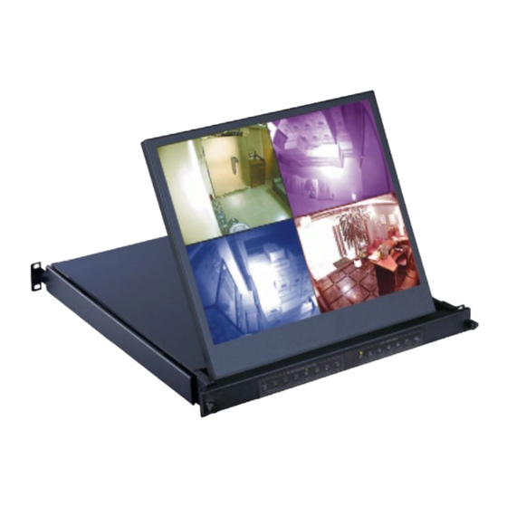
- Page 2 User Manual 19” LCD LCD1U19-0 16 1U Quad Display Drawer Options : - DC power...
- Page 3 Legal Information First English printing, October 2002 Information in this document has been carefully checked for accuracy; however, no guarantee is given to the correctness of the contents. The information in this document is subject to change without notice. We are not liable for any injury or loss that results from the use of this equipment.
-
Page 4: Table Of Contents
Contents Contents < Part. 1 > LCD1U19-016 Package Content Structure Diagram & Dimension P.1 - 2 Installation < Part. 2 > Specifi cations / OSD Product Specifi cations P.4 - 5 On-screen Display Operation ( OSD ) < Part. 3 >... - Page 5 Before Installation ■ It is very important to mount the equipment in a suitable cabinet or on a stable surface. ■ Make sure the place has a good ventilation, is out of direct sunlight, away from sources of excessive dust, dirt, heat, water, moisture and vibration. Unpacking The equipment comes with the standard parts shown in package content.
-
Page 6: Package Content
< Part 1 > < 1.1 > Package Content LCD1U19-016 unit X 1 - 6ft VGA cable X 1 - Power cord X 1 - M6 screw, cage nut & cup washer X 8 The above package content is only for the pure model ( VGA only ). - Page 7 < 1.2 > Dimension Front View UNIT : mm Side View 1mm = 0.03937 inch Top View Product Dimension Model (W x D x H) Weight 442 x 650 x 44 mm 12.5 kg LCD1U19 -016 17.4 x 25.6 x 1.73" 28 lb The weight is only for the pure models.
-
Page 8: Installation
< 1.3 > Installation - How to install Installation Slides Step ■ Insert the left and right rear mounting brackets into the display drawer. Step ■ Measure the depth of the front and rear mounting rails. ■ Align each rear mounting bracket to a suitable length. Step Complete the installation ■... -
Page 9: Product Specifi Cations
< Part 2 > < 2.1 > Product Specifi cations Manufacturer Panel Panel Size ( diagonal ) 19-inch TFT color LCD Display pixel ( dots x lines ) 1280 x 1024 Brightness ( typ. ) Contrast Ratio ( typ. ) 1000:1 Color 16.7 M... - Page 10 Physical Specifi cation Product ( W x D x H ) 442 x 650 x 44 mm 17.4 x 25.6 x 1.73 inch Net Weight 12.5 kgs / 28 lbs VGA Input PC Signal 1280 x 1024 x 60 / 75Hz Applicable Format 1280 x 960 x 60Hz...
-
Page 11: On-Screen Display Operation ( Osd )
< 2.2 > On-screen Display Operation ( OSD ) LCD OSD Menu Power light Green = On Orange = Power saving Membrane Switch Function Power on / off LCD Display the OSD menu Scrolls through menu options and adjusts the displayed control (To auto adjustment by pressing the button for 5 seconds) Exit the OSD screen... -
Page 12: Part. 3 > Options
< Part 3 > < 3.1 > Options : DC Power Model Input rating Input voltage: 12-Volt 24-Volt 48-Volt Input range: 9 ~ 18V 18 ~ 36V 36 ~ 75V Input current - No load 50 mA 50 mA 50 mA - Full load 4950 mA 2450 mA... -
Page 13: Part. 4 > Quad Display Connection & Operation 4.1 Qd Connection
< Part 4 > Quad Display Connection & Operation < 4.1 > QD Connection 1. VCR in : This BNC connector is connected to video output from VCR/DVR. A pre-recorded quad screen signal from a tape can be played back through a VCR/DVR and displayed on the video output channels. Push the VCR button (#2) to switch the device to VCR Playback mode. -
Page 14: Qd Alarm Connection & Operation
< 4.2 > QD ALARM Connection & Operation 1. ALARM I/O : This female type 9 pin D-sub connector is used for alarm sensor input and alarm output control connections. It provides Normal Open and Normal Close contacts for alarm out control. Pin Assignment for Alarm Connector (female type) PIN# PIN#... - Page 15 < 4.2 > QD ALARM Connection & Operation 3 Sensor Activated Alarm The unit is equipped with 4 alarm sensor inputs. If any alarm is activated: ■ the built-in buzzer and the alarm output control relay contact will be activated. ■...
-
Page 16: Qd Remote Control Connection & Operation
< 4.3 > QD Remote Control Connection & Operation Rear Panel h i - z RS-232 1 2 3 4 ALARM monitor dc 12V, 1amp RS-232 Cable Wire Computer Remote Keypad P.11... - Page 17 < 4.3 > QD Remote Control Connection & Operation The device can be controlled via the male type 9 pin D-sub/RS-232 connector to a computer using ASCII code. 1. Pin assignment of the male type 9 pin D-sub connector: Pin Assignment for Remote Control Connector When a computer is used to control this device through a RS-232 port, pin 6, 7, 8, and 9 must be disconnected to prevent connecting the VCC and GND signals from the device to the computer.
- Page 18 < 4.3 > QD Remote Control Connection & Operation *1. In order to control the device to operate in Zoom mode, the computer has to fi rst send command code ” to switch the signal source from camera to VCR/DVR, at this time the device will automatically zoom channel 1 video from VCR/DVR to full screen.
- Page 19 < 4.3 > QD Remote Control Connection & Operation 2.3 The confi guration of the status code for both normal and alarm operations: There are total 2 bytes of the status codes. Byte one, the fi rst 8 bits, shows the current status of the operation modes that the unit is in.
- Page 20 < 4.3 > QD Remote Control Connection & Operation BYTE 2: Status code for alarm operations: The fi rst 4 bits show the sensor activated alarm status of each channel; next 4 bits show the video loss alarm status of each channel. The digit “1” means alarm event is detected, and “0”...
-
Page 21: Qd Osd Operation
< 4.4 > QD OSD Operation Quad Display Control Setup < > Lock: Security locks out button. Push this button for 2 seconds to enable control panel lock out function. Push this button again for 2 seconds to disable the function. VCR: Push this button to enter into VCR Playback/Zoom operation. -
Page 22: Qd On-Screen Menu
< 4.5 > QD On-screen Menu Right after the unit is turned on, The monitor will display the last setting on the Setup Menu. 1. Page 1 of the Setup Menu - Display Setting Push Setup buttons (#1, #2) simultaneously to display the Setup Menu on the screen. There are total two pages in the Setup Menu. - Page 23 < 4.5 > QD On-screen Menu 2 Page 2 of the setup menu- Alarm Setting Push Setup buttons (#1, #2) simultaneously and push (#1) button again to display page 2 of the setup menu on the screen. This Alarm Setting menu is used to set the desired alarm confi guration like sensor type, sensor sensitivity, alarm hold duration, and buzzer.
- Page 24 < 4.5 > QD On-screen Menu 4: The setup menu can be reset to factory setting by pushing the Setup buttons (#1, #2) and power on the quad simultaneously. The factory setting is as follows: ALARM SETTING TITLE DWELL TIME QUAD SENSOR TYPE...
-
Page 25: Qd Vcr Operation
< 4.6 > QD VCR Operation Zoom on VCR playback operation: Push VCR button (#2) to ON will switch the device to VCR playback mode. Under this mode, if the device is on quad display mode, a pr-recorded quad display video in the tape will be shown on the screen. If the device is in Full screen display mode, push any channel select buttons (#5) will select and expand the corresponding quadrants of the pre- recorded video to full screen display. - Page 26 The company reserves the right to modify product specifi cations without prior notice and assumes no responsibility for any error which may appear in this publication. All brand names, logo and registered trademarks are properties of their respective owners. Copyright 2012 Synergy Global Technology Inc. All rights reserved. P.21 www.rackmountmart.com...
Need help?
Do you have a question about the LCD1U19-016 and is the answer not in the manual?
Questions and answers