Advertisement
1150550/6
Waterlogging Sensor Assembly
Installation and Maintenance Instructions
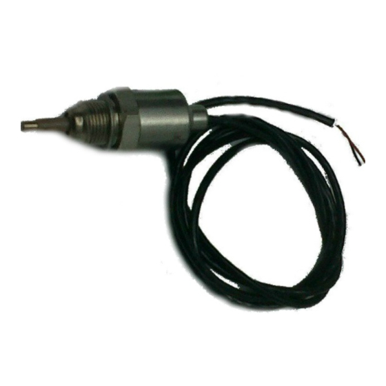
Fig. 1
WLS1 waterlogging
sensor assembly
The WLS1 waterlogging sensor assembly is available in two versions:
1. With a separate diode pack for use with R16C automatic steam trap monitors.
2. Without a diode pack for use with R1C automatic steam trap monitors.
1.
Safety information
Safe operation of these products can only be guaranteed if they are properly installed,
commissioned, used and maintained by qualified personnel (see Section 1.11 on this
document) in compliance with the operating instructions. General installation and
safety instructions for pipeline and plant construction, as well as the proper use of
tools and safety equipment must also be complied with.
1.1
Intended use
Referring to the Installation and Maintenance Instructions, name-plate and Technical
Information Sheet, check that the product is suitable for the intended use /application.
The products comply with the requirements of the European Pressure Equipment
Directive 97 / 23 / EC and fall within category 'SEP'. It should be noted that products
within this category are required by the directive not to carry the
i)
The products have been specifically designed for use on steam and water, which
are in Group 2 of the above mentioned Pressure Equipment Directive. The products'
use on other fluids may be possible but, if this is contemplated, Spirax Sarco should
be contacted to confirm the suitability of the product for the application being
considered.
ii) Check material suitability, pressure and temperature and their maximum and
minimum values. If the maximum operating limits of the product are lower than
those of the system in which it is being fitted, or if malfunction of the product could
result in a dangerous overpressure or overtemperature occurrence, ensure a safety
device is included in the system to prevent such over-limit situations.
iii) Determine the correct installation situation and direction of fluid flow.
iv) Spirax Sarco products are not intended to withstand external stresses that may be
induced by any system to which they are fitted. It is the responsibility of the installer
to consider these stresses and take adequate precautions to minimise them.
v) Remove protection covers from all connections before installation.
IM-P087-34 MI Issue 6
Printed in the UK
Spiratec WLS1
IM-P087-34
MI Issue 6
mark.
© Copyright 2011
1
Advertisement
Table of Contents

Subscribe to Our Youtube Channel
Related Manuals for Spirax Sarco WLS1


Summary of Contents for Spirax Sarco WLS1
- Page 1 Group 2 of the above mentioned Pressure Equipment Directive. The products’ use on other fluids may be possible but, if this is contemplated, Spirax Sarco should be contacted to confirm the suitability of the product for the application being considered.
- Page 2 Allow time for temperature to normalise after isolation to avoid danger of burns. 1.9 Tools and consumables Before starting work ensure that you have suitable tools and/or consumables available. Use only genuine Spirax Sarco replacement parts. 1.10 Protective clothing Consider whether you and/or others in the vicinity require any protective clothing to protect against the hazards of, for example, chemicals, high/low temperature, radiation, noise, falling objects, and dangers to eyes and face.
- Page 3 1.16 Returning products Customers and stockists are reminded that under EC Health, Safety and Environment Law, when returning products to Spirax Sarco they must provide information on any hazards and the precautions to be taken due to contamination residues or mechanical damage which may present a health, safety or environmental risk.
- Page 4 2. Installation Install the WLS1 sensor and cable assembly into the Spiratec sensor chamber or steam trap taking care not to damage the cable. Tighten to a torque of 50 - 56 N m (37 - 42 lbf ft) using a 24 mm A/F spanner.
Need help?
Do you have a question about the WLS1 and is the answer not in the manual?
Questions and answers