Table of Contents
Advertisement
4024750/15
High Integrity, Self-monitoring Low Level Alarm Probe
Installation and Maintenance Instructions
IM-P402-44 AB Issue 15
LP30
1. Safety information
2. General
product information
3. Installation
4. Wiring
5. Probe clearance test
procedure
6. Maintenance
7. Spare parts
IM-P402-44
AB Issue 15
© Copyright 2015
1
Printed in GB
Advertisement
Table of Contents

Related Manuals for Spirax Sarco LP30


Summary of Contents for Spirax Sarco LP30
- Page 1 4024750/15 IM-P402-44 AB Issue 15 LP30 High Integrity, Self-monitoring Low Level Alarm Probe Installation and Maintenance Instructions 1. Safety information 2. General product information 3. Installation 4. Wiring 5. Probe clearance test procedure 6. Maintenance 7. Spare parts © Copyright 2015...
- Page 2 IM-P402-44 AB Issue 15...
-
Page 3: Safety Information
Installation and Maintenance Instructions, could cause damage to the product and may cause injury or fatality to personnel. The LP30 level probe and LC3050 level controller comply with the requirements of the European Pressure Equipment Directive 97 / 23 / EC and carry the mark. -
Page 4: Pressure Systems
1.9 Tools and consumables Before starting work ensure that you have suitable tools and / or consumables available. Use only genuine Spirax Sarco replacement parts. 1.10 Protective clothing Consider whether you and / or others in the vicinity require any protective clothing to protect against the hazards of, for example, chemicals, high / low temperature, radiation, noise, falling objects, and dangers to eyes and face. -
Page 5: Returning Products
1.17 Returning products Customers and stockists are reminded that under EC Health, Safety and Environment Law, when returning products to Spirax Sarco they must provide information on any hazards and the precautions to be taken due to contamination residues or mechanical damage which may present a health, safety or environmental risk. -
Page 6: General Product Information
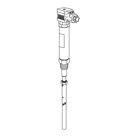
2. General product information 2.1 General description The Spirax Sarco LP30 level probe is used with the Spirax Sarco LC3050 level controller to provide a high integrity, self-monitoring low level alarm signal, usually in a steam boiler. It consists of a probe body with a removable cable socket, and a separate screw-on probe tip. - Page 7 4 off 18 AWG flying leads 300 mm (12") long Probe body 27 A / F ½" BSP ½" NPT taper connection taper connection Comparator tip Probe tip Fig. 2 Fig. 1 LP30 Standard version LP30 UL version IM-P402-44 AB Issue 15...
-
Page 8: Installation
3. Installation Before proceeding with any installation or maintenance read Section 1, 'Safety information'. When the probe is to be installed in the boiler, ensure it is positioned at least 1 metre (39") from any safety valve or steam take-off, as increased localised water levels may occur. 3.1 Deciding on the low alarm levels In most shell boilers the water will 'swell' when it is firing, such that the actual water level will be higher than the level shown in the gauge glass. - Page 9 Boiler shell 20 mm (¾") vent hole as high as possible Minimum Ø 80 mm 20 mm (¾") Fig. 4 Typical protection tube IM-P402-44 AB Issue 15...
- Page 10 - Mark a line down the length of the probe tip using a water-soluble felt pen. - Temporarily fit the probe and tip to the boiler (½" BSP taper for standard LP30 and ½" NPT for UL / FM versions), hand tight, without using PTFE tape.
- Page 11 15 mm (½") Probe body approximately 6 mm flat Lock-nut Retaining pin at bottom of slot Dipped length Probe tip Fig. 5 Fig. 6 3.3.2 Install the probe as follows: - Ensure both male and female threads are in good condition. - Use up to three turns (no more) of PTFE thread sealing tape on the probe thread.
- Page 12 The flexible conduit and terminal box are not to incorporate any other control wiring as this may damage or reduce the performance of the product. It is not possible to rotate the cable socket in 90° steps, as with the non-listed LP30. To do so may damage the internal wiring.
- Page 13 LC3000 controller Screen LP30 connector Ensure that resistance from the probe body to boiler shell is less than 1 . * Internal resistor Internal link Comparator tip Low alarm tip Fig. 8 Standard version LC3000 controller Screen Terminal box LP30 connector...
- Page 14 LC3050 controller Screen LP30 connector Ensure that resistance from the probe body to boiler shell is less than 1 . * Internal resistor Internal link Comparator tip Low alarm tip Fig. 10 Standard version IM-P402-44 AB Issue 15...
- Page 15 LC3050 controller Screen Terminal box LP30 connector Ensure that resistance from the probe body to boiler shell is less than 1 . * Internal resistor Internal link Comparator tip Low alarm tip Fig. 11 UL / FM version IM-P402-44 AB Issue 15...
- Page 16 14 mm ( ") clearance. This test confirms that the LP30 probe is installed correctly. The test must be done on initial installation, and each time the probe is removed from the boiler, e.g. for annual inspection. A pair of 'checking wires' are used in conjunction with an Insulation Resistance Tester (meter) to test if there is less than 14 mm ( ") radial clearance from the tip end.
-
Page 17: Test Method
5.2 Test method 1. Drain water level to at least 50 mm (2") below alarm level and vent boiler or vessel to atmosphere. 2. Remove probe (if installed) and fit a pair of checking wires to the end of the probe tip, 90° relative to each other and a maximum 10 mm ( ") from the tip end - see Figures 13 and 14. - Page 18 5.3 Probe clearance record sheet We strongly recommend that a record of the probe clearance test is kept, and a sheet is provided for this purpose. This must be completed each time the probe is fitted /refitted. How to complete the sheet: - Date: The date the test procedure was carried out.
- Page 19 - WARNING: It is essential to remove the checking wires from the probe before commissioning the boiler or vessel. Failure to do this could stop the low water alarms operating. - The person who removes the checking wires must sign the record sheet to verify that this has been completed.
-
Page 20: Maintenance
Always order spares by using the description given in the column headed 'Available spares' and state for which product they are required. Example: 1 off Spring clearance checking set for a Spirax Sarco LP30 high integrity, self-monitoring low level alarm probe.
Need help?
Do you have a question about the LP30 and is the answer not in the manual?
Questions and answers