Table of Contents
Advertisement
Quick Links
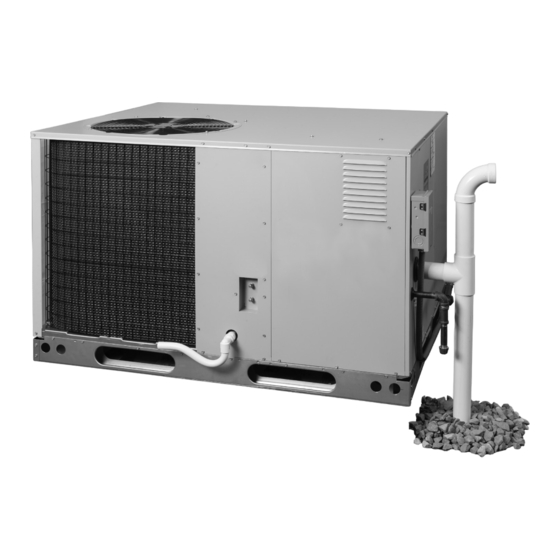
R104HD SERIES
INSTALLATION INSTRUCTIONS
SINGLE PACKAGE GAS HEATING / ELECTRIC COOLING
SINGLE PHASE
HORIZONTAL MOUNT SHOWN
WARNING
FIRE OR EXPLOSION HAZARD
Failure to follow safety warnings exactly could
result in serious injury or property damage.
– Do not store or use gasoline or other flammable
vapors and liquids in the vicinity of this or any
other appliance.
WHAT TO DO IF YOU SMELL GAS
• Do not try to light any appliance.
• Do not touch any electrical switch; do not use
any phone in your building.
• Leave the building immediately.
• Immediately call your gas supplier from a
neighbors phone. Follow the gas suppliers
instructions.
• If you cannot reach your gas supplier, call the
fire department.
– Installation and service must be performed by
a qualified installer, service agency or the gas
supplier.
DO NOT DESTROY THIS MANUAL. READ ALL INSTRUCTIONS IN THIS MANUAL AND KEEP IN A SAFE PLACE FOR FUTURE REFERENCE.
NE PAS DÉTRUIRE. LIRE TOUTES LES INSTRUCTIONS DONNÉE DANS LE MANUEL ET CONSERVER EN UN LIEU SÛR POUR RÉFÉRENCE ULTÉRIEURE.
AVERTISSEMENT
RISQUE D'INCENDIE OU D'EXPLOSION
Si les consignes de sécurité ne sont pas suivies à la
lettre, cela peut entraîner la mort, de graves blessures
ou des dommages matériels.
– Ne pas entreposer ni utiliser de l'essence ni d'autres
vapeurs ou liquides inflammables dans le voisinage
de cet appareil, ni de tout autre appareil.
QUE FAIRE SI UNE ODEUR DE GAZ EST
DÉTECTÉE
• Ne mettre en marche aucun appareil.
• Ne toucher aucun interrupteur électrique; ne pas
utiliser de téléphone dans le bâtiment.
• Quitter le bâtiment immédiatement.
• Appeler immédiatement le fournisseur de gaz
en utilisant le téléphone d'un voisin. Suivre les
instructions du fournisseur de gaz.
• Si le fournisseur de gaz n'est pas accessible, appeler
le service d'incendie.
– L'installation et l'entretien doivent être effectués
par un installateur ou une entreprise d'entretien
qualifié, ou le fournisseur de gaz.
13.4 SEER2 / 95% AFUE
Advertisement
Table of Contents

Related Manuals for Nortek R104HD Series


Summary of Contents for Nortek R104HD Series
- Page 1 R104HD SERIES 13.4 SEER2 / 95% AFUE INSTALLATION INSTRUCTIONS SINGLE PACKAGE GAS HEATING / ELECTRIC COOLING SINGLE PHASE HORIZONTAL MOUNT SHOWN WARNING AVERTISSEMENT FIRE OR EXPLOSION HAZARD RISQUE D’INCENDIE OU D’EXPLOSION Failure to follow safety warnings exactly could Si les consignes de sécurité ne sont pas suivies à la lettre, cela peut entraîner la mort, de graves blessures...
-
Page 2: Table Of Contents
TABLE OF CONTENTS IMPORTANT SAFETY INFORMATION ......3 COMPONENT FUNCTIONS ..........23 REQUIREMENTS & CODES ..........4 EQUIPMENT MAINTENANCE ..........24 Heat Exchanger & Burner Maintenance ........24 GENERAL INFORMATION ..........5 Cleaning of Burners ..............25 Before you install this unit ............5 REPLACEMENT PARTS ............ -
Page 3: Important Safety Information
IMPORTANT SAFETY INFORMATION WARNING: Please read all instructions before servicing this equipment. Pay attention to all safety warnings and any other special PROPOSITION 65 WARNING: This product notes highlighted in the manual. Safety markings are contains fiberglass insulation. Disturbing the used frequently throughout this manual to designate a insulation of this product during installation, degree or level of seriousness and should not be ignored. -
Page 4: Requirements & Codes
• The installer should become familiar with the units wiring • Use only with the type of gas approved for this unit. diagram before making any electrical connections to the Refer to the unit rating plate. unit. See the unit wiring label or Figure 13 (page 37). -
Page 5: General Information
Locating the Equipment GENERAL INFORMATION • Select a solid, level position, preferably on a concrete This Single Package Gas Heating / Electric Cooling slab, slightly above the grade level, and parallel to the Unit is designed for outdoor rooftop or ground level home. -
Page 6: Combustion Air & Venting Requirements
COMBUSTION AIR & VENTING REQUIREMENTS WARNING: AVERTISSEMENT: CARBON MONOXIDE POISONING HAZARD RISQUE D’INTOXICATION AU MONOXYDE DE CARBONE Failure to follow the steps outlined below for each appliance connected to the venting Si les étapes décrites ci-dessous ne sont pas suivies pour chacun des appareils raccordés au system being placed into operation could système de ventilation au moment de sa mise result in carbon monoxide poisoning or death. -
Page 7: Vent Termination
WARNING: WARNING: Installation methods other than those described This unit is intended for outdoor installation in the following sections must comply with the only. This unit must be vented to the outdoors. National Fuel Gas Code and all applicable local No additional venting shall be used. -
Page 8: Circulating Air Supply
• The vent termination must be located at least 3 feet • Design the duct work according to Manual D by the Air above any forced air inlet located within 10 feet. Conditioning Contractors of America (ACCA). • The vent termination must be located at least 4 feet •... -
Page 9: Unit Installation
UNIT INSTALLATION attachment flanges by bending the sheet metal outward 90 degrees along the perforated lines. Packaging Removal • Firmly attach ductwork directly to these flanges with Remove the shipping carton and User’s Manual from the screws or other approved mechanical connections and equipment. -
Page 10: Horizontal To Downflow Conversion
IMPORTANT NOTES TO INSTALLER • All panels must be securely in place during rigging and • When setting the roof curb for installation, routing and hoisting, except control access panel. See page 47 securement of the gas heat exchanger condensate for additional lifting and setting of unit requirements. -
Page 11: Air Filter Requirements
• Single phase downflow applications require either a NOTE TO INSTALLER: After installing or replacing the Nortek internal filter kit be used or an air filter system filtration system for this unit, add the following statement be installed in the return air ductwork. See Table 1 on or adjacent to the filter service panel: “Replace... -
Page 12: Electrical Wiring
Pre-Electrical Checklist ELECTRICAL WIRING (Single Phase Models) WARNING: √ Verify the voltage, frequency, and phase of the supply source match the specifications on the unit rating plate. √ Verify that the service provided by the utility is sufficient ELECTRICAL SHOCK, FIRE OR to handle the additional load imposed by this equipment. -
Page 13: Thermostat / Low Voltage Connections
• Add the current draw of the system heating components. Thermostat / Low Voltage Connections • This unit is designed to operate from a 24 VAC Class II • Measure the current flow on the thermostat R-W circuit control circuit. A single stage cooling / two stage heating after the circulating blower motor has started. -
Page 14: Configuring The Fixed Speed Blower
Configuring the Fixed Speed Blower when there is a call for cooling. There are many ways this The fixed speed blower assembly has been designed to function can be electrically wired. give the installer maximum flexibility for optimizing system When 24VAC is present at the DEHUM terminal of the performance, efficiency, and comfort. -
Page 15: Gas Supply & Piping
GAS SUPPLY & PIPING additional requirements regarding placement of the manual main gas shut-off. See Figure 6 (page WARNING: 16). • The manifold pressure must be set to the appropriate value for your installation. To measure and adjust FIRE OR EXPLOSION HAZARD the manifold pressure see page •... -
Page 16: High Altitude Conversion - Natural Gas
For altitudes between 2,000 and 10,000 feet above sea Shut-Off Valve level, the unit can be converted by adjusting the unit’s with 1 /8 NPT Automatic Gas Valve plugged tap manifold pressure and/or changing the orifices. See Table (with manual shut-off) for the correct manifold pressure settings. -
Page 17: Start Up & Adjustments
START UP & ADJUSTMENTS NOTE: When FAN ON is selected, the blower will operate at 50% of selected airflow when no call for heating or Pre-Start Check List cooling is present. √ Verify the unit is level and allows evaporator condensate to drain. -
Page 18: Verifying System Heating
5. Set the thermostat above room temperature to begin increases the temperature rise and a higher speed the heating cycle of the furnace. decreases the temperature rise. 6. Check that the furnace ignites and operates properly. The unit is equipped with an ECM type motors. Speed 7. -
Page 19: Measuring The Manifold Pressure
Adjusting the Manifold Pressure EXAMPLE NOTE: If adjustment must be made to either LOW or (INPUT --> HIGH = 100,000 / LOW = 65,000) HIGH fire settings perform the following steps: • Time for 1 revolution of a gas meter with a 1 cubic foot dial 1. - Page 20 -X24K060C 10.0 60,000 57,000 39,000 37,050 30-60 0.80 24,000 11” x 8” -X30K060C 10.0 60,000 57,000 39,000 37,050 30-60 0.80 28,600 11” x 8” -X36K080C 10.0 80,000 76,000 52,000 49,400 35-65 0.80 34,600 11” x 8” -X42K080C 10.0 80,000 76,000 52,000 49,400 35-65...
-
Page 21: Verifying System Cooling
2. Set thermostat above room temperature and observe depression device present to actuate the valve. Draw a the ignition sequence. vacuum on gauge lines to remove air before attaching them to the service ports on the unit. Refrigerant charging NOTE: The burner flame should carry over immediately must be done by qualified personnel familiar with safe between all burners without lifting off, curling, or floating. -
Page 22: Operating Sequence
OPERATING SEQUENCE 7. Flame Proving / Ignition / Low Heat Operation - The furnace control must prove flame via the flame sensor The operating sequences for the heating, cooling, and 5 seconds after the high main gas valve is energized. fan modes are described below. -
Page 23: Thaw Cycle Start Up / Shutdown
De-Humidification Control NOTE: This unit has two special features programmed into the furnace control board for If installing a humidistat, install it in the return air duct as directed in the installation instructions included in the safety and proper unit operation. accessory kit. -
Page 24: Equipment Maintenance
EQUIPMENT MAINTENANCE CAUTION: WARNING: The unit should never be operated without a filter in the return air system. Replace disposable ELECTRICAL SHOCK, FIRE OR filters with the same type and size. EXPLOSION HAZARD Failure to follow safety warnings exactly could •... -
Page 25: Cleaning Of Burners
Pressure Switch Open Fault Flash Open Limit Switch Fault Flash Replacement parts are available through all Nortek distributors. Please have the complete model and serial Motor Fault number of the unit when ordering replacement parts. Blocked Condensate Drain or Vent... -
Page 26: Figures & Tables
FIGURES & TABLES INSIDE PERIMETER 3/4" NPT OF BASE RAIL FEMALE DRAIN (IF USED) CONNECTOR 2.63 DOWNFLOW SUPPLY DUCT TOP VIEW OPENING (Horizontal Application Shown) 47.50 45.75 13.50 13.50 13.31 23.50 DOWNFLOW RETURN DUCT OPENING 1.75 HORIZONTAL HORIZONTAL RETURN DUCT SUPPLY DUCT OPENING OPENING... - Page 27 7.03 6.53 5.40 ELECTRIC SUPPLY 2.03 ENTRY (1.25” DIA.) LOW VOLTAGE ENTRY (0.875” DIA.) SIDE VIEW BLOWER ACCESS VENT ASSEMBLY (DOWNFLOW APPLICATION) 25.65 25.15 GAS SUPPLY ENTRY 14.82 (1.625” DIA) 2.03 47.50 5.40 2.03 ELECTRIC SUPPLY ENTRY (1.25” DIA.) CONDENSATE DRAIN AND LOW VOLTAGE VENT ASSEMBLY...
-
Page 28: Airflow Information
Airflow Information 2 & 2.5 TON 3.5 TON SWITCH SWITCH RECOMMENDED RECOMMENDED SETTING SETTING AIRFLOW (CFM) AIRFLOW (CFM) SWITCH SWITCH HIGH HIGH 5 6 7 8 5 6 7 8 SETTING SETTING HEAT HEAT HEAT HEAT 0 0 0 0 0 0 0 0 39,000 60,000... - Page 29 R104HD -X24K060C / -X30K060C 60,000 BTUH, 30” CABINET, 11”X8” BLOWER W- 3/4 HP ECM MOTOR 230 VOLT OPERATION SWITCH 0.20 0.30 0.40 0.50 0.60 0.70 0.80 0.90 1.00 SETTINGS CFM RISE CFM RISE CFM RISE CFM RISE CFM RISE CFM RISE CFM RISE CFM RISE CFM RISE 1039 1113 1073...
- Page 30 R104HD -X36K080C 80,000 BTUH, 30” CABINET, 11”X8” BLOWER W- 1 HP ECM MOTOR 230 VOLT OPERATION SWITCH 0.20 0.30 0.40 0.50 0.60 0.70 0.80 0.90 1.00 SETTINGS CFM RISE CFM RISE CFM RISE CFM RISE CFM RISE CFM RISE CFM RISE CFM RISE CFM RISE 1272 1227 1181...
- Page 31 R104HD -X42K080C 80,000 BTUH, 34” CABINET, 11”X10” BLOWER W- 1 HP ECM MOTOR 230 VOLT OPERATION SWITCH 0.20 0.30 0.40 0.50 0.60 0.70 0.80 0.90 1.00 SETTINGS CFM RISE CFM RISE CFM RISE CFM RISE CFM RISE CFM RISE CFM RISE CFM RISE CFM RISE 1347 1295 1242...
- Page 32 R104HD -X48K096C & R104HD -X60K096C 96,000 BTUH, 38”-42” CABINET, 11”X10” BLOWER W- 1 HP ECM MOTOR 230 VOLT OPERATION SWITCH 0.20 0.30 0.40 0.50 0.60 0.70 0.80 0.90 1.00 SETTINGS CFM RISE CFM RISE CFM RISE CFM RISE CFM RISE CFM RISE CFM RISE CFM RISE CFM RISE 1347 1295 1242...
-
Page 33: Gas Information
Gas Information CAPACITY OF BLACK IRON GAS PIPE (CU. FT. PER HOUR) FOR NATURAL GAS (SPECIFIC GRAVITY - 0.60) LENGTH OF PIPE RUN (FEET) NOMINAL PIPE DIAMETER (IN.) 1 1/4 1,050 1 1/2 1,600 1,100 Input To Furnace (Btu/hr) Cubic Feet Per Hour Required = Heating Value of Gas (Btu/Cu. - Page 34 FOR YOUR SAFETY READ POUR VOTRE SÉCURITÉ. BEFORE OPERATING À LIRE AVANT L’EMPLOI ATTENTION! L’inobservation de ces instructions WARNING: If you do not follow these instructions peut entraîner un incendie ou une explosion pouvant exactly, a fi re or explosion may result causing property causer des dam mages à...
-
Page 35: Electrical Data
Electrical Data SINGLE PHASE MODELS MAXIMUM INDUCER VOLTAGE MODEL HEATING NOMINAL BLOWER MINIMUM COMPRESSOR OVER- MOTOR RANGE NUMBER INPUT ELECTRICAL MOTOR CIRCUIT AMPS CURRENT R104HD (BTUH) SUPPLY AMPS AMPACITY MIN. MAX. PROTECTION High - 60,000 X24K060C 0.30 208/230-1-60 12.8 22.4 Low - 39,000 High - 60,000 X30K060C... -
Page 36: Electrical Diagrams
Electrical Diagrams THERMOSTAT TERMINAL STRIP Blower (Auto or Continuous ON) GREEN BLACK (Optional) 24VAC (Common) NOT USED WHITE Stage Heat 24VAC NOT USED NOT USED NOT USED YELLOW Stage Cool BROWN Stage Heat To Blower Control Board (Optional) DEHUM Figure 10. Two Stage Heating / Single Stage Cooling Configuration TEST PORT EXPANSION PORT... -
Page 37: Wiring Diagrams
Wiring Diagrams LINE- N LINE- N XMFR-N LINE LINE XMFR Figure 13. Single Phase, 2-5 Ton, 208/230V... -
Page 38: Charging Charts
Charging Charts 2 TON CHARGING CHART Remove refrigerant when above curve Add refrigerant when below curve Liquid Temperature (F) Figure 14. Charging Chart for 2 Ton Units 2.5 TON CHARGING CHART Remove refrigerant when above curve Add refrigerant when below curve Liquid Temperature (F) Figure 15. - Page 39 3 TON CHARGING CHART Remove refrigerant when above curve Add refrigerant when below curve 115 120 Liquid Temperature (F) Figure 16. Charging Chart for 3 Ton Units 3.5 TON CHARGING CHART Remove refrigerant when above curve Add refrigerant when below curve Liquid Temperature (F) Figure 17.
- Page 40 4 TON CHARGING CHART Remove refrigerant when above curve Add refrigerant when below curve Liquid Temperature (F) Figure 18. Charging Chart for 4 Ton Units 5 TON CHARGING CHART Remove refrigerant when above curve Add refrigerant when below curve 125 130 Liquid Temperature (F) Figure 19.
-
Page 41: Internal Filter Conversion
Internal Filter Conversion 1 Inch Filter Installations 2 Inch Filter Installations Figure 20. Filter Comversion... -
Page 42: Appendix A - Heat Exchanger Condensate Drain & Vent Kit (Horizontal Mount Applications)
R8HE/R104HD series condensing style package gas/ when disposing directly into the ground. Check state electric units. These instructions may be used to properly... -
Page 43: Preparing The Pit
Vertical Drain Pipe Installation NOTE TO INSTALLER 1. After the pit has been dug out, pour the rock or chat READ THIS BEFORE YOU DIG! base to a level approximately 2” below the frost line. Mix in 50% of the limestone rock, chat, or lime pellets Before you begin digging the pit for the condensate (if required by code) with the initial rock base. -
Page 44: Preparing The Trench
on the final depth of the trench if the frost line cannot be 10. Work the drain hose assembly into the pipe until the reached. The unit will operate longer and more frequently entire length is inside and the PVC pipe is vertical. during colder weather to help keep the trench from freezing. - Page 45 SLAB MOUNT FLUE GAS AND CONDENSATE DISPOSAL USING A VERTICAL DRAIN PIT GRADE LEVEL GRADE LEVEL BACK FILL FROST LINE ROCK/DIRT MIXTURE ROCK BASE Figure 21. Condensate Disposal Using A Vertical Drainage Pit SLAB MOUNT FLUE GAS AND CONDENSATE DISPOSAL USING A HORIZONTAL DRAIN TRENCH GRADE LEVEL...
-
Page 46: Appendix B - Heat Exchanger Condensate Drain & Vent Kit (Roof Curb Mount Applications)
• Nortek Condensate Drain & Vent Kit # 922485 is set Securement of the drain line to the inside surface of up for installing the HX condensate drain line straight the roof curb is acceptable and should be made in the down through the roof. -
Page 47: Setting The Unit
• The condensate drain line must be trapped using a kit routing the condensate drain line up through (Nortek P/N- 922485) or field supplied parts. After the the bottom of the unit. After enough drain line drain trap, condensate can continue to the drain by is passed through the bottom pan opening to connecting to a recommended 3/4”... - Page 48 ROOF MOUNTED UNIT (ROOF CURB AND ROOF NOT SHOWN) Condensate Drain Valve (”D” Position for Downflow Applications Only) 2” PVC x 22.5 Degree Elbow & 1/4” Mesh Screen Spring Hose Clamp Flexible Insulation (Optional) To building drain per J-Trap State and Local Codes Height 1/2”...
-
Page 52: Installation Checklist
Some local codes require licensed installation/service personnel for this type of equipment. Single Phase Models Only Specifications & illustrations subject to change without notice or incurring obligations (06/22). O’Fallon, MO, © Nortek Global HVAC LLC 2022. All Rights Reserved. 10408430 (NEW)
Need help?
Do you have a question about the R104HD Series and is the answer not in the manual?
Questions and answers