Table of Contents
Advertisement
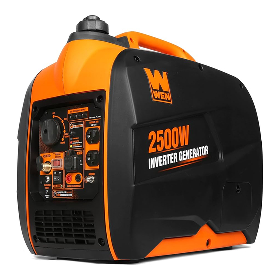
MODEL DF250iX
2500W DUAL FUEL
INVERTER GENERATOR
Instruction Manual
NEED HELP? CONTACT US!
Have product questions? Need technical support? Please feel free to contact us:
1-800-232-1195 (M-F 8AM-5PM CST)
TECHSUPPORT@WENPRODUCTS.COM
IMPORTANT: Your new tool has been engineered and manufactured to WEN's highest standards for dependability,
ease of operation, and operator safety. When properly cared for, this product will supply you years of rugged,
trouble-free performance. Pay close attention to the rules for safe operation, warnings, and cautions. If you use
your tool properly and for its intended purpose, you will enjoy years of safe, reliable service.
WENPRODUCTS.COM
For replacement parts and the most up-to-date instruction manuals, visit
Advertisement
Table of Contents

Subscribe to Our Youtube Channel
Related Manuals for Wen DF250iX


Summary of Contents for Wen DF250iX
- Page 1 1-800-232-1195 (M-F 8AM-5PM CST) TECHSUPPORT@WENPRODUCTS.COM IMPORTANT: Your new tool has been engineered and manufactured to WEN’s highest standards for dependability, ease of operation, and operator safety. When properly cared for, this product will supply you years of rugged, trouble-free performance. Pay close attention to the rules for safe operation, warnings, and cautions. If you use your tool properly and for its intended purpose, you will enjoy years of safe, reliable service.
-
Page 2: Table Of Contents
CONTENTS WELCOME Specifications ....................3 Introduction ..................... 4 SAFETY Safety Information ................... 5 Generator Safety Warnings ................6 BEFORE OPERATING Unpacking & Packing List ................9 Know Your Inverter Generator ................ 10 Generator Preparation ..................12 OPERATION & MAINTENANCE Starting Your Generator ................. 18 Using Your Generator .................. -
Page 3: Welcome
SPECIFICATIONS GENERATOR Rated Wattage Gasoline: 2000 Watts; LPG: 1800 Watts Surge Wattage Gasoline: 2500 Watts; LPG: 2250 Watts AC: 120V Rated Voltage DC: 5V AC: 16.6A (Gasoline), 15A (LPG) Rated Amperage DC: 1A (Top), 2.1A (Bottom) Phase Single Frequency 60 Hz Decibel Rating 52 dBA (No Load) Length: 19 Inches... -
Page 4: Introduction
INTRODUCTION Thanks for purchasing the WEN 2500-Watt Dual-Fuel Inverter Generator. Refer to the illustration below for the loca- tion of the serial number on the side of the engine. Record the generator information in the spaces provided below. If assistance for information or service is required, please contact customer service by calling 1-800-232-1195, M-F 8-5 CST;... -
Page 5: Safety
WEN reserves the right to change this product and specifications at any time without prior notice. At WEN, we are continuously improving our products. If you find that your tool does not exactly match this manual, please visit wenproducts.com for the most up-to-date manual or contact customer service at 1-800-232-1195, M-F 8-5 CST. -
Page 6: Generator Safety Warnings
GENERATOR SAFETY WARNINGS DANGER! CARBON MONOXIDE Using a generator indoors CAN KILL YOU IN MINUTES. Generator exhaust contains carbon monoxide (CO). This is a poison gas you cannot see or smell. If you can smell the generator exhaust, you are breathing CO. But even if you cannot smell the exhaust, you could be breathing CO. - Page 7 GENERATOR SAFETY WARNINGS WARNING! Do not let comfort or familiarity with the product replace strict adherence to product safety rules. Failure to follow the safety instructions may result in serious personal injury. OPERATING ENVIRONMENT 3. If any part of the generator, electrical device or pow- er cord is broken, damaged, or defective, make sure 1.
- Page 8 GENERATOR SAFETY WARNINGS WARNING! Do not let comfort or familiarity with the product replace strict adherence to product safety rules. Failure to follow the safety instructions may result in serious personal injury. TO MAXIMIZE THE LIFESPAN OF YOUR GENERATOR: We recommend running your generator at least once a month for 20 to 30 minutes.
-
Page 9: Before Operating
UNPACKING & PACKING LIST UNPACKING With the help of a friend or trustworthy foe, such as one of your in-laws, carefully remove the generator from the packaging and place it on a sturdy, flat surface. Make sure to take out all contents and accessories. Do not discard the packaging until everything is removed. -
Page 10: Know Your Inverter Generator
KNOW YOUR INVERTER GENERATOR TOOL PURPOSE Inverter Generators provide you with clean and quiet power, when and where you need it most. Refer to the fol- lowing diagrams to become familiarized with all the parts and controls of your Generator. The components will be referred to later in the manual for assembly and operation instructions. - Page 11 KNOW YOUR INVERTER GENERATOR CONTROL PANEL 1. 3-In-1 Dial Switch 6. DC 5V USB Port Off, Run, Half-Choke, Choke. 1A & 2.1A for charging various electronic devices. 2. Indication Lights 7. Parallel Connection Low Oil (Yellow), Overload (Red), & Output (Green). Connect to share wattage between inverter generators 3.
-
Page 12: Generator Preparation
GENERATOR PREPARATION The following section describes the necessary steps to prepare the generator for use. If you are unsure about how to perform any of the steps please call 1-(800) 232-1195 M-F 8-5 CST for customer service. Failure to perform these steps properly can damage the generator or shorten its life. - Page 13 Indicator TIP: Your WEN generator is compatible with the WEN 55201 Magnetic Oil Dipstick (not included), available for purchase at wenproducts.com. The dipstick’s industrial-strength magnetic tip will collect metal shavings from your generator’s oil tank to help preserve the engine and extend your generator’s lifespan.
- Page 14 GENERATOR PREPARATION STEP 2 - ADD / CHECK FUEL FUEL OPTION A: GASOLINE WARNING! RISK OF EXPLOSION. HIGHLY FLAMMABLE: This generator may emit highly flammable and explosive gasoline vapors, which can cause severe burns or even death, if ignited. A nearby open flame can lead to explosion even if not directly in contact with gasoline.
- Page 15 If bubbles appear, become larger in size, or increase in number, a leak exists. This MUST be corrected before using generator. Contact WEN customer service at 1-800-232- 1195, M-F 8-5 CST, or email techsupport@wenproducts.com for as- sistance.
- Page 16 GENERATOR PREPARATION AUTO FUEL SELECTION Your generator is equipped with Auto Fuel Selection Technology. What this means is that the generator will auto- matically select the fuel source (LPG or gasoline) depending on availability. LPG is prioritized; this means that if a propane tank with enough LPG is connected, the generator will automatically use LPG.
- Page 17 GENERATOR PREPARATION STEP 3 - GROUND THE GENERATOR Fig. 10 To reduce the risk of electric shock and to maximize safety, the genera- tor should be properly grounded. Ground the generator by tightening the grounding nut on the front con- trol panel (Fig.
-
Page 18: Operation & Maintenance
STARTING YOUR GENERATOR Before starting the generator, make sure you have read and performed the steps in the “Generator Preparation” section of this manual. If you are unsure about how to perform any of the steps in this manual please call 1-(800) 232-1195 M-F 8-5 CST for customer service. - Page 19 STARTING YOUR GENERATOR Before starting the generator, check the following: Fig. 11 1. Place the generator outside on a dry, level surface. Allow at least two feet of clearance on all sides of the generator. 2. Make sure all electrical devices are unplugged from the generator during ignition.
- Page 20 STARTING YOUR GENERATOR When starting your generator in low temperatures (below 32º F): Fig A 1. Turn the 3-in-1 switch to the "Choke" position (Fig. A). 2. Use the recoil starter handle to start the generator (Fig. B). 3. Turn the 3-in-1 switch to the "Half Choke" position for about 15 sec- onds.
-
Page 21: Using Your Generator
USING YOUR GENERATOR CALCULATING THE WATTAGE OF YOUR DEVICE(S) Connect electrical devices running on AC current according to their wattage requirements. Calculate the total run- ning wattage and starting wattage of the device(s) you wish to connect, and MAKE SURE that they are within the capacity of your generator and the capacity of each individual outlet. - Page 22 USING YOUR GENERATOR CALCULATING THE WATTAGE OF YOUR DEVICE(S) - CONTINUED The chart below serves as a reference for the estimated wattage requirements of common electrical devices. How- ever, do not solely rely on this chart - all electronics and appliances are built differently. Always check the wattage listed on the electrical device before consulting this chart.
- Page 23 USING YOUR GENERATOR CONNECTING ELECTRICAL DEVICES When the rated wattage requirement of each electrical device has been determined, add these numbers to find the total rated wattage needed. If this number exceeds the rated wattage (2000W gasoline, 1800W LPG) of the genera- tor, DO NOT connect all these devices.
- Page 24 1500W / 1350W. PARALLEL OPERATION The parallel connection ports allow you to connect two WEN generators to increase the total available electrical power. The WEN Parallel Connection Kit can be purchased from wenproducts.com. Follow the instructions in- cluded with your parallel connection kit for proper installation and operation.
- Page 25 USING YOUR GENERATOR SOME NOTES ABOUT POWER CORDS Long or thin cords can drain the power provided to an electrical device by the generator. When using such cords, allow for a slightly higher rated wattage requirement by the electrical device. Device Requirements Max.
- Page 26 • The CO sensor has a lifetime of about 7 years, and is capable of monitoring its lifetime. If your generator shows an error light several years after purchase, it may be time to replace the CO sensor. Contact WEN customer service...
-
Page 27: Shutting Off Your Generator
OPTION 1A: AUTOMATIC FUEL SHUTOFF (RECOMMENDED – GASOLINE ONLY) The WEN 2500W Inverter Generator is equipped with automatic fuel shutoff. This feature turns off the flow of fuel, allowing for the generator to use up the remaining fuel from the carburetor before turning off. This prolongs the lifespan of the generator by preventing build-up and blockages caused by stagnant fuel inside of a carburetor. - Page 28 SHUTTING OFF THE GENERATOR CAUTION! Unplugging running devices can cause damage to the generator. Never stop the engine with elec- trical devices connected and running. OPTION 2: MANUAL SHUTOFF In case you are in a hurry and do not want to wait for the generator to automatically shut down, the manual shutoff feature is available.
-
Page 29: Maintenance
MAINTENANCE Proper routine maintenance of the generator will help prolong the life of the machine. Please perform maintenance checks and operations according to the schedule in Table 4. CAUTION! Never perform maintenance operations while the generator is running. Before maintaining or servicing the generator, turn OFF the generator, disconnect all devices and allow the generator to cool down. - Page 30 TIP: Your WEN generator is compatible with the WEN 55201 Magnetic Oil Dipstick (not included), available for purchase at wenproducts.com. The dipstick’s industrial-strength magnetic tip will collect metal shavings from your generator’s oil tank to help preserve the engine and extend your generator’s lifespan.
- Page 31 MAINTENANCE DRAINING THE CARBURETOR We recommended draining the carburetor after every use (not necessary if the generator is shut off using the “FUEL OFF” option), and before storing the generator. Draining the carburetor can prevent the fuel from clogging up the carburetor and preventing the generator from starting. 1.
- Page 32 MAINTENANCE AIR FILTER MAINTENANCE Check every 50 hours of operation (refer to Table 4 - Recommended Maintenance Schedule). Routine maintenance of the air filter helps maintain proper airflow to the carburetor. Occasionally check that the air cleaner is free of excessive dirt. To inspect and clean the air filter: Fig.
- Page 33 MAINTENANCE DRAINING/CHANGING OIL Change the oil according to the Recommended Maintenance Schedule in Table 4. Change the oil MORE OFTEN if operating under heavy load or high ambient temperatures. It is also necessary to drain the oil from the crankcase if it has become contaminated with water or dirt. Changing the oil when the engine is warm allows for complete drainage.
- Page 34 MAINTENANCE SPARK PLUG MAINTENANCE Refer to Recommended Maintenance Schedule in Table 4 for maintaining the spark plug. The spark plug is important for proper engine operation. Check the spark plug regularly to maintain proper engine operation. A good spark plug should be intact, free of deposits, and properly gapped. To inspect or replace the spark plug: Fig.
- Page 35 MAINTENANCE SPARK ARRESTOR MAINTENANCE Inspect and clean the spark arrestor every 100 hours of operation. The spark arrester is located outside the muffler, which gets very hot during operation. Allow the engine to cool completely before servicing the spark arrester. To inspect and clean the spark arrester: 1.
-
Page 36: Transportation & Storage
TRANSPORTATION & STORAGE TRANSPORTING THE GENERATOR To prevent fuel spillage when transporting, be sure to perform the following: 1. Tighten the fuel cap and turn the vacuum relief valve to “OFF”. 2. Set the engine switch to “OFF”. 3. Drain the fuel tank if possible (see “DRAINING THE FUEL TANK”). 4. -
Page 37: Troubleshooting Guide
12. Turn OFF propane tank. Disconnect hose from propane fitting. 12. Regulator is stuck. Contact WEN customer service for assistance. 13. Ghost in the generator. 13. Persuade ghost to leave. Consult Bill Murray if needed. -
Page 38: Wiring Diagram
WIRING DIAGRAM... -
Page 39: Exploded View & Parts List
EXPLODED VIEW & PARTS LIST NOTE: Replacement parts can be purchased from wenproducts.com, or by calling our customer service at 1-(800) 232-1195, M-F 8-5 CST. Parts and accessories that wear down over the course of normal use are not covered by the three-year warranty. - Page 40 EXPLODED VIEW & PARTS LIST FIG. 3 - RING SET, PISTON, & FIG. 5 - RECOIL STARTER CONNECTING ROD SUBASSEMBLIES SUBASSEMBLY Part No. Description Qty. Part No. Description Qty. Crankshaft Recoil Starter 56200-1001 DF250i-0501 Subassembly Subassembly Connecting Rod 56200-1002 56200-1203 Bolt, M6x16 Subassembly 56200-1003...
- Page 41 EXPLODED VIEW & PARTS LIST FIG. 6 - CARBURETOR FIG. 7 - FLYWHEEL, IMPELLER, SUBASSEMBLY STARTER PULLEY, IGNITION COIL Part No. Description Qty. Part No. Description Qty. 56200-1301 Carburetor Gasket Flywheel Nut, 56200-1601 M12-12.5 Carburetor Insulator 56200-1302 Plate Flywheel DF250i-0702 Subassembly Carburetor Insulator 56200-1303...
- Page 42 EXPLODED VIEW & PARTS LIST FIG. 9 - MUFFLER SUBASSEMBLY FIG. 10 - FUEL TANK SUBASSEMBLY Part No. Description Qty. Part No. Description Qty. 56200-1501 Muffler Side Cover 10-1 56200-0201 Fuel Tank 56200-1502 Muffler Shroud 10-2 56200-0202 Fuel Filter Self-Tapping Screw, 10-3 56200-0203 Fuel Tank Cap...
- Page 43 FIG. 11 - CONTROL PANEL SUBASSEMBLY Part No. Description Qty. Part No. Description Qty. Control Panel 11-23 DF1200X-1607 CO Indicator Light 11-1 DF250iX-1101 Subassembly 11-24 DF250iX-1124 USB Socket 11-2 56200-0601B Self-Tapping Screw, ST4x13 11-25 56200-0640 Red Parallel Socket 11-3 56200-0614...
- Page 44 EXPLODED VIEW & PARTS LIST Part No. Description Qty. FIG. 12 - ROTOR & STATOR 56200-0701 Bolt, M6x30 12-1 12-2 DF250i-1202 Alternator Shroud 12-3 DF250iX-1203 Stator Subassembly 12-4 DF250i-1204 Rotor Subassembly 12-5 56200-0705 Impeller 12-6 56200-0706 Bolt, M6x10 12-7 56200-0707...
- Page 45 EXPLODED VIEW & PARTS LIST FIG. 13 - HOUSING Part No. Description Qty. DF250iX-1301 Right Side Panel 13-1 13-2 56200-0402 Right Shell 13-3 56200-0403 Left Shell 13-4 56200-0404B Left Side Panel 13-5 56200-0406 Step Bolt, M5x12 13-6 56200-0407 Step Bolt, M6x19...
- Page 46 56200-0516 Sleeve 14-4 56200-0504 Frame Seat 14-15 56200-1210 Clip Nut 14-5 56200-0505 Square Nut, M6 Inverter Mounting Flanged Hex Nut, 14-16 DF250iX-1416 14-6 56200-1404 Bracket Flanged Hex Bolt, Engine Frame 14-17 56200-0629 14-7 56200-0507 M6x14 Cushion Flanged Hex Bolt, 14-8...
- Page 47 EXPLODED VIEW & PARTS LIST FIG. 15 - MUFFLER SIDE COVER Part No. Description Qty. DF250i-1501 Muffler Side Cover 15-1 Washer and Screw, 15-2 56200-0302 M5x16 15-3 56200-0303 Cover Cushion 15-4 56200-0304 Spring Clip...
-
Page 48: Warranty Statement
(3) years from date of purchase or 500 hours of use; whichever comes first. Ninety days for all WEN products if the tool is used for profes- sional or commercial use.
Need help?
Do you have a question about the DF250iX and is the answer not in the manual?
Questions and answers