Table of Contents
Advertisement
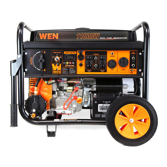
MODEL DF1100X
11000-WATT
DUAL FUEL GENERATOR
Instruction Manual
NEED HELP? CONTACT US!
Have product questions? Need technical support? Please feel free to contact us:
1-800-232-1195 (M-F 8AM-5PM CST)
TECHSUPPORT@WENPRODUCTS.COM
IMPORTANT: Your new tool has been engineered and manufactured to WEN's highest standards for dependability,
ease of operation, and operator safety. When properly cared for, this product will supply you years of rugged,
trouble-free performance. Pay close attention to the rules for safe operation, warnings, and cautions. If you use
your tool properly and for its intended purpose, you will enjoy years of safe, reliable service.
WENPRODUCTS.COM
For replacement parts and the most up-to-date instruction manuals, visit
Advertisement
Table of Contents

Related Manuals for Wen DF1100X


Summary of Contents for Wen DF1100X
- Page 1 1-800-232-1195 (M-F 8AM-5PM CST) TECHSUPPORT@WENPRODUCTS.COM IMPORTANT: Your new tool has been engineered and manufactured to WEN’s highest standards for dependability, ease of operation, and operator safety. When properly cared for, this product will supply you years of rugged, trouble-free performance. Pay close attention to the rules for safe operation, warnings, and cautions. If you use your tool properly and for its intended purpose, you will enjoy years of safe, reliable service.
-
Page 2: Table Of Contents
CONTENTS WELCOME Specifications ....................3 Introduction ..................... 4 SAFETY General Safety Rules ..................5 Generator Safety Warnings ................7 BEFORE OPERATING Know Your Generator ..................10 Unpacking & Packing List ................12 Assembly & Adjustments ................13 Generator Preparation ..................14 OPERATION &... -
Page 3: Welcome
SPECIFICATIONS GENERATOR Model Number DF1100X Surge (Starting) Wattage Gasoline: 11000 Watts, LPG: 9500 Watts Rated (Running) Wattage Gasoline: 8300 Watts, LPG: 7500 Watts Rated Voltage AC: 120V/240V, DC: 12V Rated Amperage AC: 70A/35A, DC: 8A Phase Single Frequency 60 Hz... -
Page 4: Introduction
INTRODUCTION Thanks for purchasing the WEN 11000-Watt Portable Generator. Refer to the illustration below for the location of the serial number on the specifications label. Record the generator information in the spaces provided below. If as- sistance for information or service is required, please contact customer service by calling 1-800-232-1195, M-F 8-5 CST;... -
Page 5: Safety
GENERAL SAFETY RULES WARNING! Read all safety warnings and all instructions. Failure to follow the warnings and instructions may result in electric shock, fire and/or serious injury. Safety is a combination of common sense, staying alert and knowing how your item works. The term “power tool” in the warnings refers to your mains-operated (corded) power tool or battery-operated (cordless) power tool. - Page 6 GENERAL SAFETY RULES WARNING! Read all safety warnings and all instructions. Failure to follow the warnings and instructions may result in electric shock, fire and/or serious injury. Safety is a combination of common sense, staying alert and knowing how your item works. The term “power tool” in the warnings refers to your mains-operated (corded) power tool or battery-operated (cordless) power tool.
-
Page 7: Generator Safety Warnings
GENERATOR SAFETY WARNINGS DANGER! CARBON MONOXIDE Using a generator indoors CAN KILL YOU IN MINUTES. Generator exhaust contains carbon monoxide (CO). This is a poison gas you cannot see or smell. If you can smell the generator exhaust, you are breathing CO. But even if you cannot smell the exhaust, you could be breathing CO. - Page 8 GENERATOR SAFETY WARNINGS WARNING! Do not let comfort or familiarity with the product replace strict adherence to product safety rules. Failure to follow the safety instructions may result in serious personal injury. OPERATING ENVIRONMENT 3. If any part of the generator, electrical device or pow- er cord is broken, damaged, or defective, make sure 1.
- Page 9 GENERATOR SAFETY WARNINGS WARNING! Do not let comfort or familiarity with the product replace strict adherence to product safety rules. Failure to follow the safety instructions may result in serious personal injury. TO MAXIMIZE THE LIFESPAN OF YOUR GENERATOR: We recommend running your generator at least once a month for 20 to 30 minutes.
-
Page 10: Before Operating
KNOW YOUR GENERATOR TOOL PURPOSE Generators provide you with power when and where you need it most. Refer to the following diagrams to become familiarized with all the parts and controls of your Generator. The components will be referred to later in the manual for assembly and operation instructions. - Page 11 KNOW YOUR GENERATOR CONTROL PANEL 1. Engine Key Switch 8. Grounding Nut Start and shut down the engine. Connection point for grounding the generator to the earth. See p. 19 for more information. 2. Data Meter Displays voltage, frequency, total runtime (HHHH), and ses- 9.
-
Page 12: Unpacking & Packing List
UNPACKING & PACKING LIST UNPACKING With the help of a friend or trustworthy foe, such as one of your in-laws, carefully remove the generator from the packaging and place it on a sturdy, flat surface. Make sure to take out all contents and accessories. Do not discard the packaging until everything is removed. -
Page 13: Assembly & Adjustments
ASSEMBLY & ADJUSTMENTS TO INSTALL THE FEET: 1. Insert the M6x25 bolt (32) through the foot support pad (44) and foot support assembly (43). Tighten with an M6 nut (45). 2. Install the foot support assembly (43) onto the frame and tighten with M8 nuts (64). 3. -
Page 14: Generator Preparation
4. Reinstall the oil dipstick and firmly tighten it. Wipe clean any spilled oil. NOTE: Extend the lifespan of your generator by catching the loose metal filaments that naturally build up inside the crank case with the WEN Magnetic Dipstick (Model GNA273), available for purchase at wenproducts.com. Lower Fill Line... - Page 15 GENERATOR PREPARATION TO CHECK OIL LEVEL (before every subsequent start): Fig. 5 1. Place the generator on a level surface. Make sure the engine is OFF before adding or checking oil. 2. Remove and wipe the dipstick with a clean rag. Upper Limit 3.
- Page 16 GENERATOR PREPARATION TO ADD GASOLINE: Fig. 6 Fuel Fuel Cap 1. Place the generator on a level surface. Make sure the Gauge engine is OFF before adding or checking the fuel. 2. Unscrew the fuel cap (Fig. 6) and set it aside. The fuel cap may be tight and hard to unscrew.
- Page 17 GENERATOR PREPARATION FUEL OPTION B: LIQUID PETROLEUM GAS (LPG) (CONT.) NOTE: LPG regulator inlet pressure is approximately 30 PSI at 0 °F, and 218 PSI at 100 °F. • You can use LPG tanks with Type 1, right hand Acme threads with this generator. Verify that the qualification date on tank has not expired.
- Page 18 GENERATOR PREPARATION STEP 3 - CONNECT THE BATTERY WARNING! BATTERY GIVES OFF EXPLOSIVE HYDROGEN GAS. • Keep battery away from spark, flame, or cigarette. • Do not connect or disconnect battery while generator is running. • Service or use battery only in well ventilated areas. WARNING! Battery contains sulfuric acid.
- Page 19 GENERATOR PREPARATION STEP 4 - GROUND THE GENERATOR Fig. 10 To reduce the risk of electric shock and to maximize safety, the generator should be properly grounded. Ground the generator by tightening the grounding nut on the front control panel (Fig. 10) against a grounding wire. A generally acceptable grounding wire is a No.
-
Page 20: Operation & Maintenance
STARTING THE GENERATOR Before starting the generator, make sure you have read and performed the steps in the “Generator Preparation” sec- tion of this manual. If you are unsure about how to perform any of the steps in this manual please call 1-800-232-1195 (M-F 8-5 CST) for customer service. - Page 21 STARTING THE GENERATOR BEFORE STARTING THE GENERATOR Fig. 11 1. Verify that the generator is outside on a dry, level sur- face. Allow at least two feet of clearance on all sides of the generator. 2. To maximize safety, check that the generator is properly grounded (see “Ground the Generator”).
-
Page 22: Using The Generator
USING YOUR GENERATOR CALCULATING THE WATTAGE OF YOUR DEVICE(S) Connect electrical devices running on AC current according to their wattage requirements. Calculate the total run- ning wattage and starting wattage of the device(s) you wish to connect, and MAKE SURE that they are within the capacity of your generator and the capacity of each individual outlet. - Page 23 USING YOUR GENERATOR CALCULATING THE WATTAGE OF YOUR DEVICE(S) - CONTINUED The chart below serves as a reference for the estimated wattage requirements of common electrical devices. How- ever, do not solely rely on this chart - all electronics and appliances are built differently. Always check the wattage listed on the electrical device before consulting this chart.
- Page 24 USING YOUR GENERATOR CONNECTING ELECTRICAL DEVICES CAUTION: Become familiar with the functions and capacity of each component on the control panel (page 11) before connecting electrical devices. Do not overload generator or individual panel receptacles. Do not connect 50Hz or 3-phase loads to the generator. Follow the steps below to properly connect your device(s) to the generator: 1.
- Page 25 • The CO sensor has a lifetime of about 7 years, and is capable of monitoring its lifetime. If your generator shows an error light several years after purchase, it may be time to replace the CO sensor. Contact WEN customer service...
-
Page 26: Shutting Off The Generator
USING YOUR GENERATOR CHANGING FUELS 1. Before changing the fuel source, make sure the generator is turned off or running under half-load. Do not change fuel when generator is over half-load. 2. If switching from LPG to gasoline, turn off the LPG tank valve and disconnect LPG fuel tank from generator. Then turn ON the fuel valve. -
Page 27: Maintenance
MAINTENANCE RECOMMENDED MAINTENANCE SCHEDULE Proper routine maintenance of the generator will help prolong the life of the machine. Please perform maintenance checks and operations according to the maintenance schedule below, Table 4. If there are any questions about the maintenance procedures listed in this manual, please contact customer service at 1-800-232-1195 (M-F 8-5 CST), or email techsupport@wenproducts.com. - Page 28 MAINTENANCE CLEANING THE GENERATOR Keep the generator clean to prevent improper operation or machine damage from dirt and debris. Inspect all ventila- tion openings on the generator. These openings must be kept clean and unobstructed. If the generator becomes dirty, use a damp cloth to wipe exterior surfaces. Use a soft bristle brush to loosen dirt and oil and use a vacuum to pick up loose dirt.
- Page 29 MAINTENANCE CHECKING/ADDING OIL Check the oil level before each use and every 8 hours of operation. The oil capacity of the generator engine is 37.2 fl. ounces. Add oil when the oil level is low. For proper type and weight of oil refer to “add oil” portion of the “Generator Preparation” section. This is a critical step for proper engine starting.
- Page 30 MAINTENANCE AIR FILTER MAINTENANCE Check every 50 hours of operation (refer to Recommended Maintenance Schedule). Routine maintenance of the air filter helps maintain proper airflow to the carburetor. Occasionally check that the air filter is free of excessive dirt. Clean air filter more frequently in dirty or dusty conditions To inspect and clean the air filter: Fig.
- Page 31 MAINTENANCE SPARK PLUG MAINTENANCE Refer to Recommended Maintenance Schedule for maintaining the spark plug. The spark plug is important for proper engine operation. Check the spark plug regularly to maintain proper engine operation. A good spark plug should be intact, free of deposits, and properly gapped. To inspect or replace the spark plug: Fig.
- Page 32 MAINTENANCE BATTERY MAINTENANCE/STORAGE The battery (part no. DF1100-041) shipped with the generator has been fully charged. The battery will receive charge when the engine is running. Remember to run the generator once a month for 20-30 minutes to charge the battery.
- Page 33 MAINTENANCE TESTING THE GFCI OUTLETS Fig. 22 Test the GFCI outlets monthly. The GFCI outlets have two buttons between the re- ceptacles (refer to Fig. 22): • RESET (upper) • TEST (lower) To test: 1. Start the generator according to the instructions in this manual. Wait a few min- utes for the generator to stabilize its speed and voltage output.
-
Page 34: Transportation & Storage
TRANSPORTATION & STORAGE TRANSPORTING THE GENERATOR To prevent fuel spillage when transporting, be sure to perform the following to your generator: 1. Tighten the fuel cap and make sure the fuel valve is turned OFF. 2. Make sure the engine switch is in the OFF position. 3. -
Page 35: Troubleshooting Guide
Refer to “CO Sensor Information” on p. 25. CO sensor disconnected, re- Connect or install the CO sensor. If an error is shown, contact WEN custom- moved, or faulty. er service for assistance. Also refer to “CO Sensor Information” on p. 25. -
Page 36: Wiring Diagram
WIRING DIAGRAM... -
Page 37: Exploded View & Parts List
EXPLODED VIEW & PARTS LIST GENERATOR... - Page 38 EXPLODED VIEW & PARTS LIST GENERATOR Part No. Description Qty. Part No. Description Qty. DF1100X-001 Alternator Assembly 29.2 DF1100-029.4 Multi-Meter Carbon Brush 29.3 DF475-029.2 12V DC Receptacle DF475-001.1 Assembly 29.4 DF1100-029.9 DC Breaker, 8A DF1100-002 Motor Stand 29.5 DF1100-029.3 AC Breaker, 20A DF1100-003 Bolt M5×230...
- Page 39 DF475-046 Bolt, M8x16 DF475-064 Nut, M6 DF475-047 Clip, 12mm DF475-073 Fuel Tank Cap DF1100-048 Wheel Axle DF475-022 Nut, M5 DF1100X-049 Screw Stud, M4x28 DF1100-067 Handle Bushing DF1100-050 Muffler Bracket DF1100-062 Dustproof Sheet (Left) DF1100-051 Tie Wrap DF1100X-069 Fuel Selector Switch...
- Page 40 EXPLODED VIEW & PARTS LIST ENGINE...
- Page 41 Part No. Description Qty. Exhaust Valve Spring DF1100-101 Crankcase DF1100-128 Seat DF1100-102 Ball Bearing DF1100-129 Push Rod Guide Plate DF1100X-103 Oil Seal DF1100-130 Rocker Assembly Governor Arm Shaft DF1100-104 DF1100-131 Rotator Seal DF1100-105 Governor Arm Shaft DF1100-132 Stud Bolt (Carburetor)
- Page 42 ENGINE Part No. Description Qty. Part No. Description Qty. Cylinder Head Cover DF1100-173 Throttle Return Spring DF1100-157 Gasket Recoil Starter DF1100X-174 DF1100-158 Lock Bolt Assembly Upper Shroud 74.1 DF1100X-174.1 Recoil Starter DF1100-159 Assembly DF1100-175 Air Cleaner Assembly DF1100-160 Flywheel Assembly 75.1...
-
Page 43: Warranty Statement
Contact techsupport@wenproducts.com or 1-800-232-1195 with the following information to make arrangements: your shipping address, phone number, serial number, required part numbers, and proof of purchase. Damaged or defective parts and products may need to be sent to WEN before the replacements can be shipped out. - Page 44 THANKS FOR REMEMBERING V. 2021.10.18...
Need help?
Do you have a question about the DF1100X and is the answer not in the manual?
Questions and answers