BBH SCU Series Installation Manual
Hide thumbs
Also See for SCU Series:
- Programming manual (252 pages) ,
- Installation manual (60 pages) ,
- Installation manual (67 pages)

Subscribe to Our Youtube Channel
Related Manuals for BBH SCU Series


Summary of Contents for BBH SCU Series
- Page 1 Installation Manual English SCU Series FSoE Master and Slaves Read and observe installation manual before initial commissioning/initial startup/ integration of the module! Observe safety instructions! Keep for future use!
- Page 2 Information Installation manual for SCU series devices Status: 06/2022 INFORMATION The German version is the original Version of the installation manual. Contact the manufacturer immediately if the instructions are missing! Always keep the manual at hand! Make sure that the manual is complete! ...
- Page 3 Information HB-37500-810-11-16F-EN SCU Installation Manual - Master and Slaves - SARC Page 3 of 303 Status: 09.06.2022...
-
Page 4: Table Of Contents
Inventories Inventories 1.1. Table of contents 1. Inventories ....................4 1.1. Table of contents 1.2. Table of illustrations 1.3. List of tables 2. Basic information ..................13 2.1. Identification 2.2. Important information for use 2.3. Warranty claims 2.4. Liability exclusion 2.5. - Page 5 5.1. FSoE Master (SCU) 5.2. FSoE-Slaves (SDU, SIO, SSB) 5.2.1. SDU-x 5.2.2. SIO-x 5.2.3. SSB-x-x-x 5.3. Encoder specifications 6. Technical specifications of the SCU series ..........42 6.1. SCU Master 6.1.1. SCU-0-EC/x 6.1.2. SCU-1-EC/x 6.1.3. SCU-2-EC/x 6.2. SCU Slaves 6.2.1.
- Page 6 Inventories 7.6.2. Resolver 7.7. Connection of digital inputs 7.8. Connection of analog inputs 7.9. Connection of position and speed sensors 7.9.1. General information 7.9.2. Assignment of encoder interface 7.9.2.1. ENC 1.1 / ENC 2.1 7.9.2.2. ENC 1.2 / ENC 2.2 7.9.3.
- Page 7 Inventories 10.2.1.3. Classification of digital inputs 10.2.1.3.1. Digital inputs I00 … I13 10.2.1.3.2. Digital inputs I/Os (IQIx) 10.2.1.4. Exemplary connections of digital sensors 10.2.1.4.1. Single-channel sensor, without cross-shorting test 10.2.1.4.2. Single-channel sensor with cross-shorting test 10.2.1.4.3. Dual-channel sensor without time-out and without cross-shorting 10.2.1.4.4.
- Page 8 Inventories 10.3.5. Digital outputs I/Os (IQx) 10.3.5.1. Classification of the I/Os (IQx) when used as output 10.3.5.2. Wiring examples for safe digital outputs I/O ‘s (IQx) 10.3.5.2.1. Wiring single-channel without testing 10.3.5.2.2. Wiring single-channel with testing 10.3.5.2.3. Wiring with safe cut-off circuit 10.3.5.2.4.
- Page 9 Inventories 18.3.1. Specification of the safety requirements 18.3.2. Specification of the safety system 18.3.3. Software specification 18.3.4. Hardware specification 18.3.5. Selection of the SRP/CS and selection of the equipment 18.3.6. Consideration of systematic failures 18.3.7. Fault exclusions 18.3.8. Hardware design and software design 18.3.8.1.
-
Page 10: Table Of Illustrations
Inventories 1.2. Table of illustrations Fig. 1: rating plated SCU-2-EC/NM ................28 Fig. 2:Network EtherCAT ..................32 Fig. 3:example FSoE Netzwerk FSoE ................. 33 Fig. 4: strucutre of SCU-2-EC/NM ................35 Fig 5: structure of SCU-1-EC ................... 35 Fig. 6: structure of SDU-11-PXV ................36 Fig. - Page 11 Inventories Fig. 50: TwinCAT – setting Slaves ................154 Fig. 51: TwinCAT - linking ..................155 Fig. 52: TwinCAT – insert SDC ................. 156 Fig. 53: TwinCAT - Task ..................156 Fig .54: TwinCAT connection .................. 157 Fig. 55: TwinCAT – time parameters ................ 158 Fig.
-
Page 12: List Of Tables
Inventories 1.3. List of tables Table 1: reaction time .................... 77 Table 2: calculation of response time without Overspeed ..........82 Table 3: calculation of response time with Overspeed ..........82 Table 4: 7-segment display ..................138 Table 5: types of Reset ..................139 Table 6: Reset functions .................. -
Page 13: Basic Information
In case of ambiguities or further information requirements, please contact BBH Products GmbH. HB-37500-810-11-16F-EN SCU Installation Manual - Master and Slaves - SARC Page 13 of 303 Status: 09.06.2022... -
Page 14: Warranty Claims
Liability exclusion Observance of this documentation and the documentation on the connected devices from BBH Products GmbH is a basic prerequisite for safe operation and for achieving the specified product properties and performance characteristics. BBH Products GmbH assumes no liability for personal injury, property damage or financial loss resulting from non-observance of the documentation. -
Page 15: Supplied Documents
➔ Print of programming software • Inspection report (TÜV inspection report for type release of the assemblies SCU, etc.): ➔ Inspeciton report SCU series. • Manufacturer documentation of the components integrated via the bus, and of the directly integrated components. -
Page 16: Symbols And Signal Words
Basic information 2.8. Symbols and signal words The following symbols and signal words are used in this documentation. The combination of a pictogram and a signal word classifies the respective safety note. The symbol may vary depending on the type of hazard. Symbol Signal word Description... -
Page 17: Safety
In case of ambiguities or further information requirements, please contact BBH Products. 3.1. General safety information ... -
Page 18: Target Group
Safety The underlying regulations are the EMC test regulations EN 55011 and EN 61000-5-2. NOTICE The valid VDE regulations and other special safety regulations must be observed. NOTICE The configured monitoring functions, as well as their parameters and their links must be proved by a validation report. WARNING Inputs and outputs for standard functions, as well as digital data and analogue data transmitted by communication units must not be used for... - Page 19 Safety The following table explains the competencies of the target groups in detail: Target group Requirement and knowledge project developer Basic technical education (technical college, engineering education or equivalent work experience). Knowledge of: ▪ the operation of a PLC, safety regulations, ▪...
-
Page 20: Terms
Information 3.3. Terms The SCU assemblies manufactured by BBH Products GmbH serve to implement safety-relevant functions by safe communication via FSoE and non-safe communication by means of EtherCAT. These are always having a two-channel design: systen A and system B. -
Page 21: Relevant Standards And Directives
Safety 3.4. Relevant standards and directives The following standards have been considered for development and implementationei der Entwicklung und Umsetzung berücksichtigt: • DIN EN ISO 13849-1:2015 Sicherheit von Maschinen – Sicherheitsbezogene Teile von Steuerungen • IEC 61508-1:2011-02 Funktionale Sicherheit sicherheitsbezogener elektrischer / elektronischer/programmierbarer elektronischer Systeme •... -
Page 22: Intended Use
EN 574. The SCU series may only be used for the applications specified in the technical description and in compliance with the described general technical conditions. -
Page 23: Storage And Transport
The information concerning transport, storage and appropriate handling must be observed. The climatic conditions indicated in the chapter “Technical specifications of the SCU series” must be observed. NOTICE For storage and transport, the conciitions according to EN 60068-2-6 must be observed with respect to the values indicated under “Technical specifications of the SCU series”. -
Page 24: Placement
Other products must be used for these applications! The EN ISO 13849-1 standard and other functional safety standards have been taken into account in the engineering of the SCU series assemblies. CAUTION Destruction of the assembly or the control system in case of... -
Page 25: Electrical Connection
BBH. Furthermore, it is requested that safe products that have failed due to a defect and are considered beyond repair be sent to BBH for analysis. Liability and warranty of the manufacturer are excluded, if the damages... -
Page 26: Behaviour In Case Of Emergencies
Safety CAUTION Fire hazard in case of component failure Provide adequate fuse protection for the 24 V DC power supply of the control system in the end application! (Information on this can be found in the Power supply section). 3.9. Behaviour in case of emergencies The SCU units have been developed and built to be able to autonomously recognize failures by means of diagnostics and to autonomously change into the safe status... -
Page 27: Scope Of Delivery Scu
Information 3.11. Scope of delivery SCU The assemblies of the SCU series are delivered with the input connectors, the output connectors and the power supply connectors. The assemblies are enclosed in the product informaton of the SCU series. Among others, the product information includes the link to download the complete documentatkion. -
Page 28: Labelling / Rating Plate Scu
3.12. Labelling / rating plate SCU The rating plate is mounted on the left sidewall of the assembly, and contains the following information: • Type = Type designation • Product No.: = Product number • Serial No.: = Serial number •... -
Page 29: Rating Plate Ssb-X-X-X
3.12.1. Rating plate SSB-x-x-x The rating plated SSB-x-x-x contains the following information: (1) Type : Type designation CE Mark of conformity (3) Date: Manufacture date (week number / year) (4) HW-Release: Hardware Version (5) FW-Release: Firmware Version (6) Product No.: Product number decimal with barcode (7) Serial No.: Serial number decimal (8) Power:... -
Page 30: Use
4.1. Device description 4.1.1. Function SCU-x-EC (in short: SCU) are master units for FSoE communication. SCU-1-EC and SCU-2-EC serve to read encoder data and switchning states from FSoE Slave units (e. g. SSB, SIO, SDU) and from external FSoE devices to implement safety functions. -
Page 31: Embedding Into The Ethercat Network And Into Fsoe
4.1.2. Embedding into the EtherCAT network and into FSoE 4.1.2.1. FSoE data transfer FSoE (Fail Safe over EtherCAT) is the safe data transfer via the EtherCAT network. The application data are bundled into data packages and are additionally supplemented with unique identifications and unique checksums. Additionally, FSoE is monitored via timer (Watchdog). -
Page 32: Ethercat Data Transfer
Data transfer is always initiated by the Master. – Data transfer takes place in the EtherCAT network with an optimum transfer time of some µs. Master In Out In Out In Out In Out In Out Slave Slave Slave Slave Fig. - Page 33 SIO = Safe IO Slave assembly by BBH to import IOs • SDU = Safe Drive Unit Slave assembly by BBH to import one axle • SSB = Safe Sensor Box Slave assembly by BBH to import 6 axles Generally, also assemblies by other manufacturers can be integrated, if they offer an FSoE communication.
-
Page 34: The Principle Of Safe Monitoring With Scu
The principle of safe monitoring with SCU The SCU master assembly receives the data of inputs and axles from the Slave assemblies (e. g. SIO, SDU, SSB by BBH Products or FSoE slaves by other manufacturer) and analyzes the received data. -
Page 35: General Structure Of The Scu Assemblies
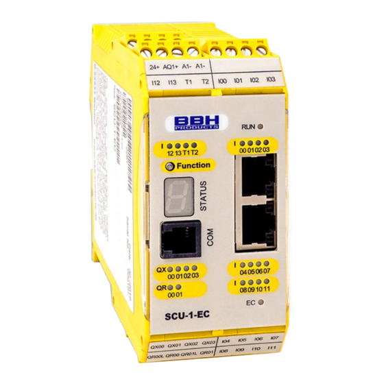
General structure of the SCU assemblies General structure of the SCU assemblies The series SCU consists of: • FSoE Mastern (SCU) • FSoE Slaves (SDU, SIO, SSB) The -S variants of the assemblies are identical to the standard devices 5.1. FSoE Master (SCU) In general, the SCU assemblies (SCU-0-EC/x, SCU-1-EC/x and SCU-2-EC/x) are structured as follows:... -
Page 36: Fsoe-Slaves (Sdu, Sio, Ssb)
General structure of the SCU assemblies (36) LED display status fieldbus interface (32) Connection terminal IOs (37) Connection socket fieldbus (33) Connection terminal IOs (38) Connection socket fieldbus (34) Connection terminal IOs ONLY /NM-variants: (35) Memory card slot 5.2. FSoE-Slaves (SDU, SIO, SSB) 5.2.1. - Page 37 General structure of the SCU assemblies (10) (11) (12) (15) (16) (14) (13) (17) (19) (18) (20) (21) (22) (27) (26) (23) (25) (24) Fig. 7: structure of SDU-22A Connection terminal voltage supply (18) LED display status outputs Connection terminal inputs, clock outputs (19) LED display status inputs Connection terminal inputs (20) LED display status inputs...
-
Page 38: Sio-X
General structure of the SCU assemblies 5.2.2. SIO-x (10) (12) (11) (13) (14) (15) (20) (16) (19) (18) (17) (26) (21) (25) (22) (24) (23) Fig. 8: structure SIO-2 Connection terminal voltage supply (14) Connection socket service interface Connection terminal inputs, (15) LED display status outputs clock outputs (16) LED display status outputs... -
Page 39: Ssb-X-X-X
General structure of the SCU assemblies 5.2.3. SSB-x-x-x Fig. 9: structure of SSB-6-x* (1) Connection encoder interfaces (7) Connection socket outputs (optional) (2) STATUS-LED display system status (8) Connection socket voltage supply, (3) 7 segment display – system status inputs (optional) (4) LED dispay status EtherCAT-connection (5) Connection socket EtherCAT-cable (IN) (6) Connection socket EtherCAT-cable... -
Page 40: Encoder Specifications
General structure of the SCU assemblies 5.3. Encoder specifications Incremental-TTL Physical Layer RS-422 compatible Measuring signal A/B Track with 90 degree phase difference Max. frequency of input cycles 200 kHz / 250 kHz (ENC 1.1, ENC 2.1 / ENC 1.2, ENC 2.2) Type of connection D-SUB 9pol Sin / Cos... - Page 41 General structure of the SCU assemblies Type of connection (X27, X28, X29, Plug-in terminals with spring or screw connection X30) Proxi (HTL proximity sensor) Signal level 24V / 0V Max. counting pulse frequency 10 kHz (switching logic debounced) Pulse width 50 µsec Type of connection (X23) Plug-in terminals with spring or screw connection...
-
Page 42: Technical Specifications Of The Scu Series
Technical specifications of the SCU series Technical specifications of the SCU series 6.1. SCU Master 6.1.1. SCU-0-EC/x Specification sheet ▪ General technical data ▪ Dimensions: SCU-0-EC , SCU-0-EC/NM ▪ 6.1.2. SCU-1-EC/x Specification sheet ▪ General technical data ▪ Dimensions: SCU-1-EC , SCU-1-EC/NM ▪... -
Page 43: Ssb-X-X-X
Technical specifications of the SCU series 6.2.5. SDU-21 Specifiction sheet ▪ General technical specifications ▪ Dimensions ▪ 6.2.6. SDU-21A Specification sheet ▪ General technical specifications ▪ Dimensions ▪ 6.2.7. SDU-22 Specification sheet ▪ General technical specifications ▪ Dimensions ▪ 6.2.8. SDU-22A Specification sheet ▪... -
Page 44: Additional Information
Technical specifications of the SCU series 6.3. Additional information 6.3.1. Cable lengths EtherCAT IN < 100m EtherCAT OUT < 100m Digital inputs < 30m *) Digital outputs (type1, type2, message, pulses) < 30m Relay outputs < 30m Note *): Use of screened cables. Unscreened cables can be used under the following restrictions •... -
Page 45: Connection And Installation
Connection and installation Connection and installation 7.1. General notes on installation Strictly follow the safety regulations when installing! Protection class IP20 Route all signal lines for the interfacing of digital inputs and contact monitoring separately. You should in any case disconnect 230VAC (120VAC cULus) voltages from low voltage power lines, if these voltages are used in connection with the application. - Page 46 Connection and installation cable and the connection of the braking resistor. The installation guidelines of the converter manufacturer must be observed. • All contactors in the environment of the power converter must be equipped with appropriate suppressor circuits. • Suitable measures must be taken to protect against overvoltages. Symbols used according to UL 61010-1 Symbol 14 •...
-
Page 47: Installation / Mounting
Connection and installation 7.2. Installation / mounting NOTICE Spare parts or consumables For the SCU assembly no spare parts or consumables are available. If need be, the assembly must be exchanged altogether. Opening or disassembling the SCU assembly is not permitted. NOTICE Mounting location The SCU assembly is exclusively installed in switch cabinets that at leas... -
Page 48: Wiring
Connection and installation 7.3. Wiring DANGER Work on the wiring or work at the electrical system can cause electric shock. Electric shock can cause death. Thus, only persons qualified according to TRBS 1203 may carry out work on the wiring or work on the electrical system. -
Page 49: Scu Master Scu-0-Ec/X
Connection and installation 7.4. Terminal schemes 7.4.1. SCU Master SCU-0-EC/x ▪ ▪ SCU-1-EC/x ▪ SCU-2-EC/x 7.4.2. SCU Slaves ▪ SDU-11 ▪ SDU-11/NM ▪ SDU-11-PXV ▪ SDU-12 ▪ SDU-21 ▪ SDU-21A ▪ SDU-22 ▪ SDU-22A ▪ SIO-1 ▪ SIO-2 ▪ SSB-6-EnDAT-x ▪... -
Page 50: External Dc 24 V - Voltage Supply
Connection and installation 7.5. External DC 24 V – voltage supply The SCU module requires a 24 VDC power supply (see SELV or PELV, EN50178). The following boundary conditions must be observed during project planning and installation of the intended power supply unit: Observe the minimum and maximum tolerance of the supply voltage. - Page 51 Connection and installation Note: Terminals GND_ENC and A1- are not internally connected to GND! CPU-ENC EXT-ENC EXT-ENC GND- GND- GND- GND- Encoder Encoder Encoder Encoder ENC 1.1 ENC 1.2 ENC 2.2 ENC 2.1 SDU-22 Internal connection e.g.: between UE1- -> 9-pin D-SUB ENC 1.1 Pin 2 HB-37500-810-11-16F-EN SCU Installation Manual - Master and Slaves - SARC Page 51 of 303 Status: 09.06.2022...
-
Page 52: Connection Of The External Encoder Supply
Connection and installation 7.6. Connection of the external encoder supply 7.6.1. Incremental, HTL, SIN/COS, SSI L-_ENC1-2 L-_ENC2-2 L+_ENC1-2 L+_ENC2-2 L-_ENC1 L-_ENC2 L+_ENC1 L+_ENC2 Voltage supply of the external encoder supply 1) only SDU-12 and SDU-22 2) only SDU-21 and SDU-22 3) only SDU-22 The SDU module supports encoder voltages of 5 V, 8 V, 10 V, 12 V, 20 V and 24 V, that are monitored internally according to the selected configuration in SafePLC2. -
Page 53: Resolver
Connection and installation Monitoring of the supply voltage in accordance with the chosen nominal voltage: Nominal voltage Minimum voltage Maximum voltage 5 V DC 4,4 V DC 5,6 V DC 8 V DC 7 V DC 9 V DC 10 V DC 8 V DC 12 V DC 12 V DC... -
Page 54: Connection Of Digital Inputs
A detected fault will set the module into an alarm status. At the same time all outputs of the module are rendered passive. Besides the actual signal inputs, the SCU series hold two clock outputs T1 and T2 available. The clock outputs are switching-type 24 VDC outputs. -
Page 55: Connection Of Analog Inputs
Connection and installation Each input can be configured individually fort he following signal sources: Input is assigned to the cycle T1 Input is assigned to the cycle T2 Input assigned to continous voltage DC 24 V 7.8. Connection of analog inputs With the executions with analog processing. -
Page 56: Connection Of Position And Speed Sensors
Connection and installation 7.9. Connection of position and speed sensors 7.9.1. General information Depending on module type the device has external encoder interfaces for the connection of industrial incremental and absolute encoders. The encoder interfaces can be configured as incremental, SIN/COS, or as absolute SSI-encoders. It is also possible to connect 2 incremental signal generating sensors (e.g. - Page 57 Connection and installation SAFETY NOTE • The GND connections of the encoders must be connected to the GND of the slave module. This applies in the same way also to resolvers. • ATTENTION • The sensor connections must neither be plugged on nor pulled off during operation.
-
Page 58: Assignment Of Encoder Interface
Connection and installation 7.9.2. Assignment of encoder interface 7.9.2.1. ENC 1.1 / ENC 2.1 Sensor assignment Incremental - Encoder SIN/COS Absolut - Encoder SSI - Listener only SDU-21 7.9.2.2. ENC 1.2 / ENC 2.2 Sensor assignment SIN/COS Resolver Incremental - Encoder SSI –... -
Page 59: Connection Varaints
Connection and installation 7.9.3. Connection varaints 7.9.3.1. Connection of an absolute encoder as master n.c. Pin 1 Ground Pin 2 GND der GND of the supply voltage Versorgungsspannung 24 V DC Pin 3 n.c. Pin 4 CLK- absolute Sub-D Sub-D- Pin 5 DATA+ Absolut-... -
Page 60: Connection Of An Absolute Encoder As Slave
Connection and installation 7.9.3.2. Connection of an absolute encoder as slave n.c. Pin 1 Pin 2 Ground Pin 3 n.c. Pin 4 CLK- Absolute Sub-D Sub-D- Pin 5 DATA+ Absolut- encoder Stecker plug Encoder (9 polig) Slave mode (9 pin) (Slave-Betrieb) Pin 6 DATA-... -
Page 61: Connecting An Incremental Encoder With Ttl-Signal Level
Connection and installation 7.9.3.3. Connecting an incremental encoder with TTL-Signal level n.c. Pin 1 Pin 2 Ground Pin 3 n.c. Pin 4 Sub-D Incremental Sub-D- Pin 5 plug Inkremental encoder Stecker Encoder (9 pin) (9 polig) Pin 6 n.c. Pin 7 Pin 8 Pin 9 Versorgungsspannung... -
Page 62: Connection Of A Sin/Cos Encoder
Connection and installation 7.9.3.4. Connection of a SIN/COS encoder n.c. Pin 1 Pin 2 Ground GND der GND of the supply Versorgungsspannung voltage 24 V DC Pin 3 n.c. 24 V DC Pin 4 COS- SIN/COS Sub-D Sub-D- Pin 5 SIN+ encoder plug... -
Page 63: Connection Of A Resolver As Master
Connection and installation 7.9.3.5. Connection of a resolver as master Reference Out + Pin 1 Reference Out - Pin 2 Reference In + Pin 3 Pin 4 COS - GND of the supply Resolver voltage 24 V DC Sub-D Sub-D- Pin 5 SIN + (Master... -
Page 64: Connection Of A Resolvers As Slave
Connection and installation 7.9.3.6. Connection of a resolvers as slave Pin 1 Monitor Reference Pin 2 Voltage GND Reference In + Pin 3 Pin 4 COS - Sub-D Resolver Sub-D- Pin 5 SIN + plug (Slave mode) Stecker Resolver (9 pin) (9 polig) (Slave-Betrieb) Pin 6... -
Page 65: Connection Of Proximity Switch Sdu-1X/-2X
Connection and installation 7.9.3.7. Connection of proximity switch SDU-1x/-2x The connection is made via plug connector X23 on the digital I4 …I7. The exact pin assignment depends on the encoder type and is shown in the connecting plan of the programming interface. NOTICE When using HTL-encoders please bear in mind that the tracks A+ and B+ or A- and B- must be combined accordingly. -
Page 66: Htl-Encoder With A+ Or B+- Signal
Connection and installation 7.9.3.8.2. HTL-encoder with A+ or B+- signal Klemmleiste Terminal strip Inkremental Encoder Klemmleiste Terminal strip Versorgungsspannung Supply voltage Terminal Klemmleiste strip Ground Power supply Spannungsversorgung Encoder Geber SDU-12 Encoder 3 SDU-22 Encoder 4 HB-37500-810-11-16F-EN SCU Installation Manual - Master and Slaves - SARC Page 66 of 303 Status: 09.06.2022... -
Page 67: Configuration Of Measuring Distances
Connection and installation 7.10. Configuration of measuring distances 7.10.1. Genreal description of encoder configuration The most important input variables for the monitoring functions of the module are safe position, speed and acceleration. These are obtained by dual-channel generation from the connected sensor system. A category 4 compliant architecture, i.e. continuous dual- channel recording with high degree of diagnostic coverage, is required for Pl e acc. -
Page 68: Sensor Type Diagnoses
Sensor type diagnoses Sensor type diagnoses Absolute encoder and incremental measuring systems are possible, as well as counting pulse generating proximity switches. 8.1. Absolute encoder: Data interface: Serial Synchron Interface (SSI) with variable data length from 12 to 28 bit. Data format: Binary or Gray code, Physical Layer: RS-422 compatible... - Page 69 Sensor type diagnoses Parameterization of SSI-format: ClkN Anzahl Clk = Framelength Start Clk 0 Clk 1 Clk 2 Index Daten Index Status K Daten O Status Status information Status Status Status Status ..Fault mask Error Maske Mask Mask Mask Mask 0 = don’t care 0 = dont´t care...
-
Page 70: Incremental Encoder
Sensor type diagnoses 8.2. Incremental encoder: Physical Layer: RS-422 compatible Measuring signal A/B: Track with 90-degree phase difference Maximum frequency of input cycles: 200 KHz or 500 kHz Diagnoses: Diagnosis Parameters Fault threshold Supply voltage monitoring Fixed values +/- 20% +/-2% 5 V, 8 V, 10 V, 12 V, (measuring tolerance) 20 V, 24 V... -
Page 71: Sinuscosinus Encoder - High Resolution Mode
Sensor type diagnoses 8.4. SinusCosinus encoder – High resolution mode: Physical Layer: +/- 0.5 Vss (without voltage offset) Measuring signal A/B: Track with 90 degree phase difference Maximum frequency of input clock pulses: 15 kHz Diagnosen: Diagnosis Parameters Fault threshold Supply voltage monitoring Fixed values +/- 20 % +/-2 %... -
Page 72: Extended Monitoring Proximity Switch / Proximity Switch
Sensor type diagnoses 8.6. Extended monitoring Proximity switch / proximity switch The extended monitoring uncovers the following faults: a) Supply voltage failure b) Failure of output signal in driver direction c) Malfunction of High signal proximity switch d) Interruption of signal path e) Mechanical de-adjustment of proximity switch / excessive switching distance of proximity switch For diagnostic purposes both status conditions of the counting signal are additionally... -
Page 73: Htl - Sensor
Sensor type diagnoses Reading in counting signals: The two counting signals are both separately assigned to the two channels. In each of the channels the status is read in synchronously. In order to ensure synchronization this must be carried out directly after the channel synchronization. Sampling must take place at least 1x per cycle. -
Page 74: Resolver
Sensor type diagnoses 8.8. Resolver Measuring signal: SIN/COS – track with 90° phase difference Max. counting clock frequency: 2 kHz/ pole Resolution: 9 bit / pole Master-Mode: Frequency reference signal: 8 kHz Slave-Mode Frequency reference signal: 4 - 16 kHz Reference signal form: Sinusoidal, triangle, rectangle on Enc 1.1/Enc 2.1... -
Page 75: Reaction Time
Reaction time Reaction time The reaction period is an important safety feature. The reaction time must be considered for every application / for every applicative safety function. The following chapter lists the reaction periods for particular functions. If need be, the reaction periods are listed in relation to other parameters. - Page 76 Reaction time Reaction time [ms] Function Explanation Worst Typical -case Activation of one input, logic Activation of digital output processing and switching of the via digital input output Activation of relay output via Activation of one input and switching digital input oft he output Deactivaton of digital output Deactivation of one input and thus...
- Page 77 Reaction time Reaction time [ms] Function Explanation Worst Typical -case If the monitoring function that has already been activated by ENABLE, the Reaction of an already block needs one cycle to calculate the activated monitoring current speed value. In the next cycle, function including PLC edit after the monitoring function has been in case of position processing...
- Page 78 Reaction time This results in the following formulae for the typical reaction time: • Reading in of digital input of FSoE Slave on digital output of Master = 2*T + x * T + 2*T Slave ECAT zyklus • Reading in of digital input of SCU on digital output of FSoESlave = 1.5*T + x*T + 1.5*T...
-
Page 79: Response Time Of Fsoe In Fastchannel Operation
Reaction time 9.2. Response time of FSoE in Fastchannel operation: The basis of the calculation of response times of the Fastchannel connection is the Fast Chanel processing time + transmission time EtherCAT. Fast Channel processing time: = 2 ms. FCcycle Transmission time: = 4 ms. -
Page 80: Response Times For Error Distance Monitoring
Reaction time 9.3. Response times for error distance monitoring The following calculation scheme results for the calculation of the WorstCase conditions: System’s speed at the time of scanning V(t) System’s speed at the reaction of the SCU: A1 = without filter A2 = with filter Threshold value (t for monitoring SLS or SCA): V... - Page 81 Reaction time Diagramm 1: Drive response with / without overspeed distance HB-37500-810-11-16F-EN SCU Installation Manual - Master and Slaves - SARC Page 81 of 303 Status: 09.06.2022...
- Page 82 Reaction time The following applies for the courses of V and s the following relations result without Overspeed distance: Parameters Method of calculation Remark Deceleration time in external Value from information about disabling string from response time SCU + information by relay Reakt Deceleration time in external manufacturer / contactor...
-
Page 83: Safety-Related Characteristics
Safety-related characteristics Safety-related characteristics 10.1. Internal architecture The internal structure of the SCU units follows category 4 according to EN 13849-1: Two separate channels with mutual comparison of results. Additionally, high-grade diagnostics are carried out for error recognition. Aktuator Fig. 11: 2-channel architecture Thus, the total architecture shows the following structure: Eingang/ Ausgang/... - Page 84 Safety-related characteristics Safety-related characteristic data: Max. achievable safety class SIL 3 according to IEC 61508 Category 4 according to EN ISO 13849-1 Performance level e according to EN ISO 13849-1 System structure 2-channel with diagnostics (1002) according to IEC 61508, Architecture category 4 according to EN ISO 13849-1 Design of the operating mode „high demand“...
-
Page 85: Safety Related Characteristic Data And Wiring For The Connected Sensors
Safety-related characteristics 10.2. Safety related characteristic data and wiring for the connected sensors Each SCU unit has completely separated signal processing paths for every safety input. This applies for both the digital and the analog inputs. Furthermore, measures for achieving the highest possible DC-values have been implemented. 10.2.1. -
Page 86: Dc Of Digital Sensors / Inputs
Safety-related characteristics Sensor Actuator Fig. 15: digital sensor one-channel One-channel input element and two-channel processing at low to medium DC due to two-channel signal processing and diagnostics by means of cyclical testing. PL / SIL dependent on permissible fault exclusions and on the test rate of input element. 10.2.1.2. - Page 87 Safety-related characteristics parallel signal lines or adjacent terminal assignment, cross-shorting between the respective input elements is detected. Sensors / input elements with 2- or multipole contacts without time-out: Several contacts can be assigned to the sensors / input elements. These are therefore compatible with at least 2-channel elements.
- Page 88 Safety-related characteristics The following diagnoses for input sensors can generally be used for the safety related assessment of the entire system: Input Parameterized / Definition of measure Note element operational tests characteristic Single-channel Cyclic test pulse by A sufficiently high dynamic change of input test rate must be >60...
- Page 89 Safety-related characteristics as well as logic program sequence monitoring and detection of static failures and short circuits (for multiple inputs/outputs). Plausibility test, e.g. use of Only effective in normally open and connection with normally closed contacts = activated time-out non-equivalent signal function for input comparison of input element...
-
Page 90: Classification Of Digital Inputs
Safety-related characteristics 10.2.1.3. Classification of digital inputs 10.2.1.3.1. Digital inputs I00 … I13 Device type Digital Achievable Comment inputs performance level Suitable for any kind of input elements, with / without pulse, SCU-x-EC, I00 … I13 PL e achievable PL depending on the MTTF SIO-x of the input element, as well as fault exclusions in the external wiring. -
Page 91: Digital Inputs I00
Safety-related characteristics 10.2.1.3.2. Digital inputs I/Os (IQIx) Digital Achievable Comment inputs performance level Without pulse, single channel static signal -> auxiliary input Without pulse, dual channel static signal At least one request/day required by PL e application Fault detection only upon request Without pulse, dual channel static signal Less than one request/day required by PL d... -
Page 92: Exemplary Connections Of Digital Sensors
Safety-related characteristics 10.2.1.4. Exemplary connections of digital sensors 10.2.1.4.1. Single-channel sensor, without cross-shorting test Fig. 16: Single-Channel sensor, without cross-shorting test The single-channel sensor is connected to the SCU module without clocking or without cross-shorting test. This design is not recommended for safety applications. - Page 93 Safety-related characteristics When using a single-channel sensor with clocking, the power supply of the switching element is attached to the clock output T1 or T2. The clock must subsequently be assigned to the SCU. The use of a single-channel sensor with clock detects: short-circuit to supply voltage DC 24 V short-circuit to DC 0 V cable interruption (current interruption is safe state!)
-
Page 94: Dual-Channel Sensor Without Time-Out And Without Cross-Shorting
Safety-related characteristics 10.2.1.4.3. Dual-channel sensor without time-out and without cross- shorting Faults are at least detected when requested. The DC is medium and by using cyclic tests (start test, operational/organizational tests) can be changed up to high level. depending on the test frequency. Only normally closed contacts should be used for safety related applications. - Page 95 Safety-related characteristics SAFETY NOTE • PL d or higher in accordance with EN ISO 13849-1 is achieved by using switching elements / sensors with positively opening contacts or positive actuation acc. to EN 60947-5-1 • Using devices for which the fault exclusion double fault for the intended safety level can be specified for the switching elements, is permitted.
-
Page 96: Dual-Channel Sensor With Time-Out And Cross-Shorting Test
Safety-related characteristics 10.2.1.4.4. Dual-channel sensor with time-out and cross-shorting test Cross-shorting as well as connections to DC 24 V and DC 0 V can be detected by using two independent clock signals on the homogeneous sensor. PL d or higher acc. to EN ISO 13849-1 can be achieved when: - Use of sensors/switching elements with forced actuation. -
Page 97: Overview Of Achievable Pl For Digital Safety Inputs
Safety-related characteristics 10.2.1.5. Overview of achievable PL for digital safety inputs Type of Input Parameterized / Achie- Fault exclusion Condition for input Sensor / operational tests vable PL for input element element input acc. to element EN ISO 13849-1 Operation proven input element All faults at the MTTF... - Page 98 Safety-related characteristics Short-circuit between Connection in input/signal line control cabinet or Dual- (only with protected routing channel common parallel switching elements = 2xNO MTTF = high or 2xNC Short-circuit at Connection in input/signal line control cabinet or protected routing Getting caught / positively disconnecting MTTF...
-
Page 99: Sensors For Speed And/Or Position Detection
10.2.2.1. General safety related structure of sensor interface for position and/or speed The SDU-x modules of the SCU series are equipped with one (SDU-11), or two encoder interfaces (SDU-12/-22) per axis. Depending on encoder type and combination, different safety levels can be reached. -
Page 100: General Diagnostic Measures For Encoder Interface
10.2.2.2. General diagnostic measures for encoder interface For fault detection in the sensor system the SCU series (SDU modules) has a number of diagnostic measures implemented, depending on the chosen encoder type or its combination. These are automatically activated when choosing the encoder type. -
Page 101: Encodertypen Und Deren Kombination, Diagnosekenndaten
Safety-related characteristics 10.2.2.3. Encodertypen und deren Kombination, Diagnosekenndaten 2-channel Safe 2-channel Safe Safe 1-channel partial system Encoder A Encoder B absolut Fault exclusion partial speed direction partial non-dynamic Position system system (standstill- dynamic monitoring) 1 x Proxi 1 x Proxi Operating Actuator ***) n.a. - Page 102 Safety-related characteristics 2-channel Safe 2-channel Safe Safe 1-channel partial system Encoder A Encoder B absolut Fault exclusion partial speed direction partial non-dynamic Position system system (standstill- dynamic monitoring) SIN/COS Resolver n.a. SIN/COS n.a. 95-99% 2 x counter Proxi n.a. 90-95% 90°...
- Page 103 Safety-related characteristics For SINCOS encoders suitable for safety applications (see notes on this under...), a DC of 90% can be applied for the single-channel transmit LED. **) The connection code disc / shaft as well as the sensor embodiment must be analyzed in detail. For a possible fault exclusion, the relevant notes in the standard EN/IEC 61800-5-2, Annex D.3.16 (Table D.8) must be observed.
-
Page 104: Specific Diagnostic Measures With Regard To The Encoder Type Used
Safety-related characteristics 10.2.2.4. Specific diagnostic measures with regard to the encoder type used Encoder type Incremental SIN/COS Proxi 2 x counting input Proxi 1 x counting input Incremental Resolver SIN/COS Only in High-Resolution Mode measures for encoder interface Safe PXV: Checking the transmission of the safe position via CRC32 Analysis and evaluation of the error bits of the encoder Plausibility check of the code band by dynamic color switching... -
Page 105: Safety-Related Switch-Off Threshold Encoder Systems For Position And Speed Detection
Safety-related characteristics 10.2.2.5. Safety-related switch-off threshold encoder systems for position and speed detection Plausibility tests with the current position and speed values are performed between both measuring channels A and B of the SCU module as a basic measure, which are then checked against parameterizable thresholds. - Page 106 Safety-related characteristics Digital accelaration resolution The digital acceleration resolution is limited by a maximum peak time of 256 ms and the encoder resolution. The garphs below show the lowest measurable acceleration in dependence on the resolution in revolutions/min, mm/s² and m/s². Value Acceleration [rev/min/s] Resolution...
- Page 107 Safety-related characteristics SAFETY NOTE • The fault can be optimized by choosing a suitable sensor resolution for the corresponding application. • For applications with limited resolution and/or time variance of the sensing signal, the functional performance of the monitoring function used can be improved by using an average filter.
-
Page 108: Safety-Related Evaluation Of Encoder Systems, Resolvers Or Their Combination
Safety-related characteristics 10.2.2.6. Safety-related evaluation of encoder systems, resolvers or their combination Due to the monitoring functions implemented in the SCU-series, no special demands are initially made on the internal design of the encoder electronics in applications with encoder systems, i.e. standard encoders can normally be used. A safety related assessment of the overall arrangement must generally be made. - Page 109 Safety-related characteristics generated independently from each other and Common-Cause faults can be ruled out. Evidence of the mechanical design, e.g. fastening of the code disc on the shaft, must also be provided. Encoders with proven safety related characteristics should preferably be used. ...
-
Page 110: Analog Sensors
Safety-related characteristics 10.2.3. Analog sensors The FSoE Slave-modules SDU-21A and SDU-22A have two analog inputs with two input channels each. Only 2-channel sensors can generally be connected to this interface. The internal signal processing takes place separately in the two channels with cross- comparison of the results. -
Page 111: Exemplary Connection Of Analog Sensors
Safety-related characteristics • If several sensor systems are required for the correct function of a single safety function, their partial values must be correctly merged by following the chosen method. This applies also for a combination of digital and analog sensors (e.g. safely reduced speed with open safety door = door contact + encoder for speed detection) 10.2.3.1. -
Page 112: Voltage Sensor With Test Pulse
Safety-related characteristics 10.2.3.1.2. Voltage sensor with test pulse 1 UE1+ 2 UE1- 3 QY00 4 QY01 X25/26 Voltage sensor 1 -AIN 1+ Spannungssensor with test input 2 -AIN 1- mit Testeingang for signal stroke für Signalhub 3 -AIN 2+ 4 -AIN 2- 10.2.3.1.3. -
Page 113: Safety Related Characteristic Data And Wiring Of The Outputs
Safety-related characteristics 10.3. Safety related characteristic data and wiring of the outputs The SCU/SDU-modules all have safe outputs of various types. For wiring, the corresponding characteristic as specified in the following description, must be accounted for. 10.3.1. Charakteristic of output elements Aktuator Single-channel output and single-channel actuator without diagnostics Aktuator... - Page 114 Safety-related characteristics Aktuator Single-channel output with internal dual-channel processing (IQx) and dual-channel actuator with at least single-channel diagnostic Aktuator Single-channel output with internal dual-channel processing (IQx) and dual-channel actuator with dual-channel diagnostic Aktuator Dual-channel output and dual-channel actuator with single-channel diagnostic Aktuator Dual-channel output and dual-channel actuator with dual-channel diagnostic...
-
Page 115: Diagnoses In The Cut-Off Circuit
Safety-related characteristics 10.3.2. Diagnoses in the cut-off circuit The cut-off circuit is equipped with durably implemented and parametrizable diagnostics functions. Certain diagnostics functions also include the external part of the cut-off channel. Depending on the use of these diagnostics functions, different DC- values will arise. -
Page 116: Overview Dc With Respect To The Chosen Diagnostic Functions
Safety-related characteristics 10.3.2.2. Overview DC with respect to the chosen diagnostic functions Measure Note Monitoring of outputs b 0-90% DC depending on switching Monitoring of electro- a channel without frequency mechanical, pneumatic or dynamic test. hydraulic actuators / outputs When using elements for switching amplification external relays or contactors) only effective in connection... -
Page 117: Permissable Capacitive And Inductive Load At Safe Outputs
Safety-related characteristics 10.3.3. Permissable capacitive and inductive load at safe outputs The safe outputs of the SCU/SDU exhibit an OSSD character. That is, the outputs are cyclically switched off for the test of the switching off ability and the status is read back. -
Page 118: Digital Outputs
SDU-11-x, SDU-12, SDU21/21A, SDU-22/22A, SIO-1, SIO-2 all have basic outputs of identical design. 10.3.4.1. Characteristic data of the basic outputs The SCU Series provides different types of outputs which can be interconnected individually or in groups. output Architecture acc. to... - Page 119 Safety-related characteristics SAFETY NOTE • For applications with frequent safety shut-down requests these tests should be performed more frequently, e.g. at the beginning of the shift, 1 x per week. However, a test should at least be carried out cyclically 1 x year.
-
Page 120: Wiring Examples Basic Outputs
Safety-related characteristics 10.3.4.2. Wiring examples basic outputs 10.3.4.2.1. Single-channel switching relay or semi-conductor output without test For the connection of multi-phase applications or for higher current demands external contactors may be used. For a single-pole connection without external test please bear in mind that the SCU/SDU module will not recognize bonding of one or several external contacts. -
Page 121: Single-Channel Switching Relay Or Semi-Conductor Output With External Switching Amplifier And Testing
Safety-related characteristics 10.3.4.2.2. Single-channel switching relay or semi-conductor output with external switching amplifier and testing When using external switching amplifiers or downstream electro-mechanical, pneumatic or hydraulic components, the setup for testing the complete chain and a message/warning feature for detected faults is required in order to achieve PL c or higher. -
Page 122: Single-Channel Switching Relay Or Semi-Conductor Output With Dual-Channel External Circuit With Testing
Safety-related characteristics 10.3.4.2.3. Single-channel switching relay or semi-conductor output with dual-channel external circuit with testing For safety applications from PL c after EN ISO 13849-1 it is recommended, or demanded to access two external switching off elements. For reaching error of PL c or higher, a device for testing the complete chain and a notification/warning device is further required when an error is recognized –... - Page 123 Safety-related characteristics X21 / X43 QX00_PP Q1_PP Q2_PN QX01_PN Q3_PP QX02_PP Q4_PN QX03_PN X12 / X42 UE1+ UE1- QY00 QY01 Fig. 28: Single-channel switching output QX00_PP with dual-channel external circuit as combination of electro-mechanical element and hydraulic/pneumatic valve and monitoring at two inputs SAFETY NOTE •...
-
Page 124: Dual-Channel Switching Relay Output With External Monitoring- Group Feedback
Safety-related characteristics 10.3.4.2.4. Dual-channel switching relay output with external monitoring- group feedback For safety related applications from Pl d acc. to EN ISO 13849-1 two relays on the SCU/SDU module and two external power contactors are used. X22 / X44 QR0L Q5.1 Q5.2... -
Page 125: Dual-Channel Output With Relay Output And Semi-Conductor Output - External Control Circuit With Monitoring
Safety-related characteristics 10.3.4.2.5. Dual-channel output with relay output and semi-conductor output – external control circuit with monitoring For safety applications from PL d and higher acc. to EN ISO 13849-1. The external circuit is controlled in dual-channel mode via a relay and a semi- conductor output. -
Page 126: Dual-Channel Output With Relay Output And External Control Circuit In Pl E
Safety-related characteristics 10.3.4.2.6. Dual-channel output with relay output and external control circuit in PL e For safety applications from PL d and higher acc. to EN ISO 13849-1. The external circuit is controlled in dual-channel mode via the relay outputs. For PL e acc. -
Page 127: Wiring Of A Auxiliary Output
Safety-related characteristics 10.3.4.2.8. Wiring of a auxiliary output Both semi-conductor outputs implemented on the SDU module can be wired for functional applications. These outputs are not pulse-commutated. QY00 QY01 Fig. 33 wiring of a notification output Applications with notification outputs are not accepted! HB-37500-810-11-16F-EN SCU Installation Manual - Master and Slaves - SARC Page 127 of 303 Status: 09.06.2022... -
Page 128: Digital Outputs I/Os (Iqx)
10.3.5. Digital outputs I/Os (IQx) The SCU-2-EC/x and SIO-2 modules have configurable safe digital I/Os (see chapter 6 technical specifications of the SCU series). This connection acts as safe digital pp- switching output parameterized as output (IQx). 10.3.5.1. Classification of the I/Os (IQx) when used as output... -
Page 129: Wiring Examples For Safe Digital Outputs I/O 'S (Iqx)
Safety-related characteristics 10.3.5.2. Wiring examples for safe digital outputs I/O ‘s (IQx) 10.3.5.2.1. Wiring single-channel without testing When using a two-channel output (IQx) in connection with a single-channel external wiring without external examination it must be taken into account that and adherence of one or several external contacts of the SCU-2-EC/x or SIO-2 module ist not recognized. -
Page 130: Wiring Single-Channel With Testing
Safety-related characteristics 10.3.5.2.2. Wiring single-channel with testing When using a two-channel output Ausgang (IQx) in connection with a single- channel external wiring with testing. Positively guided auxiliary contacts are especially needed for electro-mechanical devices and message contacts for the valve position are required for hydraulic or pneumatic components. Furthermore, a message/warning device for indicating a failure is required. -
Page 131: Wiring With Safe Cut-Off Circuit
Safety-related characteristics 10.3.5.2.3. Wiring with safe cut-off circuit For safety applications from PI c and higher acc. to EN ISO 13849-1. The external circuit is controlled directly via a two-channel output. The achievable PL acc. to EN ISO 13849-1 depends on the use of dynamic testing (see 10.2.1.3.2 DC) and the PL of the downstream device. -
Page 132: Redundant Two-Channel Output
Safety-related characteristics 10.3.5.2.5. Redundant two-channel output Suitable for PL d and higher acc. to EN ISO 13849-1. Use of two outputs IQx in connection with a dual-channel external wiring. 10.3.5.2.5.1. Wiring dual-channel in the same group IQ00 IQ01 IQ02 IQ03 IQ04 IQ05 IQ06... -
Page 133: 2.5.2.Wiring Dual-Channel In Diffrent Groups
Safety-related characteristics 10.3.5.2.5.2. Wiring dual-channel in diffrent groups IQ00 IQ01 IQ02 IQ03 IQ04 IQ05 IQ06 IQ07 IQ08 IQ09 Fig. 39: Redundant two-channel outputs in different groups in connection with two- channel switching-off circuit SAFETY • For a safety related assessment of the partial system output the data NOTE issued by the respective manufacturer (MTTF , FIT-numbers, B10d-... -
Page 134: Overview Of Achievable Pl For Digital Safety Outputs
Safety-related characteristics 10.3.5.3. Overview of achievable PL for digital safety outputs Output Actuator / Cat. MTTF Achie Boundary Fault SCU, SIO external cut-off Acc. Actua vable conditions exclusion circuit to EN acc. 1384 to EN 1384 Single- Single-channel Cat. B Medium Contactor and channel... - Page 135 Safety-related characteristics Single- Dual channel Cat. 3 Monitor Medium Contactor and Short circuit channel Contactor, valve, or High downstream on external without brake, etc. with only in actuators control dynamic direct feedback for appropriately output test diagnostics at least externa designed for IQ00..IQ09 in one channel or...
- Page 136 Safety-related characteristics e.g. IQ05,IQ06..09 Time-shifted triggering on PLC level Dual- Dual-channel Cat. 4 Monito High Contactor and channel Contactor, valve, ring in downstream QR0 and brake, etc. with both actuators direct feedback for extern appropriately diagnostics at least designed for Dual- in one channel or shut-...
-
Page 137: Commissioning And Start
Commissioning and start Commissioning and start The assembly can only be used after it has been programmed. For programming, please observe the Programming Manual SCU. DANGER Work on the wiring or work at the electrical system can cause electric shock. Electric shock can cause death. Thus, only persons qualified according to TRBS 1203 may carry out work on the wiring or work on the electrical system. -
Page 138: Reset Behaviour
Commissioning and start 7 segment Mode Description display „.“ FBus Status Slave F-Bus (PROFIsafe/FSoE): Out: F-Bus does not use Slow flashing: F-Bus confiigured, no connection to the master Fast flashing: Connection to the master, F-Bus activation pending F-Bus conected Table 4: 7-segment display 11.2. -
Page 139: Timing Of Reset
Commissioning and start Configuration of a Reset input „Start / Reset“ Reset element Properties / parameters Table 5: types of Reset 11.2.2. Timing of Reset In the RUN mode, the Reset input for internal Reset is monitored with respect to time. Under the condition T ... -
Page 140: Reset Functions
Commissioning and start 11.2.3. Reset functions Function unit General Internal Function Reset Reset Fatal Error Error reset Alarm Alarm reset Reset of an addressed monitoring Monitoring functions function Flip-Flop Status = Reset Timer Timer = 0 Table 6: Reset functions After a Reset, the status of the monitoring functions is newly formed. - Page 141 Commissioning and start Max. 3 sec Max. 3 sec Max. 3 sec Q =I1 AND I2 Q =I1 AND I2 Q =I1 AND I2 IN_Result Reset_In Alarm_Status Fig. 43: Reset function 3 Time-based function => reset of output status if limit is exceeded again NOTICE •...
-
Page 142: Led Displays
Commissioning and start 11.3. LED displays The SCU unit has 2 LEDs: EC ST and RUN: Colour Display Meaning EC ST Init Green Flashing PRE-OPERATIONAL Single Green SAFE-OPERATIONAL Flash Green OPERATIONAL No error Invalid configuration Flashing Single Local error: Flash Double Watchdog Timeout Flash... -
Page 143: Parametrization
Commissioning and start 11.4. Parametrization Parametrization is carried out via the program SafePLC To be able to send the data to an assembly, a programming adapter is needed. The driver of the programming adapter must first be installed by the user. Parametrization is described in the Programming manual. -
Page 144: Process
Commissioning and start For validation a validation plan must be created. Depending on the complexity of the control to be tested, or depending on the machine, the validation plan contains the following information: • Requirements for the implementation • Operating conditions and ambient conditions •... -
Page 145: Configuration Report
Commissioning and start 11.6.2. Configuration report The validation of the safety assembly is carried out by means of a configuration report. 11.6.2.1. Structure of the configuration report The configuration report contains the following data: A header section that contains checksums and boxes to insert general project ▪... - Page 146 Commissioning and start The tester must validate all configured data in the configuration report by checking all set limit values of the monitoring functions used are checked by means of a function test. The practical procedure of validation should be carried out directly on the machine or plant to be protected.
-
Page 147: Safety Inspection
Safety inspection Safety inspection To ensure the functioning of the implemented safety functions, after start and parametrization the user must check the parameters and the connections, and he must document the check. Check and documentation are supported by the software SafePLC (cf. -
Page 148: Maintenance
Maintenance Maintenance The SCU assembly is maintenance-free. Failure and troubleshooting If the SCU assembly does not work properly, it autonomously changes into the safe status and displays the fault state via LED (cf. chapter 11.3 LED displays). Please, check the displayed error code (7-segments display) by means of the SCU error list (error codes and measures). -
Page 149: Decommissioning / Disassembly / Disposal
Decommissioning / disassembly / disposal Decommissioning / disassembly / disposal DANGER Work on the complete plant and work on the SCU may only be carried out by a trained electrician. This trained electrician must be a qualified person according to TRBS 1203. Before disassembly the machine must be in rest position. -
Page 150: Setting As Ethercat Slave With Twincat3
Setting as EtherCAT Slave with TwinCAT3 Setting as EtherCAT Slave with TwinCAT3 Furthermore, in the EtherCAT network the FSoE Master must be parametrized as Slave. For EtherCAT Master by Beckhoff, this setting can be carried out with the program TwinCAT3 (by Beckhoff). The necessary steps are described hereafter. - Page 151 Setting as EtherCAT Slave with TwinCAT3 The following window appears: Fig. 44: starting TwinCAT Please insert the real-time capable devices, and check the insertion via the menu TWINCAT -> Show Realtime Ethernet Compatible Devices… Fig. 45: TwinCAT – Geräte einfügen [TwinCAT - insert devices] HB-37500-810-11-16F-EN SCU Installation Manual - Master and Slaves - SARC Page 151 of 303 Status: 09.06.2022...
- Page 152 Then the following window appears: Fig. 46: TwinCAT - Master einfügen [TwinCAT – insert Master] To insert EtherCAT Slaves (e. g. the assemblies manufactured by BBH), please use the menu I/O -> Devices -> Device1 (EtherCAT) click <right mouse button> klicken -> Add new items ->...
- Page 153 Setting as EtherCAT Slave with TwinCAT3 To insert additional EtherCAT Slaves, please use the menu – as shown with the example LTi-Servo One CM – axle module I/O -> Devices -> Devices1 (EtherCAT) click <right mouse button> -> Add new items ->...
- Page 154 Setting as EtherCAT Slave with TwinCAT3 Fig. 49: TwinCAT – IO devices There, the following settings must be made Fig. 50: TwinCAT – setting Slaves HB-37500-810-11-16F-EN SCU Installation Manual - Master and Slaves - SARC Page 154 of 303 Status: 09.06.2022...
- Page 155 Setting as EtherCAT Slave with TwinCAT3 The linking of the inputs and the of the outputs of the two devices must be set as follows: Inputs from Box 1 (SCU) < -> Outputs from Drive 2 (Drive) Outputs from Box 1 (SCU) < -> Inputs from Drive 2 (Drive) Fig.
- Page 156 Setting as EtherCAT Slave with TwinCAT3 Fig. 52: TwinCAT – insert SDC SDC + SCU -> SYSTEM ->Tasks -> Task 4 -> Inputs -> Add New Items Fig. 53: TwinCAT - Task The parameters are set via: SDC + SCU -> SYSTEM ->Tasks -> Task 4 -> Inputs -> Var 961 -> Change Link. HB-37500-810-11-16F-EN SCU Installation Manual - Master and Slaves - SARC Page 156 of 303 Status: 09.06.2022...
- Page 157 Setting as EtherCAT Slave with TwinCAT3 Fig .54: TwinCAT connection Setting the time parameters: I/O -> Devices -> Device 1 (EtherCAT) In the adapter table, the value for the Freerun Cyle must be set to 1ms. HB-37500-810-11-16F-EN SCU Installation Manual - Master and Slaves - SARC Page 157 of 303 Status: 09.06.2022...
- Page 158 Setting as EtherCAT Slave with TwinCAT3 Fig. 55: TwinCAT – time parameters Finally, please reload the device, and activate Free run aktivieren, wenn nun Danach läuft das FSoE-Netzwerk („RUN“) und die Geräte müssen in den Status „OP“ wechseln. Fig. 56: TwinCAT – RUN HB-37500-810-11-16F-EN SCU Installation Manual - Master and Slaves - SARC Page 158 of 303 Status: 09.06.2022...
-
Page 159: Eoe Settings In Twincat (Ethercat Settings)
Setting as EtherCAT Slave with TwinCAT3 17.3. EoE settings in TwinCAT (EtherCAT settings) To carry out the EoE settings, the virtual Ethernet Switch must be enabled (Enable Virtual Ethernet Switch): I/O -> Devices -> Device1 (EtherCAT) -> Open the EtherCAT tab -> Advanced Settings…... - Page 160 Setting as EtherCAT Slave with TwinCAT3 Afterwards, the pinging (testing) of the Slave carried out (with FSoE being enabled): RUN -> cmd -> ping 192.168.39.5 Fig 59: TwinCAT – pinging of the Slaves Finally, SafePLC can be connected with the program, if FSoE is enabled. Fig 60: TwinCAT + SafePLC2 HB-37500-810-11-16F-EN SCU Installation Manual - Master and Slaves - SARC Page 160 of 303...
-
Page 161: Information For Design, Programming, Validation And Test
Information for design, programming, validation and test Information for design, programming, validation and test The following information describes the procedure for design, programming, validation and test of safety-related applications. The information shall help the user to classify all steps from risk analysis to the system test, to easily understand these steps, and to apply these steps 18.1. - Page 162 Information for design, programming, validation and test Risk evaluation according to EN ISO 13849-1 S – Serve physical injury S1 = minor, reversible injury S2 = severe, irreversible injury F – Frequency and/or duration of Exposure to danger Starting point F1= rarely, not cyclic F2 = frequently up to permanent and / or long duration, cyclic operation...
- Page 163 Information for design, programming, validation and test The risks to be considered are also contained in the relevant directives or standards, or rather, the risks to be considered must be considered separately by the manufacturer due to his specific knowledge of the machine. For machinery put into circulation within the EU, the minimum risks to be considered are specified in the EU Machine Directive 2006/42/EG, or rather, In the lastest version of this directive.
-
Page 164: Necessary Technical Documents
Information for design, programming, validation and test 18.2. Necessary technical documents Various technical documents must be supplied by the manufacturer. Their minimum scope is also included in the relevant directives and standards. For example, according to the EU Machinery Directive, the following documents must be supplied at a minimum: Fig. -
Page 165: Necessary Steps - Design, Realization And Test
The implementation of safety-related function requires a structured method as it is exemplified in the V model that is recommended in the relevant standards. Subsequently, the method in case of applications with assemblies of the SCU series is exemplified: Specification and... - Page 166 Information for design, programming, validation and test Phases of the V model: Name Description Design phase Validation phase Specification and Specification of all applicable Test of all passive safety measures validation of all safety measures, e. g. covers, and of all active safety measures passive safety enclosures, max.
-
Page 167: Specification Of The Safety Requirements
Information for design, programming, validation and test 18.3.1. Specification of the safety requirements On the basis of the standards to be observed, e. g. product standars, the safety requirements must be analyzed in detail. HB-37500-810-11-16F-EN SCU Installation Manual - Master and Slaves - SARC Page 167 of 303 Status: 09.06.2022... - Page 168 Information for design, programming, validation and test HB-37500-810-11-16F-EN SCU Installation Manual - Master and Slaves - SARC Page 168 of 303 Status: 09.06.2022...
-
Page 169: Specification Of The Safety System
Information for design, programming, validation and test Fig. 65: safety requirements Source: General guideline, excerpt from BGIA Report 2/2008 zu EN ISO 13849-1 18.3.2. Specification of the safety system Based on the general hazard and risk analysis of the machine, the active protective functions must be identified and specified. - Page 170 Information for design, programming, validation and test The definition is intended to serve as the basis for the hardware and software design specification. The parameters that may be used, such as max. system speed in setup mode, etc., must be determined for each of the safety functions defined in this way. Examples of safety functions: ➢...
-
Page 171: Software Specification
Information for design, programming, validation and test 18.3.3. Software specification The software specification refers to the preceeding specification of the safety functions. The software specification can also be replaced by an accordingly elaborated specification of the safety functions if this specification of the safety function contains all requirements (cf. -
Page 172: Consideration Of Systematic Failures
Information for design, programming, validation and test For an SRP/CS also the software and the systematic errors must be considered. Basically, an analysis of the SRP/CS that ispart of a safety function must be carried out according the the scheme sensor / PES / actuator. Sensor Aktuator 18.3.6. -
Page 173: Fault Exclusions
Information for design, programming, validation and test 18.3.7. Fault exclusions If fault exclusions are made for certain devices or for certain plant components, these fault exclusions must be named and specified in detail. Fault exclusions can be e. g. mechanical shaft break, bonding of switch contacts, short circuits on cables, wires etc. -
Page 174: Hardware Design And Software Design
Information for design, programming, validation and test 18.3.8. Hardware design and software design The stipulations of the hardware design and the stipulations of the software design are implemented in the design of the proper plant. The stipulations for the components to be used and for their circuitry that are indicated in the hardware specification must be observed just as the stipulations for the error exclusions. -
Page 175: Iterative Test Of The Achieved Safety Level
Information for design, programming, validation and test 18.3.8.3. Iterative test of the achieved safety level The achieved safety level must be determined by means of the circuit configuration (= one-channel architecture / two-channel architecture / with diagnostics or without diagnostics), by means of the device data (according to manufacturer information or according to relevant sources), and by means of the diagnostic coverage (information by the manufacturer of the PES or general sources). -
Page 176: Hb-37500-810-11-16F-En Scu Installation Manual - Master And Slaves - Sarc
List of abbreviaions List of abbreviaions Abbreviation Meaning Comment Alternating Current Manufacturer of assemblies Cyclic Redundancy Check Cyclical checksum calculation Diagnostic Couverage Employer’s Liability Insurance Berufsgenossenschaft Association Category according to Cat. Architecture category EN 13849-1 Symbol of conformity with relvant Communauté... - Page 177 Power On Reset RESETprocedure Programming surface for the Program for the SafePLC2 programming of assemblie programming of PLC developed by BBH FSoE Master assembly to process Safe Control Unit encoder data, input data and output data Safe Device to Device SDDC...
- Page 178 Appendix: data sheets SCU Master...
- Page 179 Appendix: data sheets SCU Master...
- Page 180 Appendix: data sheets SCU Master...
- Page 181 Appendix: data sheets SCU Master...
- Page 182 Appendix: data sheets SCU Master...
- Page 183 Appendix: data sheets SCU Master...
- Page 184 Appendix: data sheets SCU Master...
- Page 185 Appendix: data sheets SCU Master...
- Page 186 Appendix: data sheets SCU Master...
- Page 187 Appendix: data sheets SCU Master...
- Page 188 Appendix: data sheets SCU Master...
- Page 189 Appendix: data sheets SCU Master...
- Page 190 Appendix: data sheets SCU Master...
- Page 191 Appendix: data sheets SCU Master...
- Page 192 Appendix: data sheets SCU Master...
- Page 193 Appendix: data sheets SCU Master...
- Page 194 Appendix: data sheets SCU Master...
- Page 195 Appendix: data sheets SCU Master...
- Page 196 Appendix: data sheets SCU Master...
- Page 197 Appendix: data sheets SCU Master...
- Page 198 Appendix: data sheets SCU Master...
- Page 199 Appendix: data sheets SCU Slaves...
- Page 200 Appendix: data sheets SCU Slaves...
- Page 201 Appendix: data sheets SCU Slaves...
- Page 202 Appendix: data sheets SCU Slaves...
- Page 203 Appendix: data sheets SCU Slaves...
- Page 204 Appendix: data sheets SCU Slaves...
- Page 205 Appendix: data sheets SCU Slaves...
- Page 206 Appendix: data sheets SCU Slaves...
- Page 207 Appendix: data sheets SCU Slaves...
- Page 208 Appendix: data sheets SCU Slaves...
- Page 209 Appendix: data sheets SCU Slaves...
- Page 210 Appendix: data sheets SCU Slaves...
- Page 211 Appendix: data sheets SCU Slaves...
- Page 212 Appendix: data sheets SCU Slaves...
- Page 213 Appendix: data sheets SCU Slaves...
- Page 214 Appendix: data sheets SCU Slaves...
- Page 215 Appendix: data sheets SCU Slaves...
- Page 216 Appendix: data sheets SCU Slaves...
- Page 217 Appendix: data sheets SCU Slaves...
- Page 218 Appendix: data sheets SCU Slaves...
- Page 219 Appendix: data sheets SCU Slaves...
- Page 220 Appendix: data sheets SCU Slaves...
- Page 221 Appendix: data sheets SCU Slaves...
- Page 222 Appendix: data sheets SCU Slaves...
- Page 223 Appendix: data sheets SCU Slaves...
- Page 224 Appendix: data sheets SCU Slaves...
- Page 225 Appendix: data sheets SCU Slaves...
- Page 226 Appendix: data sheets SCU Slaves...
- Page 227 Appendix: data sheets SCU Slaves...
- Page 228 Appendix: data sheets SCU Slaves...
- Page 229 Appendix: data sheets SCU Slaves...
- Page 230 Appendix: data sheets SCU Slaves...
- Page 231 Appendix: data sheets SCU Slaves...
- Page 232 Appendix: data sheets SCU Slaves...
- Page 233 Appendix: data sheets SCU Slaves...
- Page 234 Appendix: data sheets SCU Slaves...
- Page 235 Appendix: data sheets SCU Slaves...
- Page 236 Appendix: data sheets SCU Slaves...
- Page 237 Appendix: data sheets SCU Slaves...
- Page 238 Appendix: data sheets SCU Slaves...
- Page 239 Appendix: data sheets SCU Slaves...
- Page 240 Appendix: data sheets SCU Slaves...
- Page 241 Appendix: data sheets SCU Slaves...
- Page 242 Appendix: data sheets SCU Slaves...
- Page 243 Appendix: data sheets SCU Slaves...
- Page 244 Appendix: data sheets SCU Slaves...
- Page 245 Appendix: data sheets SCU Slaves...
- Page 246 Appendix: data sheets SCU Slaves...
- Page 247 Appendix: data sheets SCU Slaves...
- Page 248 Appendix: data sheets SCU Slaves...
- Page 249 Appendix: data sheets SCU Slaves...
- Page 250 Appendix: data sheets SCU Slaves...
- Page 251 Appendix: data sheets SCU Slaves...
- Page 252 Appendix: data sheets SCU Slaves...
- Page 253 Appendix: data sheets SCU Slaves...
- Page 254 Appendix: data sheets SCU Slaves...
- Page 255 Appendix: data sheets SCU Slaves...
- Page 256 Appendix: data sheets SCU Slaves...
- Page 257 Appendix: data sheets SCU Slaves...
- Page 258 Appendix: data sheets SCU Slaves...
- Page 259 Appendix: data sheets SCU Slaves...
- Page 260 Appendix: data sheets SCU Slaves...
- Page 261 Appendix: data sheets SCU Slaves...
- Page 262 Appendix: data sheets SCU Slaves...
- Page 263 Appendix: data sheets SCU Slaves...
- Page 264 Appendix: data sheets SCU Slaves...
- Page 265 Appendix: data sheets SCU Slaves...
- Page 266 Appendix: data sheets SCU Slaves...
- Page 267 Appendix: data sheets SCU Slaves...
- Page 268 Appendix: data sheets SCU Slaves...
- Page 269 Appendix: data sheets SCU Slaves...
- Page 270 Appendix: data sheets SCU Slaves...
- Page 271 Appendix: data sheets SCU Slaves...
- Page 272 Appendix: data sheets SCU Slaves...
- Page 273 Appendix: data sheets SCU Slaves...
- Page 274 Appendix: data sheets SCU Slaves...
- Page 275 Appendix: data sheets SCU Slaves...
- Page 276 Appendix: data sheets SCU Slaves...
- Page 277 Appendix: data sheets SCU Slaves...
- Page 278 Appendix: data sheets SCU Slaves...
- Page 279 Appendix: data sheets SCU Slaves...
- Page 280 Appendix: data sheets SCU Slaves...
- Page 281 Appendix: data sheets SCU Slaves...
- Page 282 Appendix: data sheets SCU Slaves...
- Page 283 Appendix: data sheets SCU Slaves...
- Page 284 Appendix: data sheets SCU Slaves...
- Page 285 Appendix: data sheets SCU Slaves...
- Page 286 Appendix: data sheets SCU Slaves...
- Page 287 Appendix: data sheets SCU Slaves...
- Page 288 Appendix: data sheets SCU Slaves...
- Page 289 Appendix: data sheets SCU Slaves...
- Page 290 Appendix: data sheets SCU Slaves...
- Page 291 Appendix: data sheets SCU Slaves...
- Page 292 Appendix: data sheets SCU Slaves...
- Page 293 Appendix: data sheets SCU Slaves...
- Page 294 Appendix: data sheets SCU Slaves...
- Page 295 Appendix: data sheets SCU Slaves...
- Page 296 Appendix: data sheets SCU Slaves...
- Page 297 Appendix: technical data SCU series » Dimension Drawing...
- Page 298 Appendix: technical data SCU series » Dimension Drawing...
- Page 299 Appendix: technical data SCU series » Dimension Drawing...
- Page 300 Appendix: technical data SCU series » Dimension Drawing...
- Page 301 Appendix: technical data SCU series » Dimension Drawing...
- Page 302 Appendix: technical data SCU series » Dimension Drawing...
-
Page 303: Hb-37500-810-11-16F-En Scu Installation Manual - Master And Slaves - Sarc
Appendix: technical data SCU series » Dimension Drawing...
Need help?
Do you have a question about the SCU Series and is the answer not in the manual?
Questions and answers